Operator control hierarchy for multiple
robot systems
L. (Lan) Qin
MSc Report
C
e
Dr.ir. J.F. Broenink
K.J. Russcher, MSc
Ir. E. Molenkamp
August 2017
041RAM2017
Robotics and Mechatronics
EE-Math-CS
University of Twente
iii
Summary
Nowadays, robotic systems are increasingly used by the Dutch National Police (NPN). The pro-ject Robots voor Veiligheid (RoVe) is aiming to address the interoperation issues of multiple robotic systems. The project uses Data Distribution Service (DDS) to enable the sharing of data among different types of robotic systems. This master assignment is focused on concerns in safely and efficiently operating multiple robotic systems.
To operate the robotic systems safely, we need to consider several situations. Conventionally, a robotic system is operated mutually exclusively by operators, which means the robotic system should only receive commands from a single operator. However, when there are multiple oper-ators intending to operate one robotic system, unpredictable behaviours would occur because the robotic system receives all the commands from different operators. Additionally, when an operator leaves the network, due to a network or program error, or the operator exits intention-ally, the robotic system will be left uncontrolled, which can also lead to unexpected behaviours. These unpredictable behaviours are undesirable and should be avoided.
On the other hand, to operate the robotic systems effectively, a stable control data model used to control the movements of the robotic systems is needed. The control data model represents the movement commands from operators, and the model needs to fit multiple types of robotic systems without modifications.
The goal of this assignment includes designing, implementing and testing an operator control hierarchy that enables safe control of the robotic systems using redundancy, designing a con-trol data model that fits multiple types of robotic systems. The implementation should be on a Linux laptop and an Android tablet.
In this report, we elaborate the design and the implementation of the hierarchy and the control data model. In the software design, we take reusability and scalability into consideration and create a method to communicate between C++ code and Java code. This approach utilises Unix socket and protocol buffer. The method can be easily ported to languages other than Java. Finally, tests are conducted to verify the correctness and efficiency of the hierarchy. The tests are also performed to simulate the situation where multiple operators presenting in the network.
The results show that the operator control hierarchy is capable of handing over control when one operator quits the network intentionally, or the operator quits due to a program or network error. The experiments also show that the control data model can control the movements of the Eyedrive rover from the project RoVe.
Contents
1 Introduction 1
1.1 Context . . . 1
1.2 Problem Description . . . 1
1.3 Goal . . . 1
2 Background 3 2.1 Data Distribution Service . . . 3
2.2 Android Development . . . 4
2.3 Current Platforms in RoVe . . . 5
3 Analysis 7 3.1 Common Unmanned Vehicles . . . 7
3.2 Current Work in Project RoVe . . . 7
3.3 Requirements . . . 9
4 Design and Implementation 12 4.1 Operator Control Hierarchy . . . 12
4.2 Control and Command Module . . . 14
4.3 Topics . . . 18
4.4 Software Architecture . . . 25
4.5 Software Design . . . 29
5 Results 39 5.1 Testing Setup . . . 39
5.2 Measurements . . . 39
5.3 Results and Analysis . . . 40
6 Conclusions and Recommendations 43 6.1 Conclusions . . . 43
6.2 Requirement Evaluation . . . 43
6.3 Recommendations . . . 44
A Using OpenDDS in Android 45 A.1 Building OpenDDS Library for Android . . . 45
A.2 Using OpenDDS Libraries in Android Development . . . 46
1
1 Introduction
1.1 Context
Over recent years, development and employment of unmanned robotic systems in the mil-itary and civilian usage has emerged. This also brings concerns about these systems being fielded without sufficient capabilities to interoperate with others (Blais, 2016). The Robots voor Veiligheid (RoVe) project is aimed to address these concerns. The project is a collaboration between the Dutch National Police (NPN) and the Robotics and Mechatronics (RaM) group. It develops an architecture to enable the sharing of data between different robotic systems over Data Distribution Service (DDS).
1.2 Problem Description
Within the context mentioned above, the number of robotic systems being used by the police is increasing. This brings concerns about how to control these robotic systems safely and how to make control and command reusable.
For safely operating the robotic systems, two situations need to be considered. Conventionally, for a teleoperated robotic system like a rover or drone, the system is operated mutually exclus-ively, which means only one operator can control a single robotic system. The requirement of mutual exclusion brings two consequences. First, unpredictable behaviours occur when multiple operators try to control a same robotic system. Several control commands from the different operators exist in data link simultaneously. These control commands from different operators lead to unexpected behaviours. Second, when the only operator leaves the system due to a network or program error, or the operator quits intentionally, the remote robotic sys-tem will be left uncontrolled. This can also lead to unpredictable behaviours.
On the other hand, to make control and command reusable, a stable control data model used to control the movements of the robotic systems is needed. The control data model represents the movement commands from operators, and the model needs to fit multiple types of robotic systems without modifications.
1.3 Goal
To tackle the problems stated above, we first design an operator control hierarchy for multiple robot systems. The hierarchy is redundant, which means there is always one operator that controls the robotic system. When one operator quits, the next operator will seize the control of the robotic system. Furthermore, when no operator is controlling the system, the control will be automatically handed over to the onboard autonomy. Thus, the robotic system will not be left uncontrolled. This brings the fault-tolerance operation to the system.
The implementation of the hierarchy and control command module will be in applications running on laptops, Android devices and vehicles’ embedded computers. Tests are conducted to evaluate the correctness and efficiency of the hierarchy.
1.4 Outline
3
2 Background
2.1 Data Distribution Service
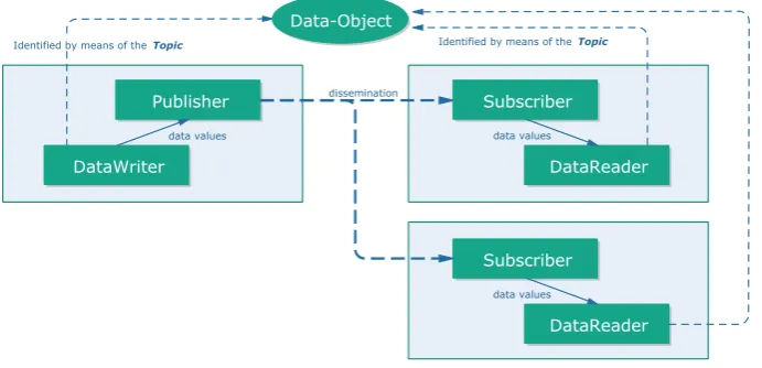
DDS is a high-performance middleware standardised by the Object Management Group (OMG). The DDS describes a Data-Centric Publish-Subscribe (DCPS) model for communic-ations between distributed appliccommunic-ations. The purpose of the DDS is to enable the “Efficient and Robust Delivery of the Right Information to the Right Place at the Right Time.” (Object Management Group, Inc., 2017) DCPS builds on a global data space, which is accessible to all interested applications. In the global data space, following communication objects are
intro-duced to aid the flowing of data:PublisherandDataWriteron the sending side;Subscriberand
DataReaderon the receiving side.
• APublisheris an object for data distribution. Data published by one publisher can be various types. Applications access to a publisher via aDataWriter. Applications must use the DataWriter to communicate to a publisher. The DataWriter is the object to handle the value of data-objects of a given type. APublicationis defined as the association of a DataWriter to a publisher.
• ASubscriberis an object used to receive data from the publisher and present the data to the receiving application. Same as the publisher, the subscriber may receive and
dis-patch different types of data. ADataReaderis an object attached to the subscriber and
accesses the data from the subscriber. Thus, aSubscriptionis defined by the association of a DataReader with a subscriber.
• ATopicis an object that provides an identifier that uniquely identifies some data items within the global data space. All subscribers connect to the interested publishers via topic.
The conceptual overview of DCPS model is shown in Figure 2.1
Identified by means of the Topic Identified by means of the Topic
DataWriter
Publisher Subscriber
DataReader
Subscriber
DataReader Data-Object
dissemination
data values data values
[image:7.595.131.477.487.654.2]data values
Figure 2.1:Conceptual overview of DCPS model (Object Management Group, Inc., 2017)
2.2 Android Development
2.2.1 Platform Architecture
Android is a software stack built for various types of mobile devices. The Android includes an operating system, middleware and key applications. The purpose of Android is to create an open source software platform for mobile network operators, original equipment manu-facturers (OEMs) and developers to realise innovative ideas and building real products. These products can effectively improve the mobile experience for users.
The Android stack consists five levels as shown in Figure 2.2, the Linux kernel, Hardware Ab-straction Layer (HAL), Android Runtime, Native C/C++ Libraries, Java Application Program-ming Interface (API) Framework, and System Applications. The three elements that are used in this assignment are the Linux kernel, the Native library, and the Java API Framework
• The Linux kernel. The Linux kernel is the foundation of the Android platform. The An-droid Runtime, which runs multiple Java virtual machines, relies on the Linux kernel for the functionalities, e.g. threading and low-level memory management. Additionally, the Linux kernel provides some of the Inter-Process Communication (IPC) mechanisms, e.g. signals, network sockets, and Unix domain sockets. We introduce the usage of the IPCs in Chapter 4.
• Native C/C++ Libraries. Many core Android system components and services are built from native code that requires native libraries written in C and C++. In this assignment, we build OpenDDS library based on these native libraries. In the following chapter, this layer is referred to as the native layer.
• Java API Framework. The most featured Android APIs are written in the Java language. In the following chapter, we refer this layer to as the Java layer. These APIs form the building blocks which can be used to create Android applications. The usage of these APIs simpli-fies the reuse of core, modular system components and services. These components and services include:
– View Systemto build an application’s Graphical User Interface (GUI),
– Resource Managerto provide access to localised strings, graphics, and layout files,
– Activity Managerto manage the life cycle of applications and provide a navigation stack for switching between different screens.
– Notification ManagerandContent Providersare unused in this assignment. There-fore, they are not introduced here.
2.2.2 Development Kits
For the development based on the native layer and Java layer, Google offers different develop-ment kits, Native Developdevelop-ment Kit (NDK) and Android Software Developdevelop-ment Kit (SDK). NDK enables to use native C/C++ code in applications, while SDK enables developers to write code in Java.
Despite Java is mostly used in Android development since the code related to user interface is required to be written in Java, and most functionalities provided by Android are presented in Java APIs, native C/C++ code is necessary under situations where:
• the code may be compute-intensive and have requirements of efficiency,
• the C/C++ code may already exist,
CHAPTER 2. BACKGROUND 5
Figure 2.2:Android stack (Google Inc., 2017a)
In this assignment, the DDS implementation we used is written in C++, and considering port-ability to other platforms, we utilize both SDK and NDK in the design.
2.3 Current Platforms in RoVe
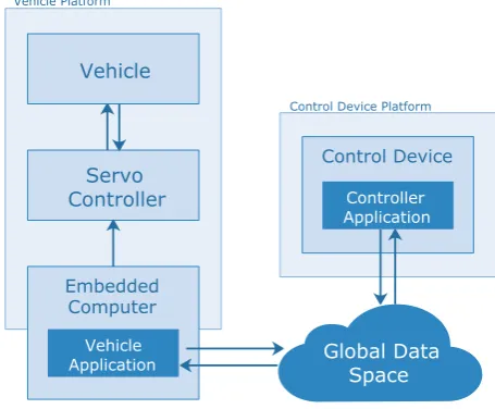
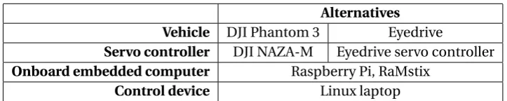
Currently, different platforms are presented in the project RoVe. The differences are in types of vehicles, onboard embedded computers, and control devices. Figure 2.3 shows an overview of the platforms. The arrows indicate data exchange. In this assignment, the embedded com-puter in the vehicle only sends set points to the servo controller. Therefore, the arrow between embedded computer and the servo controller is unidirectional, while all the other arrows are bidirectional. Additionally, Table 2.1 shows the alternatives in different platforms.
Embedded Computer
Servo Controller
Control Device Vehicle
Controller Application
Vehicle Application
Vehicle Platform
Control Device Platform
[image:9.595.186.414.551.739.2]Table 2.1:Alternatives in platforms
Alternatives Vehicle DJI Phantom 3 Eyedrive
Servo controller DJI NAZA-M Eyedrive servo controller
Onboard embedded computer Raspberry Pi, RaMstix
7
3 Analysis
3.1 Common Unmanned Vehicles
Nowadays, unmanned vehicles play increasingly important roles in modern society. In the field of law enforcement, they are also increasingly used for surveillance, search, and rescue, even riot control and chemical, biological agent detection. The deployment of the unmanned ro-botic systems in these tasks results in lower cost per flight hour than a manned helicopter, and lower risk of human life in dangerous operations.
In general, the unmanned vehicles have three different modalities based on where they operate (Murphy, 2014). If they operate
• on the ground, they are called Unmanned Ground Vehicles (UGVs);
• on the water, they fall into the general category of Unmanned Surface Vehicles (USVs);
• in the air, they may be called by various names including Unmanned Aerial Vehicles (UAVs), Unmanned Aerial Systems (UASs).
We focus on these remotely operated vehicles. The remotely operated vehicles are the vehicles which are controlled by an operator who is not in the vehicle. These vehicles can be oper-ated by radio control, or through a cable or line connecting the vehicle to the operator’s loca-tion. Besides, we only focus on the situation where the operators direct the vehicles via hand-controllers, e.g. 3-axis joysticks for vehicle rates. Autonomy is out of the scope of this assign-ment.
In this assignment, there are several roles in a remotely operated system. We define them here, and they will be commonly used in the rest part of this report.
• Operatoris a person who monitors the operated machine and makes the needed control actions.
• Controlleris an electronic hardware device that is used for receiving data from operators and sending to vehicles, also displaying information from the network. For example, a controller can be a laptop, a tablet, or a mobile phone. We will also call it control devices in following texts. Notice that the controller is not the servo controller in control engin-eering, and in this report, the controller is only referred to as the control device.
• Servo controlleris an loop controller that is responsible for the hard-time control of ser-vos in the vehicle.
• Input deviceis a device that generates movement commands from the operators’ inputs. For example, an input device can be a joystick or a keyboard.
• Vehicleis a mobile robotic system that receives the commands from the terminals and executes these commands to perform corresponding motions.
3.2 Current Work in Project RoVe
3.2.1 Data Distribution Service
There are growing types and numbers of unmanned vehicles being used by the police, as pre-viously mentioned. This brings concerns in the data communication. The difficulties can be broken down into following listed aspects (Pardo-Castellote, 2010).
• In vehicle platforms, the difficulty is that these platforms are mostly embedded and hence the power and memory resources are constrained.
• In data-link communications, the difficulty is that there might be many types of traffic, e.g. sensor data, command and control data, and status, mission, supervisory data. Also, the urgency, priority, reliability and volume for these different types of data vary from each other. Moreover, there are challenges in the communication channels, such as the channels with significant latency or low throughput.
• In controllers, the difficulties mainly fall in heterogeneous systems, multiple program-ming languages and requirements of reconfiguration.
These difficulties result in that it is time-consuming, error-prone, and inefficient to create an own data-link protocol. The introduction of middleware is aiming to tackle these problems. Middleware is computer software that provides services to software applications beyond those available from the operating system. It can be described as “software glue”. There are two main reasons for using middleware (Mohamed et al., 2008):
• achieving reusability of logic through a standardised, modular programming model,
• application developers being able to get rid of the underlying data distribution.
Currently, the Robot Operation System (ROS) is one of the most mainstream open-source robot middlewares in the field of robots. Compared to ROS, DDS has following advantages.
• The introduction of distributed network architecture in DDS eliminates the needs of central servers. A crash of single application will not influence the communication of other applications in the network. Thus, a single-point failure will not happen in DDS.
• DDS uses Quality of Service to configure the performance of the communication. This makes the communication more flexible.
• DDS is based on UDP/IP protocol. Multicast transmission greatly increases the network throughput and the real-time performance of the communication.
In the project RoVe, considering the advantages listed above, along with security, manageabil-ity, and interoperability issues, DDS was chosen to be the middleware in the whole architecture. Therefore, designing and implementing software based on the DDS is one of the requirements of this assignment.
3.2.2 Tasks in This Assignment
The increasing number of robotic systems brings two problems: how to control vehicles safely, and how to efficiently control the movements of vehicles.
For the first problem, redundancy is one of the approaches that increase the reliability of vehicle control. In engineering, redundancy is the duplication of critical components or func-tions of a system with the intention of increasing reliability of the system. In RoVe project, the feature of multiple operators makes it possible to introduce redundancy in the network.
CHAPTER 3. ANALYSIS 9
Redundancy is formed by control devices that multiple human operators held. When one con-trol device fails to send commands due to unstable network, program errors, or the battery run-ning down, one of the other control devices will step in and take over the control of the vehicle. The embedded computer in vehicles can also be a control device to control the vehicles when there is no other control device in the network, or when the vehicles drop out of the network. These behaviours ensure that the vehicles are always under control. Designing and implement-ing this redundant operator hierarchy is one of the issues need to be solved in this assignment.
On the other hand, the fixed operator hierarchy is sometimes not enough for performing a task. A handover scheme is needed in the hierarchy. Consider a situation where multiple op-erators are performing a task on a single robotic system, and the task requires collaborations between different operators. The control might need to be handed to another operator some-times. However, the handover is only performed when control devices join or quit the network. Therefore, to hand over control to a specific device without quitting the network, a handover scheme is needed.
For the second problem, the types of the vehicles are also increasing in the RoVe project. To make the data distribution scalable in the future, we need to design a stable control data model. The control data model represents movement commands from the operators. The design should take the universality and stability into accounts, which means the control data model should represent the movement commands for different types of vehicle with an identical in-terface.
3.3 Requirements
Based on the analysis and discussion above, we derive requirements for this assignment. The requirements are divided into several parts: the operator control hierarchy, the control com-mand module, the implementation and tests, and the general requirements.
3.3.1 Operator Control Hierarchy
Requirement 1:The hierarchy must exploit DDS standard as much as possible.
The design should rely on DDS standards. The DDS standards provide abundant QoS that can be used. Using these standards and QoS can minimise the occurrence of errors in the program and decrease the development time.
Requirement 2:The hierarchy must include a handover scheme.
As it mentioned in the last section, it is not possible to rely only on DDS standards in some circumstances. The preemption of control for operators is necessary. A handover scheme must be designed to handle the preemption.
3.3.2 Control and Command Module
Requirement 3: The control and command module should contain a control data model that can be used to control different types of vehicles with identical data structure.
Requirement 4:The control and command module could contain an input adapter that takes inputs from different devices and converts the inputs into the form of control data model.
Requirement 5:The control and command module should contain an output adapter that con-verts the movement commands in the form of control data model to the outputs that can be recognised by the servo controller.
Different user input devices, e.g. joysticks, keyboards, or virtual joysticks could be taken into consideration. The input adapter is capable of reading from these input devices and converting these inputs into the form of the control data model, while the output adapter is capable of converting the control data model to the servo control signals.
3.3.3 Implementation
Requirement 6:The implementation must be built based on OpenDDS.
The OpenDDS is an open source DDS implementation. Compared to other commercial imple-mentation of DDS standards, the open-source feature of OpenDDS ensures that we can com-pile the OpenDDS library freely and deploy our applications on different platforms without customization from providers. Thus, it brings more flexibility to the development. In project RoVe, OpenDDS has been chosen as the DDS implementation, therefore, using OpenDDS is a requirement of this assignment.
Requirement 7:The implementation must run on a Linux machine.
Requirement 8:The implementation should run on an Android device.
Currently, there is no document on how to develop the OpenDDS applications on Android devices. This adds uncertainties to the assignment. However, the implementation will be run-ning on a Linux machine at least.
Requirement 9: The implementation must have a graphical user interface for demonstrating the use of hierarchy and testing.
A graphical user interface must be presented to demonstrate the main functions of the hier-archy.
3.3.4 Tests
Requirement 10:Tests must be performed to evaluate the correctness of the hierarchy.
The correctness of the hierarchy is the first thing needs to be tested. These tests are aimed to ensure the handover process will eventually be done in good network conditions.
Requirement 11:Tests should be performed to evaluate the robustness of the hierarchy.
Fault-tolerance is one of the responsibilities of the hierarchy, so robustness is critical and needs to be checked. For example, the handover process should occur when a program crashes, or network fails.
Requirement 12:Tests could be performed to evaluate the correctness of the control data model.
This includes the test for different input devices, also the test for different types of vehicles.
Requirement 13: Tests should be able to perform without being connected to real vehicle plat-forms.
CHAPTER 3. ANALYSIS 11
Requirement 14:Tests won’t be carried out on platforms that currently not presented in the RoVe project.
The interfaces for other platforms will be taken into account in the design, but they will not be implemented or tested.
3.3.5 General Requirements
Requirement 15:Reusability, scalability, and extensibility must be considered in hierarchy and software design.
Object-oriented and certain design patterns should be introduced during design and coding to make the software open for extension.
Requirement 16:The software must be light-weight.
4 Design and Implementation
4.1 Operator Control Hierarchy
The design of the operator control hierarchy is broken down into two parts, static structure, and dynamic behaviour. In the static structure design, we first categorise types of operators and control devices and put them on different levels. Then, in each level, operators are fur-ther categorised by the controller devices they use. For the dynamic behaviour, we design the hierarchy based on the DDS standard and give explanations about the handover procedure in different situations.
4.1.1 Static Structure
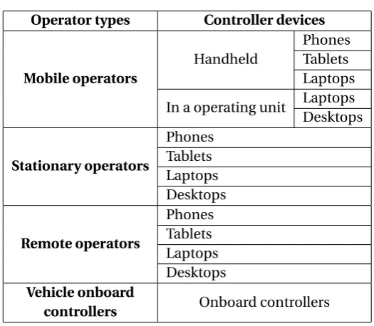
Operators are categorised by to what extent are the operators interested in controlling and getting information from the target unmanned vehicles. The operators are divided into three types.
The first operator type is the mobile operator. The mobile operators have the most interest in controlling the vehicles. These operators can be individual operators or operators in mobile operating units, e.g. operating vans. They manipulate the vehicles per instant visual feedbacks. They are the operators with most sufficient control information and feedbacks. These operat-ors can operate the vehicles more safely. Therefore, they have the highest priority when other types of operators are presenting in the network.
The second operator type is the stationary operator. The stationary operators are the operators in local control stations. They are not required to be in the visual range to the target vehicle. If they are in the visual range, the vehicles are controlled directly by visual feedbacks, as the mobile operators. When locations of local control stations are without the visual range, the operators will control the vehicles via feedbacks from onboard cameras or other sensors. This makes stationary operators less informative than the mobile operator. These operators are less interested in control of vehicles. Thus, the priority is less than mobile operators.
The third operator type is the remote operator. The remote operators are the operators without visual range. They can be in a control centre in e.g. another city. They are less interested in directly controlling the vehicle than the stationary operator. Therefore, the priority of the remote operator is the lowest among human operators.
The vehicle onboard controller is considered as the safety controller in the bottom of the hier-archy. The onboard controller seizes the control of the vehicles when no other active control device. This controller ensures that vehicles are always under control. When there are no other control devices in the network, this controller simply hovers the vehicles or runs an autonomy algorithm that directs the movement of the vehicles. This controller has the least priority and acts as the last protection of the vehicles.
Operators with same priority but different control device also need to be considered. Control devices also need to be categorised. We design that control devices with higher portability have higher priority since operators with more portable control devices can move easily to get better feedbacks from the vehicles. We list some types of the control devices here, such as mobile phones, tablets, laptops, and desktops.
Table 4.1 shows the design of the static structure.
4.1.2 Dynamic Behaviour
First, the hierarchy has close connections to theOWNERSHIPQoS in DDS. The exclusive mode
CHAPTER 4. DESIGN AND IMPLEMENTATION 13
Table 4.1:The Static Hierarchy
Operator types Controller devices
[image:17.595.170.433.94.323.2]Mobile operators
Handheld
Phones Tablets Laptops
In a operating unit Laptops
Desktops
Stationary operators
Phones Tablets Laptops Desktops
Remote operators
Phones Tablets Laptops Desktops
Vehicle onboard
controllers Onboard controllers
OWNERSHIP_STRENGTHcould write to the topic. In other words, these features make sure
that only the control device with the highest priority can write control commands to the vehicle. The mutually exclusive control of one vehicle relies on these features.
Before we discuss the hierarchy further, there are two concepts, priority and handover se-quence. The priority is related to preemption. The control devices with higher priority can seize the control from other control devices with lower priority. While the handover sequence is related to the action when one controller quits the hierarchy. Therefore, we use priority for handling the controller join and handover sequence for controller quitting.
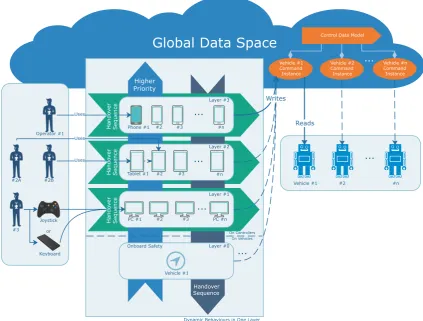
We can divide the hierarchy into two dimensions, as it is shown in Figure 4.1. We assume all the devices on each layer are intended to control Vehicle #1.
Vertically, there are different layers. In the bottom of the hierarchy, it is the onboard controller. As it mentioned in the last subsection, this layer is designed to handle the situation where no controller in the network is controlling the vehicle. Different from other layers, this layer is in the vehicle rather than the control devices, and we consider this layer is the last protection to prevent the vehicle from being uncontrolled. The other layers in the hierarchy are built in con-trol devices. The higher layers have more priority than the lower layers. When concon-trol device with higher priority joins, it seizes control from the lower layer devices automatically.
Horizontally, in each layer, there is only one type of control devices. For example, in Layer #2, they are all tablets. On the same layer, all the devices have the same priority. When one of these control devices quitting the network, the control will be handed to another control device in the same level automatically.
Consider one situation, in the network, Operator #1, #2A, and #2B are using different control devices. All of them are trying to control Vehicle #1.
In this situation, Phone #1 in the Layer #3 has the highest priority in the hierarchy. Thus, Phone #1 seizes the control of the vehicle from Tablet #1.
...
Handover Sequence
Higher Priority
PC #1 #2 #3 PC #n
[image:18.595.71.495.84.405.2]...
Tablet #1 #2 #n
... #3 #2 #n ... #3 Onboard Safety Phone #1
Global Data Space
Vehicle #1 Command Instance Vehicle #2 Command Instance Vehicle #n Command Instance ... Layer #0 Layer #1 Layer #2 Layer #3 ...Dynamic Behaviours in One Layer
Vehicle #1 #2 #n
Uses Uses Uses Hando ver Sequence Writes Vehicle #1 #2A #2B Operator #1 On Vehicles
Control Data Model
Joystick or Keyboard On Controllers Reads Hando ver Sequence Hando ver Sequence #3
Figure 4.1:Dynamic behaviours in each layer
When no device tries to write the command topic in the network, the onboard controller seizes the control automatically.
4.2 Control and Command Module
4.2.1 General Design
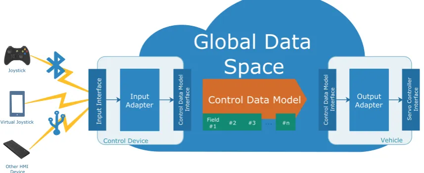
As it stated in subsection 3.3.2, the control and command module consists of the control data model and the adapters. An overview of control and command module is shown in Figure 4.2.
The control data model is defined as a data structure used to control the vehicle movements. Vehicles application reads and decodes control data model and converts to signals to be sent to the servo controller. Different types of vehicles share an identical control data model.
For the user input messages, various devices are used to generate such messages, such as joy-sticks or keyboards. To handle these different devices, we need certain interfaces and adapters to isolate changes.
CHAPTER 4. DESIGN AND IMPLEMENTATION 15
Vehicle Control Device
Control Data Model
Interface
Output Adapter Input
Adapter
Servo Controller
Interface
Input Interface
Other HMI Device Joystick
Virtual Joystick
Global Data
Space
Control Data Model
... Field
#1 #2 #3 #n
Control Data Model
[image:19.595.89.518.88.263.2]Interface
Figure 4.2:Overview of control and command module
4.2.2 Control Data Model Design
The common vehicles have been listed in section 3.1 and they are UAVs, UGVs and USVs. To design a control data model, we need to take these vehicles into considerations at least. As the control data model is used to control the movements of the vehicles, we focus on the movement command design in this subsection.
UAVs move in three-dimensional space, while UGVs and USVs move in two-dimensional space. We cannot control the position of UGVs and USVs in the z-axis. To design a control data model that fits both UAVs, UGVs and USVs, we can first design for UAVs and then modify it to make it suitable for UGVs and USVs, since UGVs and USVs are moving in a two-dimensional space, and we can easily reuse UAVs movement commands and ignore the control commands on the z-axis.
The movement commands are sent to the servo controllers in the vehicles. Since control data model is used on the top of the servo controllers, we use the interfaces of the servo controllers as the start point of control data model design.
4.2.3 Movement commands for UAVs
Currently, multi-rotors are mostly used in the drone world. Two UAVs that used in the project RoVe now are multi-rotors. However, there are also other types of UAVs. The typical types or designs of UAVs include fixed-wing, multi-rotor VTOL (Vertical Take-Off and Landing), nano, hybrids and others. In 2015, multi-rotor drone types accounted for a market share of more than 75 percent in the global commercial drone market. Besides, fixed-wing drones are the other major drone type (GPS World, 2016). Based on these data, we assume the mainstream types of UAVs are multi-rotor and fixed-wing. So, in the design, we consider these two kinds of UAVs.
DJI Naza-M multirotor autopilot Naza-M is the autopilot that currently used on the DJI Phantom 3 drone in the project RoVe. The movement control inputs of Naza-M are listed below.
• Roll
• Pitch
• Rudder (yaw)
• Throttle
• Additional control for mode switching, gimbal control, and others are the platform-specific functions
ArduPilot ArduPilot is used for multi-rotor and fixed-wing drones, and it also supports ground vehicles and boats. ArduPilot receives movement commands from radio control (RC) receiver. We derive the control interface of vehicles by listing the RC inputs. The RC inputs used in ArduPilot (ArduPilot Dev Team, 2016b) are listed below.
• Roll
• Pitch
• Throttle
• Yaw
• Flight modes
• (Optional) Inflight tuning or camera mount
Similar as Naza-M, the movement commands are throttle, pitch, and yaw. Besides movement commands, there are also mode switch, camera mount control, and platform-specific com-mands.
PX4 The RC inputs used in PX4 (Meier et al., 2017) are listed below.
• Throttle
• Yaw (Rudder)
• Roll (Ailerons)
• Pitch (Elevator)
• Mode switch (Manual/Auto)
• Function switch (Activation/Deactivation of individual stabilization functions)
Although at least six channels are needed, the movement control only relies on throttle, yaw, roll, and pitch. The rest channels are similar to Naza-M and ArduPilot. There have no camera control commands on PX4 autopilot.
CHAPTER 4. DESIGN AND IMPLEMENTATION 17
Therefore, we use quadruple formed by the throttle, pitch, roll, and yaw as movement com-mand interface for UAVs.
Besides, there are also additional commands in various autopilots. These additional com-mands can be divided into two types, the mode switch comcom-mands and the camera manipu-lation commands. We also take these two types of additional commands into considerations in the following design.
4.2.4 Movement Commands for UGVs and USVs
As it stated above, when the control command interface for controlling UAVs is chosen, the movement command of UGVs and USVs can be easily derived, since UGVs and USVs move in two-dimensional space. In this part, we will consider UGVs first, since UGVs have already presented in RoVe, and UGVs and USVs are very similar when it comes to control. In this sub-section, we analyse the current platforms in the RoVe project. Then, both the ArduPilot and PX4 autopilots support for rovers, so that we review these two autopilots as well.
Eyedrive Steering, throttle
ArduPilot Steering (roll), throttle, and flight modes
PX4 Steering (roll), throttle
From the examples listed above, for UGVs and USVs, the control signals are throttle and steer-ing values. However, there are differences in how to map steersteer-ing values into the aforemen-tioned quadruples formed by the throttle, pitch, roll, and yaw.
Intuitively, the steering values should be mapped into yaw, since the turning of vehicles is ro-tating around the z-axis. The reason ArduPilot and PX map steering to roll channel might be that, in standard RC transmitter, the throttle and yaw are on the same stick. If the steering maps to yaw, the throttle and steering will be manipulated by only one hand. This is hard to operate. Therefore, the steering is assigned to roll, as we can control the throttle and steering separately by two hands.
Compared to the pitch, the roll is more intuitive since the steering will direct the vehicles into left or right, in standard RC transmitter, the roll is changing in horizontal direction, while the pitch is in the vertical direction. Therefore, the steering is mapped to roll rather than pitch.
Under considerations above, we use quadruples formed by the throttle, pitch, roll to control the UGVs and USVs. However, the pitch and yaw are ignored in the UGVs and USVs control.
4.2.5 Additional Commands
As it mentioned in section 4.2.3, except the movement commands, there are also additional commands we need to consider. These additional commands can be categorised into camera manipulation commands and mode switch commands.
Despite the RoVe project mainly focuses on the surveillance and observation in law enforce-ment agencies, camera control commands are not be included in the control data model, be-cause the model is only responsible for the vehicle mobility. It is more reasonable to create another data model for the payload manipulation.
The other type of additional commands is the mode switch commands. Different autopilot providers define these commands. Therefore, these mode switch commands vary from each autopilot from different providers.
Naza-For different autopilots, there are sorted modes. However, these finely sorted modes should be adopted to specific models of autopilots when introducing new vehicles. It is developers’ responsibilities to perform the formatting and parsing of the enumeration for the specific plat-forms.
4.2.6 Control Data Model
According to the discussion above, a control data model is designed as below.
enum Command_type_t {
PROBE, MOVEMENT, MODE } ;
enum Mode_t {
MANUAL = 0 , ASSISTED = 10 , AUTO = 20 }
s t r u c t MovementCommand {
short t h r o t t l e ;
short r o l l ;
short pitch ;
short yaw ; } ;
s t r u c t ControlCommand {
long long s r c _ i d ;
long long dest_id ;
Command_type_t command_type ; MovementCommand movement_command ; Mode_t mode;
TimeBase : : TimeT timestamp ; } ;
Notice that the throttle, roll, pitch, and yaw are signed short type. Therefore, the value of these numbers ranges from -32767 to +32768. In this control data model, there is also some informa-tion that related to other topics, such as source ID, destinainforma-tion ID, and timestamp. These parts will be explained in following topic design section.
4.3 Topics
In the DDS, topics are the fundamental means of interaction between the applications in the network. The goal of the topic design is to meet the requirements of the system. Therefore, we use the requirements along with the functions that we need to realise as the entry point of the topic design.
According to the analysis and requirements in Chapter 3, the main functions can be categorised into following types:
• displaying devices that currently in the network,
CHAPTER 4. DESIGN AND IMPLEMENTATION 19
• sending or handling control commands.
According to these functions, we designed three topics to handle these businesses. These three topics are listed below.
• DeviceInfotopic. Used to maintain a list of the current online devices and inform the
changes in the ownership relations.
• RequestControl topic. Used to pass the requesting and replying messages for the
control rights.
• ControlCommandtopic. Used to deliver the commands to the vehicles.
In the following subsections, the detailed design of each topic will be given.
4.3.1 Important Concepts
Before we elaborate the design of the topics, several important concepts need to be clarified. These concepts include keyed topic, content-filter topic and some QoS policies used in the topic design.
Keyed topic Each topic data type can specify zero or more fields that make up itskey. In DCPS terminology one can publish individual data samples for different instances on a topic (Object Computing, Inc., 2017b). Each instance is associated with a unique value for the key. If a topic is keyed, the instances can be independently maintained, and the key forms the unique identifiers of data objects.
Content-filtered topic A content-filtered topic is a topic with filtering properties. The usage of content-filtered topic enables us to only get the data that we are interested in from the topic.
For example, consider we have a topic that contains control commands, but vehicles are only interested in the control commands whose destination is the vehicles. The content-filtered topic can filter out all the samples that are not sent to the target vehicle.
Important QoS policies Following QoS policies are used in this assignment.
• Durability. TheDurabilitypolicy specifies whether data writers should keep samples after the samples have been sent to known subscribers. That is, whether the late-joining data readers can receive the previous samples published in the data writer.
• Liveliness. TheLivelinesspolicy controls when and how DDS services determine the
availability of participants changes. If we set theLivelinesstoAUTOMATIC, the DDS
service will send a liveliness notification if the participant has not sent any network traffic
in lastlease_duration.
• Ownership and Ownership_strength. The Ownership policy specifies whether
mul-tiple data writers can write samples of the same instance. If Ownership is set to
EXCLUSIVE, only one data writer is allowed to write to the same instance. The data
writer is elected by value of theOwnership_strengthpolicy. The data writer with
highestOwnership_strengthowns the instance.
4.3.2 DeviceInfo Topic
the vehicle asking for control. This operation cannot be done without knowing the identifica-tion of the vehicle. Therefore, a unique identificaidentifica-tion for both controllers and vehicles in the network is needed.
It is also required to know which controller is currently controlling a specified vehicle. An
op-erator with high priority can control several vehicles at the same time. TheOwnershipQoS
policy of DDS guarantees this behaviour. However, DDS does not explicitly provide APIs to check which data writer is the owner of a sample in topics. This is an important reason to
cre-ate aDeviceInfotopic to store the information of ownership relations, i.e. which controller
currently controls this vehicle. The detailed way of how to realise this function will be given in
following section 4.3.6 since this function needs collaborations withControlCommandtopic.
To conclude, the reasons for building this DeviceInfo topic is, first, one device needs a
unique identification in the network. Second, the operators need to recognise the ownership relations between the vehicles and controllers explicitly.
To satisfy the functions mentioned above, we design theDeviceInfotopic as follow.
enum Device_type_t {
VEHICLE , CONTROLLER } ;
s t r u c t DeviceInfo {
long long device_id ; s t r i n g name ;
Device_type_t device_type ;
long long c o n t r o l l e r _ i d ; } ;
Notice that thecontroller_idfield is only applicable to vehicles, and it indicates which
controller is currently controlling the vehicle. For controllers, this field is left unused in the program.
Each device should maintain one sample in this topic. Therefore, the key of this topic is the device ID. Besides, the QoS settings need to be configured in this topic.
DurabilityQoS policy The default kind of this QoS isVOLATILE_DURABILITY_QOS. Under this default QoS, DDS does not store the samples after they are delivered. Therefore, late-joining data readers will not get any information from the data writer that already online. However, the late-joining data readers should also get the information from all the currently
online devices to generate an online device list. Thus, theDurabilityQoS needs to be set
toTRANSIENT_LOCAL_DURABILITY_QOS. Under this QoS, the DDS will attempt to keep
samples so that they can be delivered to any potential late-joining data readers.
LivelinessQoS policy The default kind of this QoS isDDS_AUTOMATIC_LIVELINESS_QOS, which means DDS will automatically assert liveliness for the DataWriter at least as often as the
lease_duration. However, the defaultlease_durationof this QoS is infinite, which
means DDS will not check the liveness of the data writers. This causes problems when a DDS program quits abnormally, or network blocked. The DDS does not assert the liveliness of these data writers and the DDS will assume the data writers in this program still alive. The
lease_durationofLivelinessQoS policy need to be set to a certain value rather than
CHAPTER 4. DESIGN AND IMPLEMENTATION 21
exact value oflease_duration, it depends on the users’ specific requirements. We set
lease_durationto one second here.
4.3.3 RequestControl Topic
This topic is to pass the messages for requesting for control. In a requesting and answering handover process, there are three roles as it listed below.
• Requester. The controller asks for the control of a vehicle.
• Replier. The controller currently controls the vehicle.
• Vehicle.
The designed process of the active handover is shown as followed.
1. The requester sends a request. The request includes the ID of the vehicle that the re-quester intends to control, the ID of the replier, and the ID of the rere-quester. The replier is the current controller of the vehicle. The ID of the replier can be derived by checking the local device list.
2. The replier receives the request, waiting for the operator accepting or declining the re-quest. If the operator declines, the handover will end.
3. If the operator accepts, the replier will publish an accept message in the network to in-form the requester to take actions.
4. The requester receives the response and takes steps to seize the control of the vehicle.
The detailed actions of the replier and requester take after operator accepting are given in the
following subsection 4.3.4, since it is related to theControlCommandtopic.
According to the discussions above, we give the static structure of this topic here.
enum ack_t {
REQUEST, ACCEPT, REFUSE, FINISH } ;
s t r u c t RequestControl {
long long s r c _ i d ;
long long dest_id ;
long long c u r r e n t _ c o n t r o l l e r _ i d ;
long s r c _ p r i o r i t y ; ack_t ack ;
TimeBase : : TimeT timestamp ; } ;
When a requester wants to send a request, the only information needs to be provided
by the user is the dest_id, i.e. the ID of the vehicle that requester intends to
con-trol. Since the program stores the current device information of all the devices online, the
current_controller_idof the vehicle can be derived from the device list. Finally, the
net-When a replier receives and accepts the request, the replier will modify theackfield of the
re-quest message toACCEPTand publish this response to the network. The requester will receive
this message and take actions.
However, not all devices need to receive this message. Only devices with ID equal to the
current_controller_id, orsrc_id(to receive responses) need to receive the messages
from this topic. Therefore, we need to set this topic to a content filtered topic to filter irrelevant messages.
Thesrc_priorityis a reserved field currently. This field is supposed to realise a priority
checking function in the future, i.e. if thesrc_priorityis lower than current controller’s
priority, the current controller will directly hand over the control to the requester without ask-ing the permission from the operators.
The QoS of this topic is set to default.
4.3.4 ControlCommand Topic
This topic is to deliver commands to vehicles. Moreover, it is the core part of handover. The interface description of this topic is intuitive. The description is shown in previous subsection
4.2.6. Except for the movement commands that control the vehicles, there are onlysrc_id
anddest_id. Thesrc_idis the controller ID, and thedest_idis the vehicle ID. The
con-trol commands are sent fromsrc_idtodest_id.
When multiple controllers write to one vehicle, the vehicle should not take all the messages, but only the messages from the owner of this sample. The owner is the data writer with the
highest priority. The DDS’sOwnershipQoS policy ensures this mutually exclusive behaviour.
Moreover,Ownershipapplies on a per key value basis for keyed topics. This means if a topic is keyed, every instance in the topic has an owner. Since one vehicle should only take commands from one controller, the key of the topic should be set to the vehicle’s ID, i.e. thedest_idfield of the interface description. So that for each vehicle, multiple controllers can write to it, but the vehicle only takes commands from the controller with the highest priority.
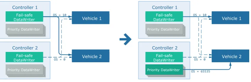
In this way, the DDS ensures the passive handover. However, the situation is different under the active handover. Consider a situation where there are two controllers and two vehicles in the network, as shown in Figure 4.3.
In this figure, assume the data writer in Controller 1 has higherOWNERSHIP_STRENGTHthan
data writer in Controller 2. After all the devices become online, Controller 1 will seize the
con-trol of Vehicle 1 and Vehicle 2, since Concon-troller 1 has the highestOWNERSHIP_STRENGTHin
the network.
The solid lines in the figure indicate that this data writer is the owner of the data reader in the vehicle. The dotted lines indicate that the data writer is not the owner of the data reader. For these dotted lines, although the writer can write to the reader, the reader will drop the sample sent by this data writer. When the other controllers quit the network, these controllers with dotted lines have the chances to be the new owner of the vehicle. They are the redundant controllers in the network.
Consider the situation where Controller 2 now wants to control Vehicle 2. Some steps should
be taken here to increase theOWNERSHIP_STRENGTHof the data writer in Controller 2. If
we directly increase theOWNERSHIP_STRENGTHof the data writer in Controller 2 and make
it larger than the data writer in Controller 1, the data writer in Controller 2 will also seize the
control of the Vehicle 1 since it has higherOWNERSHIP_STRENGTHnow. This is not ideal since
we only intended to seize the control of Vehicle 2.
CHAPTER 4. DESIGN AND IMPLEMENTATION 23
Controller 1
DataWriter Vehicle 1
Controller 2
DataWriter Vehicle 2
DataWriter
DataWriter
Vehicle 1
Vehicle 2 Controller 1
DataWriter Vehicle 1
Controller 2
DataWriter Vehicle 2
DataWriter
DataWriter
Vehicle 1
Vehicle 2 OS = 0
OS = 10 OS = 10
[image:27.595.93.515.77.200.2]OS = 20
Figure 4.3:Problem caused by two controllers with only one data writer in each
to different vehicles at the same time. The priority writers are only created when active
han-dover happens. The values ofOWNERSHIP_STRENGTHof all the priority writers are the same
and equal to a number larger than all the fail-safe writers’OWNERSHIP_STRENGTH. Besides,
different from fail-safe writer, one priority writer can only write to a single vehicle. If the oper-ator wants to seize control of several vehicles, multiple priority writers should be created. By introducing the priority writers, we do not need to change the value of any fail-safe writers, and the active handover will not influence other vehicles in the network.
[image:27.595.92.517.449.588.2]For example, still consider the situation above, but priority writers are added, as shown in Figure 4.4. When Controller 2 wants to seize the control of Vehicle 2, Controller 2 only needs to create a priority writer to Vehicle 2. Vehicle 2 will then automatically be owned by the priority writer. At the same time, Vehicle 1 is still being controlled by Controller 1, be-cause the priority writer of Controller 2 will not write to Vehicle 1 and the writer with highest
OWNERSHIP_STRENGTHamong all the data writers to Vehicle 1 is still the data writer in
Con-troller 1. Controller 1 Priority DataWriter Priority DataWriter Priority DataWriter DataWriterFail-safe
DataWriter Vehicle 1
Controller 2 Priority DataWriter Priority DataWriter Priority DataWriter Fail-safe DataWriter
Vehicle 1Vehicle 2 Controller 1
Priority DataWriter Priority DataWriter Priority DataWriter
DataWriterFail-safe
DataWriter Vehicle 1
Controller 2 Priority DataWriter Priority DataWriter Priority DataWriter Fail-safe DataWriter
Vehicle 1Vehicle 2 OS = 0
OS = 10 OS = 10
OS = 0
OS = 65535
Figure 4.4:Controllers with fail-safe writer and priority writer
When Controller 1 wants to get the control of Vehicle 2 back, and Vehicle 2 is currently con-trolled by Controller 2 with a priority writer. The operator of Controller 1 can send a request to Controller 2. If the operator of Controller 2 approves this request, Controller 2 will immediately delete the priority writer to Vehicle 2, while Controller 1 will create the priority writer to Vehicle
2 after Controller 1 receives the approval message from theRequestControltopic.
4.3.5 QoS Policy Summary
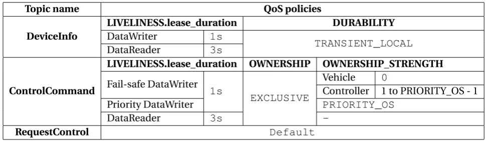
Based on the discussion above, we conclude the QoS for each topic as shown in following Table 4.2. The QoS policies that not listed in the table are all set to default values. These defalut values can be found in OpenDDS developer’s guide (Object Computing, Inc., 2017b).
Notice theOWNERSHIP_STRENGTHof the fail-safe DataWriter in the vehicle is set to 0, since it
is the safety layer in the operator control hierarchy. TheOWNERSHIP_STRENGTHon controller
is set according to the level in the operator control hierarchy. However, the largest value of
fail-safe DataWriter’sOWNERSHIP_STRENGTHshould not exceed theOWNERSHIP_STRENGTHof
[image:28.595.69.554.239.380.2]the priority DataWriter. ThePRIORITY_OScan be set to a number large enough, say 65535.
Table 4.2:QoS policy summary
Topic name QoS policies
DeviceInfo
LIVELINESS.lease_duration DURABILITY
DataWriter 1s
TRANSIENT_LOCAL
DataReader 3s
ControlCommand
LIVELINESS.lease_duration OWNERSHIP OWNERSHIP_STRENGTH
Fail-safe DataWriter 1s
EXCLUSIVE
Vehicle 0
Controller 1 to PRIORITY_OS - 1
Priority DataWriter PRIORITY_OS
DataReader 3s
-RequestControl Default
4.3.6 Listing Ownership Relations
As it mentioned in the design of theDeviceInfotopic, the function of listing the relations
of ownership between the controllers and vehicles needs to utiliseControlCommandtopics.
The handling of ownership is in the DDS implementation and the DDS does not provide the APIs for acquiring the ownership relations. We need to design a method to realise this function.
The designed method is that every time the control commands being written to the vehicle,
if thesrc_iddoes not equal to the vehicle’s current_controller_id, the vehicle
up-datescurrent_controller_idfield in its sample ofDeviceInfotopic. The value will
be changed to thesrc_idof the control command. Then theDeviceInfowriter will
pub-lish the sample in the network. All the devices in the network get this update on ownership relations. The reason for designing a method like this is that, if a data writer can write the con-trol command to a vehicle, this data writer must be the owner of the data reader in the vehicle. The DDS guarantees this behaviour. Notice the vehicle only publishes new sample when the
current_controller_idchanges, therefore, the method will not cause a large amount of
traffic during theControlCommandtopic being written by control devices.
As for the update timing, when there are new samples or liveliness changes in the
DeviceInfo topic, every controller in the network that receives these messages will
act-ively write commands to all the vehicles in the device list. The reason is that the new sample arriving and liveliness changing indicates that there are devices go online or offline, the ownership relations might be changed due to this. However, it is found in the preliminary experiments, and the source code of OpenDDS, the ownership information will not change until new samples write to the topic. Therefore, we need to probe the topic actively to acquire current ownership relations. Besides the new samples arriving and liveliness changing, the update will also happen after the active handover.
CHAPTER 4. DESIGN AND IMPLEMENTATION 25
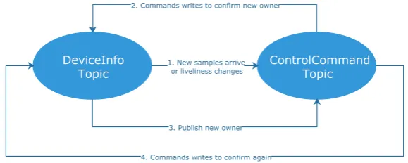
The procedure of deriving the ownership relations is shown in Figure 4.5. The arrows in the figure mean the events will cause reactions in destination topic somehow other than the events write to the topic directly.
DeviceInfo
Topic 1. New samples arriveor liveliness changes ControlCommandTopic
2. Commands writes to confirm new owner
3. Publish new owner
[image:29.595.156.446.127.243.2]4. Commands writes to confirm again
Figure 4.5:Procedure of updating relations
The trigger to update the relations is the new samples arriving or liveliness changing. The pro-gram on each controller will then write commands to all the vehicles in the device list. If the owner of the vehicle changes, the program in the vehicle will receive the control commands
from the owner. If thesrc_iddoes not equal to thecurrent_controller_id, the vehicle
will publish a new sample in theDeviceInfotopic. The arriving of this new sample causes
the fourth action in the figure to recheck the ownership. If there is no change in ownership relations, the update will end.
The updated ownership relations are in the current_controller_id field of each
vehicle’s DeviceInfo sample. Moreover, this sample has already published in the
net-work, and every device has a copy of this relation. So, the operators can explicitly know the ownership relations between all the devices in the network.
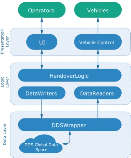
4.4 Software Architecture
Based on the requirements and the functions, the software consists of three parts: the handover logic, the GUI application, and the vehicle application.
The handover logic is designed to handle the passive and active handover processes as it stated in previous section 4.3, and interact with the messages from the DDS. This part is reusable, which means the codes of the handover logic on the GUI application and the vehicle applica-tion is identical.
The GUI application is used to interact with the operators, and the vehicle application is used to receive the commands from the operators. Also, there is a safety checking in the vehicle application to ensure the commands that vehicles receive are valid and up-to-date.
To organise the codes in a flexible and maintainable way, we apply three-tier architecture to the software design. A three-tier architecture is a client-server software architecture pattern in which the user interface (presentation), functional process logic (business rules), computer data storage and data access are developed and maintained as independent modules (Ecker-son, 1995).
In our case, the presentation layer refers to the GUI application for operators, also the vehicle application. We consider the DDS part as the data layer, which provides the functions of access-ing and modifyaccess-ing data in the global data space. The logic layer refers to the handover logic, which handles the data from the DDS and takes corresponding actions.
HandoverLogic
Logic Layer
Presentation
Layer
DDS Global Data Space
DataReaders
Data Layer
DataWriters
UI Vehicle Control
Operators Vehicles
[image:30.595.173.397.77.347.2]DDSWrapper
Figure 4.6:Overview of software architecture
4.4.1 Detailed Software Architecture Design
Android environment As it mentioned in section 3.3, the software should run on an Android tablet. This brings a problem, and that is, we cannot directly use OpenDDS APIs under Android environment.
The language widely used in Android application development is Java. According to the OpenDDS website (Object Computing, Inc., 2017c), OpenDDS is an open source C++ imple-mentation of the DDS, and it supports Java bindings through Java Native Interface (JNI) (Or-acle, 2017). However, the OpenDDS only supports for compiling under Android NDK (Ob-ject Computing, Inc., 2017a)but not Android SDK. The Java bindings are disabled under cross-compiling. This means we cannot use the Java bindings of OpenDDS under Android environ-ment.
In the implementation, we write codes related to the DDS in C++ and use NDK to make the logic library running on an Android tablet.
Communications between the logic and GUI As it mentioned above, because of the differ-ences in programming languages, we need to write the codes related to the DDS in C++ and the codes related to GUI in Java in the Android environment. This forces us to separate the GUI or vehicle application with the handover logic.
The separation increases reusability. When we want to build GUI or vehicle applications for an-other platform, we can leave the handover logic unchanged and only create the application for the specific platform. From the perspectives of the development time, this separation results in more time of development. However, this will give inspirations for designing and implement-ing the GUI applications with OpenDDS on different platforms.
JNI is the bridge between Java and C++. We can directly call the functions in the handover logic as shown in Figure 4.7
CHAPTER 4. DESIGN AND IMPLEMENTATION 27
Handover Logic Graphical User Interface
Application
Facade
Java
[image:31.595.189.415.80.195.2]C++ JNI
Figure 4.7:Interaction between C++ and Java codes via JNI
• It is hard to pass the parameters or results with the types other than the primitive types. JNI supports the arrays composed of single primitive type, such as integer ar-rays. However, we might need to transfer an array with customised data structures, e.g.
DeviceInfo. Each instance ofDeviceInfo contains three 64-bits integers and a
string. This array cannot be transferred directly through JNI. Therefore, we need transfer the parameters via pointers. However, this adds the memory management issues, and it is error-prone in implementations.
• JNI only works for Java. In other programming languages, bridges between the languages and the C++ are different.
Consider these two drawbacks brought by JNI, we give up using JNI for communication, and we design another method to realise the communication between the logic codes written in C++ and the languages used in GUI development.
The new method is shown in Figure 4.8. The GUI applications do not call the logic directly. Instead, the GUI applications wrap the functions and parameters in a message packet and send the packet through the communication links to the process of logic codes. The process of logic codes will receive these messages from the communication links. Then, the process will handle these messages and take corresponding actions. This method decouples logic codes and GUI and makes it easier for extending in future development.
Serialisation/Deserialisation
Handover Logic Graphical User Interface
Application
Facade C++
Serialisation/Deserialisation
Communication Link StreamBinary Java, .NET, or
Objective-C
Figure 4.8:A method to communicate between C++ and Java codes without JNI
[image:31.595.191.415.528.659.2]Serializ-Serialization is the process of translating data structures or object state into a format that can be stored or transmitted (for example, across a network connection link) and reconstructed later, possibly in a different computer environment. In our case, we refer the different computer environments to the different languages used in logic and GUI codes.
There are different types of serialisation methods. The serialisation and deserialization can be done manually. However, it is time-consuming to create this tailored solution since we need to write two sets of codes for both C++ language and the other language. Using third-party serialisation tools is an alternative. These tools are relatively mature. Some of the tools provide code-generation via interface description language files. This makes it easier to maintain and scale in future development.
The widespread serialization methods include Extensible Markup Language (XML), JavaScript Object Notation (JSON) and protocol buffers (Google Inc., 2017b), etc. The following texts will compare between these three methods.
• XML
The initial goal of XML is to mark the documents on the Internet. Therefore, making it readable for both human and machine is embedded in its design concepts. However, when using in the serialisation, XML becomes verbose and complex.
• JSON
Originated from the JavaScript, a weak type programming language, JSON uses the “Attribute-value” pair to describe the objects. JSON remains the human-readable fea-ture. At the same time, JSON drastically reduces the size after serialisation compared to XML.
The simplicity of JSON brings both advantages and disadvantages. During serialization and deserialization, there are no Interface description language (IDL) files used to con-strain the design. If in the future, the development separated into business logic and GUI application development and assign these different development tasks to different developers, lack of uniform interfaces will cause inconvenience to develop and debug.
• Protocol buffers
Protocol buffers are a language-neutral, platform-neutral extensible mechanism for seri-alizing structured data. Compared with XML, protocol buffers are simpler, 3 to 10 times smaller, are 20 to 100 times faster (Google Inc., 2017b). And protocol buffers use stand-ard IDL and provide compiler for code-generation, therefore, protocol buffers are less ambiguous compared to both XML and JSON. Compared to JSON, the standard IDL of protocol buffers also ensure the scalability for future development.
According to the discussions above, due to the considerations of reusability and scalability, we choose protocol buffers as the serialisation tool.
Communication links Since we give up the scheme of directly calling APIs from the handover logic, communication mechanisms should be introduced to make different languages commu-nicate with each other.
For the development upon the Android layer, Google provides Android-specific IPC mechan-isms, primarily including Intents, Binder, and Messenger (Shao et al., 2016). For the develop-ment upon native layer, as Android also relies upon a tailored Linux environdevelop-ment, it provides a subset of traditional Linux IPCs (which are distinct from Android IPCs), such as signals, net-work sockets, and Unix domain sockets.