Orcad
®
Component Information System
Cadence PCB Systems Division 13221 SW 68th Parkway, Suite 200 Portland, OR 97223
Trademarks
Allegro, Ambit, BuildGates, Cadence, Cadence logo, Concept, Diva, Dracula, Gate Ensemble, NC Verilog, OpenBook online documentation library, Orcad, Orcad Capture, PSpice, SourceLink online customer support, SPECCTRA, Spectre, Vampire, Verifault-XL, Verilog, Verilog-XL, and Virtuoso are registered trademarks of Cadence Design Systems, Inc.
Affirma, Assura, Cierto, Envisia, Mercury Plus, Quickturn, Radium, Silicon Ensemble, and SPECCTRAQuest are trademarks of Cadence Design Systems, Inc.
Alanza is a service mark of Cadence Design Systems, Inc.
All other brand and product names mentioned herein are used for identification purposes only and are registered trademarks, trademarks, or service marks of their respective holders.
60-30-616
Second edition 31 May 2000
Cadence PCB Systems Division (PSD) offices PSD main office (Portland) (503) 671-9500
PSD Irvine office (949) 788-6080
PSD Japan office 81-45-682-5770
PSD UK office 44-1256-381-400
PSD customer support (877) 237-4911
PSD web site www.orcad.com
Contents
Before you begin ix
Welcome . . . ix
How to use this guide . . . x
Symbols and conventions . . . x
Related documentation . . . xi
What is the Orcad Component Information System? 1
Chapter 1
Overview . . . 1CIS product history . . . 3
The internet component assistant (ICA) . . . 4
CIS in the PCB design process . . . 5
The CIS work environment . . . 6
The CIS explorer window . . . 6
The footprint window . . . 7
The part window . . . 8
The visibility window . . . 8
The explorer window . . . 8
The database parts window . . . 9
The ICA home page . . . 9
The part manager window . . . 10
Setting up Orcad CIS 11
Chapter 2
Overview . . . 11Creating a part database . . . 12
Choosing a database format . . . 12
Determining part properties . . . 14
Setting the field format . . . 20
Using more than one table . . . 20
Creating a part database from an existing design . . . 20
Extracting ERP or MRP database part information . . . 22
Creating a configuration file . . . 26
Using the database configuration wizard . . . 26
Creating a configuration file manually . . . 32
Editing a configuration file . . . 36
Setting database table property options . . . 36
Defining part reference associations . . . 43
Setting administrative preferences . . . 47
Setting ICA supplier preferences . . . 50
Saving the configuration file . . . 52
Setting up the ICA to access external part data . . . 53
Creating Crystal Reports templates . . . 54
Working with database parts 57
Chapter 3
Overview . . . 57Using the CIS interface . . . 58
Using the part manager window . . . 58
Using the CIS explorer window . . . 60
Using docking windows . . . 61
Using the database parts window . . . 63
Placing a database part on a schematic page . . . 66
Using the explorer to locate a database part . . . 66
Using the query feature to locate database parts . . . 67
Creating and executing a query . . . 67
Placing a local database part on your schematic . . . 69
Browsing part properties . . . 71
Creating a new database part . . . 72
Deriving a new database part from the local part database . . . 72
Deriving a new database part from a placed part . . . 77
Using the ICA to locate and create a new database part . . . 81
Using the ICA to locate a part . . . 81
Using the ICA to create and place a part . . . 82
Linking a placed part to a database part . . . 88
Viewing a placed part’s database properties . . . 92
To view a placed part’s database properties . . . 92
Copying part properties using the part manager . . . 94
Finalizing and documenting designs 97
Chapter 4
Overview . . . 97Viewing and updating part status . . . 98
Opening the part manager . . . 98
Contents
Saving the status report . . . 102
Creating design variants . . . 103
Creating reports . . . 104
Creating a standard CIS bill of materials . . . 104
Creating a report using a Crystal Reports template . . . 109
Glossary 115
Tables
Before you begin
Welcome
Orcad family products offer a total solution for your core design tasks: schematic- and VHDL-based design entry; FPGA and CPLD design synthesis; digital, analog, and mixed-signal simulation; and printed circuit board layout. What's more, Orcad family products are a suite of
applications built around an engineer's design flow—not just a collection of independently developed point tools. Orcad Component Information System (CIS) is just one element in our total solution design flow.
How to use this guide
This guide is designed so you can quickly find the information you need to use Orcad Component Information System (CIS). To help you learn and use Orcad CIS efficiently, this manual is separated into the following sections:
• What is the Orcad Component Information System? on page -1
• Setting up Orcad CIS on page -11
• Working with database parts on page -57
• Finalizing and documenting designs on page -97
Symbols and conventions
Our printed documentation uses a few special symbols and conventions.
Notation Examples Description
C+r Press C+r Means to hold down the C key while
pressing r. A, f, o From the File menu, choose Open (A, f,
o)
Means that you have two options. You can use the mouse to choose the Open command from the File menu, or you can press each of the keys in
parentheses in order: first A, then f, then o.
Monospace font In the Part Name text box, type PARAM. Text that you type is shown in monospace font. In the example, you type the characters P, A, R, A, and M.
UPPERCASE In Capture, open CLIPPERA.DSN. Path and filenames are shown in uppercase. In the example, you open the design file named CLIPPERA.DSN. Italics In Capture, save design_name.DSN. Information that you are to provide is
How to use this guide
Related documentation
In addition to this guide, you can find technical product information in the online help, the online interactive tutorial, online books, and our technical web site, as well as in other books. The table below describes the types of technical documentation provided with Orcad
Component Information System (CIS).
This documentation component . . . Provides this . . .
This guide—
Orcad Component Information Sytem User’s Guide
A comprehensive guide for understanding and using the features available in Orcad CIS.
Online help Comprehensive information for understanding and using the features available in Orcad CIS.
You can access help from the Help menu in Orcad CIS, by choosing the Help button in a dialog box, or by pressing 1. Topics include:
• Explanations and instructions for common tasks. • Descriptions of menu commands, dialog boxes, tools on
the toolbar and tool palettes, and the status bar. • Error messages and glossary terms.
• Reference information. • Product support information.
You can get context-sensitive help for a error message by placing your cursor in the error message line in the session log and pressing 1.
Online interactive tutorial A series of self-paced interactive lessons. You can practice what you’ve learned by going through the tutorial’s specially designed exercises that interact directly with Orcad CIS. You can start the tutorial by choosing Learning Orcad CIS from the Help menu.
Online Orcad Component Information Sytem User’s Guide
An online, searchable version of this guide, available when choosing Online Manuals from the Orcad family program group (on the Start menu).
Orcad family customer support at www.orcad.com/technical/technical.asp
An Internet-based support service available to customers with current support options. A few of the technical solutions within the customer support area are:
• The Knowledge Base, which is a searchable database containing thousands of articles on topics ranging from schematic design entry and VHDL-based PLD design to PCB layout methodologies. It also contains answers to frequently asked questions.
• The Knowledge Exchange, which enables you to share information and ideas with other users and with our technical experts in a real-time online forum. You can submit issues or questions for open discussion, search the Knowledge Exchange for information, or send email to another participant for one-on-one communication. A list of new postings will appear each time you visit the Knowledge Exchange, providing you with a quick update of what's been discussed since your last visit. • The Technical Library, which contains online customer
support information that you can search through by category or product. You can find product manuals, product literature, technical notes, articles, samples, books, and other technical information. Additionally, technical information can be obtained through SourceLink, which is an online customer support information service for users of Cadence software other than Capture, Component Information System (CIS), Express, Layout, or PSpice.
• The Support Connection, which allows you to choose to either view and update existing incidents, or create new incidents. The information is delivered directly to us via our internal database. This service is only available to customers with current maintenance or Extended Support Options (ESOs) in the United States and Canada.
• The Live Connection, which enables you to open access to your computer to a Customer Support person, who can then view your actions on your computer monitor as you demonstrate the problem you're having. Live Connection's two-way transmission can also let you view the actions on the Customer Support person's computer monitor, as he or she demonstrates a method or procedure to help you solve your problem. To participate in Live Connection, you need to contact a Customer Support person, in order to obtain a support number to grant you access to the Live Connection site, and to set up a time to “meet online” using Live Connection.
What is the Orcad Component
Information System?
1
Overview
Orcad Component Information System (CIS) is a part management system that is available as an option for use with Orcad Capture. Orcad CIS helps you manage part properties (including part information required at each step in the printed circuit board design process, from implementation through manufacturing) within your schematic designs.
CIS provides access to local (preferred parts database) and remote part databases that contain all relevant
information for the parts used in your designs. This information may include company part numbers, part descriptions, PCB layout footprints, technical parameters (such as speeds, tolerances, and ratings), and purchasing information.
when you place the part. CIS maintains a link to the engineering database part so that you can retrieve other part properties at any time. Linking placed parts to your preferred parts database gives you access to complete part information during the schematic design process.
If you need a part for your design that is not yet in the parts database, you can create the part in the design and add the part to your part database immediately or at a later time. You can also link a non-database part you’ve created before to a database part at any time.
Orcad Layout Libraries Orcad Capture Libraries Activeparts Database Orcad Layout Libraries Orcad Capture Libraries Supplier Pricing & URLs to
Local
Preferred
Part
Data
External
New
Part
Data
Preferred Parts Database ODBC Combined or separate databases Corporate Database (MRP/ERP/PDM) Orcad CaptureOrcad CIS
Upload BOM to corporate system ReportsTab delimited ASCII Comma delimited ASCII MS Access database format
CIS product history
CIS product history
Orcad CIS Release 9 is the latest version of the Orcad Enterprise CIS product offering. With the release of version 7.2 in April 1998, the Orcad Enterprise CIS family was the evolution and final merging of two popular Orcad CIS product lines—Enterprise Edition and EDA-Bridge. Enterprise Edition evolved from the DDL product originally developed by an Orcad Industry Partner called Q-Point. Q-Point was acquired by Orcad in June 1997. Orcad Enterprise Edition was packaged and shipped under the product names Orcad Capture EE and Orcad Express EE. Version 7.1 was the last release of both these products lines. They were replaced by Orcad Enterprise CIS v7.2.
EDA-Bridge was acquired as part of The T.E.A.M. Corporation merger in April 1997. The product was sold as a stand-alone option and was available until the release of Orcad Capture v7.1 and Orcad Express v7.1.
Subsequently, EDA-bridge was replaced by Orcad Enterprise CIS version 7.2.
Enterprise CIS v7.2 merged features of EDA-Bridge and Enterprise Edition, and can be used with both Orcad Capture v7.2 and Orcad Express v7.2.
With the Release 9.0, the name Orcad Enterprise CIS has been shortened to Orcad CIS. Orcad Capture is available with CIS as a product called Orcad Capture CIS. Orcad Capture CIS has additional options that can be purchased, including digital simulation and programmable logic functionality from the Orcad Express family and analog simulation from the Orcad PSpice family.
The internet component
assistant (ICA)
CIS in the PCB design process
CIS in the PCB design process
To use CIS in your printed circuit board design flow, you or your system administrator must perform the following setup tasks.
1 Create the preferred part database. This involves creating and entering the part data appropriate for the database.
2 Set up the Open Database Connectivity (ODBC) data source to point to the preferred part database.
3 Configure the part management system.
Each of these tasks is described in Chapter 2, Setting up Orcad CIS.
Once the setup is complete, you can use CIS in Capture to: • Select parts with associated properties from the
database and place them on schematic pages in your design.
• Check the status of placed parts and update placed part properties to reflect changes to the database. • Generate bills of materials and other reports using
both design and part database information.
Create the part database
Set the ODBC data source
Configure CIS
Place database parts
Update part status
Create reports
Setup
The CIS work environment
The CIS work environment includes two specialized windows that allow you to manage your local part database and explore sources of part data—the CIS explorer and the part manager. All the CIS functionality for these windows is integrated into Capture menus.
The CIS explorer window
The CIS explorer window allows you to search for and retrieve a variety of part information. The main window contains two tabbed windows—the local part database and the internet component assistant (ICA). The following table lists the windows available for each tabbed window. For descriptions of how to use the CIS
The CIS work environment
The CIS explorer window displays in one of the following three modes, depending on which of the following CIS features you are using:
• Placing a database part
• Linking a database part to a placed part
• Viewing the database properties of a placed part The mode is displayed as part of the window title bar.
The footprint window
Note
The footprint window is only available if you chose to view
Orcad Layout-generated footprint libraries during installation.
The footprint window displays the Layout-generated PCB footprint associated with the currently selected database part.
This window... Is available in this tabbed window...
Footprint Both
Part Both
Visibility Both
Explorer Local part database
Database parts Local part database
The part window
The part window displays the Capture library part associated with the currently selected database part. If the part has a convert (such as a DeMorgan equivalent), you can select it. For a multiple-part package, you can select the specific part in the package.
The visibility window
The visibility window displays the default settings for which part properties are visible on your schematic page. You can use the visibility window to override these default settings. You can also set custom visibility settings for the current part selection.
The explorer window
The explorer window allows you to search for parts using local data from your preferred part database. The window contains two tabbed sections—explore and query. In the explore tab, you can search for parts using a hierarchical tree organized by part type. The query tab allows you to further filter your selection based on parametric or field data.
The CIS work environment
The database parts window
The database parts window displays the results of your part browsing and database queries.
The ICA home page
The ICA home page window provides access to the activeparts web site. This site is continuously updated to make sure you have the latest, most complete Internet part information.
When you select the activeparts web site from the ICA home page, CIS will replace the home page with the activeparts search page. Then, you can use the activeparts interface to search its part database. Because this is a live link to the database, you always have access to the most recent part information.
When you find a part that you want, you can place it, along with its component information, directly onto a schematic page. Component information associated with activeparts may include:
• Part manufacturers and manufacturer part numbers • Part values
• Orcad schematic parts and PCB footprints • Supplier pricing and availability information • URLs of manufacturer specification sheets
The part manager window
The part manager window summarizes the status of all the parts in your design.
The part manager displays information for each part in your design including:
• Schematic page on which the part is placed • Part reference designator
• Part value • Part number
• Status of the placed part relative to the part database • Database table that contains the placed part’s
associated database part
• Capture source library from which the part was placed
Setting up Orcad CIS
2
Overview
This chapter describes the four tasks necessary to set up Orcad Component Information System (CIS), including:
1 Create a part database. See Creating a part database on page 12.
2 Set up the Open Database Connectivity (ODBC) data source name. See Setting up the ODBC data source on page 23.
3 Create a configuration file to enable CIS to access and use the part database. See Creating a configuration file on page 26.
Creating a part database
The part database is the entity that contains all the relevant information for the parts you use in your designs. You can think of a part database as one or more tables, with each row in a table representing a part and each column representing a part property.
Before you create your part database, you need to choose whether to use a database or spreadsheet application. Then, when you create your part database, you need to carefully setup its structure and organization, including: • Part property assignments. See Determining part
properties on page 2-14.
• Field formats for properties. See Setting the field format on page 2-20.
• Number of tables used in the database
implementation. See Using more than one table on page 2-20.
Using ODBC, CIS interfaces directly with your ODBC compliant database or spreadsheet. This means you can use your preferred application to create and maintain your part database.
Choosing a database format
To take full advantage of the speed and power of CIS, you may want to use a database application rather than a spreadsheet application. As a general rule, you should use a database application for databases with more than 1,000 parts. Database applications offer the following
advantages over spreadsheets:
• Comprehensive data management features • Better performance for part searching
• Form-based entry for entering part information • Safeguard against duplicate part numbers You can create a database from an existing
Capture design. For more information, see
Creating a part database from an existing design on page 2-20.
You can also extract information for your part database from an MRP database. For more information, see Extracting ERP or MRP database part
information on page 2-22.
Creating a part database
The disadvantages of spreadsheets and delimited text files include:
Lack of structure. During data entry, spreadsheets
allow you to configure every cell in a different format. This makes querying fields (columns) very difficult because CIS expects queried fields to be in a consistent format.Lack of ANSI SQL compliance.
Because true databases are ANSI SQL compliant, their drivers do very little work in relaying SQL commands to connected data sources. In contrast, with non-SQL compliant spreadsheets, the ODBC driver is responsible for translating the SQL commands into functions that the spreadsheet can understand. This results in a dramatic increase in the time your queries can be processed. Query time increases are even more dramatic with text files because the driver must search for and compile a matching list entirely on its own. An optimized, SQL-compliant database format is several times faster than a spreadsheet with more than 100 parts or a text file of over 20 parts.Lack of replication support. If you have users in more
than one location accessing your database, you have either a single, central database or a replicated database.Replication is a method of storing a single database in more than one location. True databases support
scheduled synchronization: they maintain data integrity by checking separate database transaction logs and replicating modifications on multiple systems. If you are using a spreadsheet or text program, you must check manually because your format does not support replication.
Determining part properties
The first step in creating a part database is to determine the properties to include for each part. Typical properties in a part database include part number, part description, tolerance, rating, speed, timing parameters, PCB
footprint, manufacturer, and cost. CIS supports an unlimited number of properties, so you can include as much information in your part database as you want. There are no restrictions on database table property names. Also, the names you use in the database can be different than the property names you assign to the placed parts. Database property types and placed-part property names are defined during database configuration. For more information, see Creating a configuration file on page 2-26.
Note
Do not use the same property name more than once. For example,
if you have two manufacturer columns in your database, call them
Manufacturer 1 and Manufacturer 2.
When you transfer a property, that property is included in the schematic as an attribute of the placed part. Normally, you transfer properties that are required by CIS (such as Part Number and Schematic Part), used in the design process (such as Value, Tolerance, and Rating), or needed for use by other software products (such as PCB
Footprint). Properties that aren’t transferred can still be included in a bill of materials report.
Parts in your database must include all of the properties in Table 1. Any of the optional properties in Table 2 may also be added. Recommendations on whether to transfer properties to your design are included in both tables. Properties recommended for transfer to the design are either likely to be required for netlisting or are generally needed on printouts of the design.
You may want to look at the sample part databases provided with CIS. Two samples are provided in the SAMPLES folder. The first part database, BENCH.MDB, is an Access 97 database. The second,
BENCH.XLS, is an Excel spreadsheet. As you read this section, refer to these samples to get a better understanding of how to set up your part database.
Example: You can name the Part Number property My Company Part Number.
Example: you may call a property Tolerance in the database and Tol on the placed part.
Creating a part database
Table 1 Required part properties
Property Description Transfer to
design?
Part Number Required to identify the part in association with the CIS Part_Number property type. This property is required by the part manager and the bill of materials report. CIS lets you enter more than one database part with the same number in the database. However, you should use a unique part number for each part and have no duplicate part entries in your database.
Required
Part Type Identifies the part type. The Part Database Explorer uses this property to define the part database folder hierarchy. Use this property to facilitate part searches. Typical contents are resistor, resistor\fixed, capacitor, capacitor\electrolytic, IC, IC\Memory\SRAM, connector, and so on. The levels of the hierarchy are defined using the backslash (\) character (or any character you define in the configuration). You can define any number of levels in the hierarchy.
This property is also used by the Part Reference Associations option. (See Defining part reference associations on page 43.) This property is case-sensitive. Make sure you use
uppercase-lowercase conventions consistently when entering values for this property.
Table 1 Required part properties (continued)
Property Description Transfer to
design?
Schematic Part (Symbol)
The part name. This property is required to use the Place Database Part command. Only the part name is necessary if the part is stored in the same directory as the custom schematic part libraries (.OLB files) that you configure in Capture. (See the Orcad Capture User’s Guide for more information about configuring part libraries.)
However, to make sure that you don’t accidentally place an identically named part, you should include the library name, a backslash (\), and then the part name. Examples include: DISCRETE\CAP
DISCRETE\DIODE OPAMP\CMP01
In addition, you can use the explicit path so CIS can locate an unconfigured library. For example:
C:\MYLIB\DISCRETE\CAP
Caution Do not directly reference the schematic part libraries that are supplied with Capture CIS (resource libraries). Because the resource libraries in your installations of Capture CIS are often changed during upgrades to new software versions, the library names and paths in your database can be made invalid. Instead, create your own custom libraries by renaming the resource library files or copying individual parts from the resource libraries to your custom libraries. You can also assign multiple schematic part names to a single part. Use the same format as above for each name and separate each one with the multi-value delimiter (by default, a comma). For example:
DISCRETE\CAPACITOR NON-POL, DISCRETE\CAP NP, DISCRETE\SMALL CAP
Tip The default value of the multi-value delimiter is a comma. However, when setting administrative preferences during database configuration, you can change the character CIS recognizes as the delimiter to a colon, semi-colon, question mark, or vertical bar. For information, see Setting administrative preferences on page 2-47.
Then, when you update your design’s part status, CIS can approve and make current a schematic part which has several acceptable names. Also, if a database part has several different valid schematic parts, you will be able to choose
Creating a part database
Table 1 Required part properties (continued)
Property Description Transfer to
design?
any one of them when you are placing parts from the database parts window. All the configured schematic parts for the database part will be available from a drop-down list under the Schematic Part property name.
CIS locates the Capture library using the following set of prioritized rules:
1 Search the library at the explicit path, if provided. 2 Search the first library listed in CAPTURE.INI that has a
matching library filename.
3 Search all directories that contain configured libraries. 4 If no libraries are included specifically in your Capture
design, CIS searches the LIBRARY directory in your Capture installation directory.
Value The part value. Examples are 1.2K, 10.0uF, and 74ALS374. CIS
supports the use of common magnitude identifiers (such as K and uF).
The database query uses intelligent unit conversion to interpret common magnitude identifiers in part definitions, since entries in part databases are often inconsistent (for example, the Value for a 2.7K resistor can be 2.7K, 2,700, 2.70K, 2.700K, 2700.0, 0.0027M, etc.). Unit suffixes (such as F for farads or H for henries) are ignored in translation. The magnitude identifiers supported in CIS include:
Required
Identifier Represents Magnitude
f femto 10-15
p pico 10-12
n nano 10-9
u micro 10-6
m milli 10-3
K kilo 103
M mega 106
G giga 109
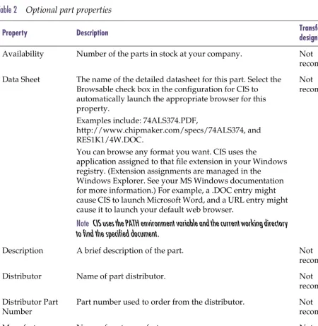
Table 2 Optional part properties
Property Description Transfer to
design?
Availability Number of the parts in stock at your company. Not
recommended
Data Sheet The name of the detailed datasheet for this part. Select the Browsable check box in the configuration for CIS to automatically launch the appropriate browser for this property.
Examples include: 74ALS374.PDF,
http://www.chipmaker.com/specs/74ALS374, and RES1K1/4W.DOC.
You can browse any format you want. CIS uses the
application assigned to that file extension in your Windows registry. (Extension assignments are managed in the Windows Explorer. See your MS Windows documentation for more information.) For example, a .DOC entry might cause CIS to launch Microsoft Word, and a URL entry might cause it to launch your default web browser.
Note CIS uses the PATH environment variable and the current working directory to find the specified document.
Not
recommended
Description A brief description of the part. Not
recommended
Distributor Name of part distributor. Not
recommended
Distributor Part Number
Part number used to order from the distributor. Not
recommended
Manufacturer Name of part manufacturer. Not
recommended
Manufacturer Part Number
Part number used to order from the manufacturer. Not
Creating a part database
Table 2 Optional part properties (continued)
Property Description Transfer to
design?
PCB Footprint The PCB footprint name (from the footprint library) assigned to a part.
Note Unlike Schematic Part property names, you cannot use directory paths for libraries with PCB footprint names. If you use a path with a PCB footprint name, the footprint will not display in the CIS explorer’s footprint window.
You can assign multiple PCB footprints to a single part by entering them in the part’s footprint field in your part database and separating each footprint name with the multi-value delimiter.
Tip The default value of the multi-value delimiter is a comma. However, when setting administrative preferences during database configuration, you can change the character CIS recognizes as the delimiter to a colon, semi-colon, question mark, or vertical bar. For information, see Setting
administrative preferences on page 2-47.
Then, when you update your design’s part status, CIS can approve and make current a schematic part which has several acceptable footprint names. Also, if a database part has several different valid PCB footprints, you will be able to choose any one of them when you are placing parts from the database parts window. All the configured PCB footprints for the database part will be available from a drop-down list under the PCB Footprint property name.
Recommended
Price Part price. Use this information when selecting parts to
design for cost. Include this property in reports to get a cost roll-up of your design.
Not
recommended
Rating The maximum rating for the part (for example, maximum
voltage or power dissipation).
Optional
Tolerance The percent tolerance specified for the part. Optional
Setting the field format
CIS can work with database text and number format fields (known as the cell format in spreadsheets). As a general rule, set each database field (that is, each table column) to text format. CIS converts other database field formats, such as float, to text format when properties are transferred to placed parts.
Note
Use only ANSI SQL-92 compliant data types for your field formats.
If you use non-compliant data types, CIS may misinterpret property
values.
Using more than one table
CIS can reference more than one table or worksheet in your part database. For example, you can group your parts into several tables according to type. That is, you can place resistors in one table, ICs in another, capacitors in another, and the remaining parts in a fourth table. When you’re viewing database parts with CIS, each table has a unique view. You can arrange the column settings for each table independently, allowing you to view different properties for each.
Creating a part database from an existing design
You can also create a part database by extracting part properties from an existing Capture design using the CIS Bill of Materials command.
Tip
If your designs are created in another schematic capture program
that creates bills of materials for part properties, you can still create
a part database from an existing design. Follow the instructions
supplied with the program to create the appropriate bill of
materials file from your design. Then, use the bill of materials file
to create a part database based on that design.
You can obtain a wizard from the Orcad web site that automates this process. The wizard also automatically derives schematic part and source library information for the placed parts in your Capture schematic. If you use the manual procedure detailed here, you will have to manually reference your placed parts to your libraries.
Creating a part database
Consider the example in the following illustration. The Standard Bill of Materials dialog box lists a typical set of properties to extract from the design.
In the Output Format list, CIS lists a number of properties that will be extracted to the bill of materials. You can add to this list by selecting properties from the Select
Properties list and clicking the Add button. You can remove properties from the Output Format list by selecting them and clicking the Remove button.
When you click OK in the Standard Bill of Materials dialog box, CIS creates a file with the property information for all the parts in the design. You can directly import this file into your database.
Extracting ERP or MRP database part information
You can also extract information from an existing enterprise or manufacturing resource planning (ERP or MRP) database, to create a part database. Save the ERP or MRP database as an ASCII file, then use that file as your part database file or as a source for a true part database file (for example, an MS Access format file).
Note
If your ERP database is ODBC compliant, you may not need to
extract part information. Instead, you should be able to directly
connect your preferred part database (PPD) to the ERP database–
you should not have to set up and run regular batch routines to
update the data in your PPD. For information about connecting
these databases, see the product documentation for both database
applications.
You may need to enhance the information in an ERP or MRP database, since it generally will not include everything required for schematic design. However, an ERP or MRP database usually contains a complete list of your company’s parts, part numbers, part descriptions, costs, quantities in stock, lead times, manufacturers, and alternate manufacturers.
Often, the data in an ERP or MRP database exists in a format that does not lend itself to ease of use. For example, the part value may be merged with the description, such as:
RES 1K 5% 1/4W
This makes searching for parts more difficult. If you can, split this information out in the ERP or MRP database into separate database properties, such as Part Type, Value, Tolerance, and Rating.
You can also contact the Cadence Methodology Services group for assistance in converting your data into a more convenient format.
Setting up the ODBC data source
Setting up the ODBC data source
Before you can set the CIS configuration, you must define the open database connectivity (ODBC) data source for your database. CIS interfaces to your part database using a defined ODBC data source name. A data source consists of a database filename and an associated ODBC driver with which to access it. If you are setting up a client-server database, the data source also references the database server. You define the data source name, assign the database file name, and specify the ODBC driver using the 32-bit ODBC Windows control panel.
To set the data source for the local database
1 From the Windows Settings menu, choose Control Panel.
2 Double-click on the ODBC icon. Depending on your system configuration, Windows displays the ODBC Data Source Administrator or a Data Sources dialog box.
Note
If you do not see an icon for 32-bit ODBC, run the Capture CIS
installation program to install ODBC.
You must define the data source on each user’s system. When you do so, use the same data source name. This allows users to share the same configuration file.
Note If your workgroup is sharing a configuration file, make sure to write-protect the file.
3 Click the ODBC Drivers tab and make sure the driver appropriate to your database or spreadsheet is installed on your system.
4 Click the User DSN tab then choose the Add button. Windows displays the Create New Data Source dialog box.
If the driver for your application is not present, you must install it. Check the CIS installation disk or contact the database or spreadsheet program supplier.
Setting up the ODBC data source
5 Choose the appropriate driver for your program (Microsoft Access, in this example), then click the Finish button.
6 Assign a name for the data source. If desired, enter a description for the data source name.
Note
Step
7may be different depending on the type of program you
used to create your database.
7 Under Database, click the Select button, and locate the database.
8 Click the Options button, and clear the Read Only check box so users can create new parts and add them to the database using CIS.
9 Click OK to set the data source.
Creating a configuration file
CIS requires a configuration (.DBC) file to make use of your part database. The configuration file:
• Identifies the ODBC data source to use as the part database and specifies the tables to use within that database.
• Identifies the part properties that are transferred to your design when you place or link a database part. • Sets the visibility for each of the transferred
properties.
• Contains the part type associations.
Note
If you use a CIS v7.2 configuration file with CIS Release 9, the file
will be updated to support the new features of this release. After
CIS updates the file, though, you cannot use it again with CIS v7.2.
If you are using a configuration file from before CIS v7.2, you must
recreate the file because the configuration file format was changed
for CIS v7.2.
When creating a configuration file, you should use the database configuration wizard. Completing the wizard guarantees that your part database can be used with most CIS features. For information about using the wizard, see
Using the database configuration wizard below.
However, if you need to use the manual method of creating a configuration file, you can reference Creating a configuration file manually on page 2-32.
Using the database configuration wizard
You can use the database configuration wizard each time you want to create a new database configuration file. The wizard is designed to make sure that you set at least the minimum table and property configuration that is required for CIS to work with your part database. Keep the configuration (.DBC) file in a
read-only directory that is accessible to all CIS users. You should make the directory read-only to prevent users from inadvertently changing the configuration.
Creating a configuration file
However, the wizard does not include all the options available to you, including options to optimize the performance of CIS and customize your CIS work environment. For this reason, when you have finished running the wizard, you should read through the last two parts of this section, Setting other part database options on page 2-30 and Setting other configuration options on page 2-32.
Starting the database configuration wizard
You can start the database configuration wizard anytime you want to create a new database configuration file.
To start the database configuration wizard
1 Open a new or existing schematic design in Capture.
3 Click the New button. CIS displays the Database Configuration Wizard.
Creating a configuration file
5 Click the Finish button. CIS displays the Configure Database dialog box and the wizard is complete.
6 If you want to set other part database options, complete the next section, Setting other part database options.
Setting other part database options
You can set other part database options that are not available in the database configuration wizard, including: • The part properties to be checked against the part
database when you update the part status of a design. CIS sets which properties are checked by default but, if you have a special situation that requires different properties to be checked, you are allowed to change the defaults.
• The part tables that CIS will search when you are linking placed parts to database parts. This is useful when your database consists of several part tables that are organized by device type (for example, capacitors in one table, resistors in another, and so on). When you are linking database parts to placed parts, CIS uses allowed part reference prefixes to limit your search to the appropriate tables. The result is that your search takes less time.
Creating a configuration file
To set other part database options
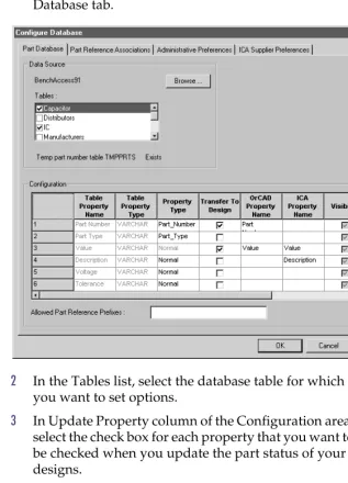
1 In the Configure Database dialog box, select the Part Database tab.
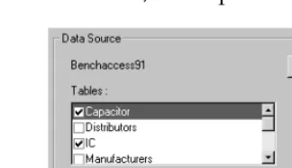
2 In the Tables list, select the database table for which you want to set options.
3 In Update Property column of the Configuration area, select the check box for each property that you want to be checked when you update the part status of your designs.
4 In the Allowed Part Reference Prefixes text box, type the part reference prefixes you want CIS to use to limit searches on the database table.
5 Repeat this procedure on each database table for which you want to set these options.
6 If you do not want to set any other part database or configuration options, click OK to save the new database configuration file.
For example, if a table contains only capacitors, you could enter C as the allowed part reference prefix. Then, when you choose the Link Database Part command, CIS searches that table only when the placed part you are linking has a part reference prefix of C.
[image:43.612.62.380.110.551.2]7 If you want to set other configuration options, go to the next section, Setting other configuration options.
Setting other configuration options
You can set other options in the database configuration that customize how CIS interacts with your part database and how you use CIS in your work environment. These options include:
• Defining part reference associations to improve the speed and accuracy of the search for database parts to link to placed parts. For more information, see
Defining part reference associations on page 2-43.
• Setting administrative preferences to customize some CIS features for your work environment. For more information, see Setting administrative preferences on page 2-47.
• Setting ICA supplier preferences to specify which component suppliers you want CIS to search for part pricing and availability. For more information, see
Setting ICA supplier preferences on page 2-50.
Creating a configuration file manually
You can create a configuration file using the manual procedure below. When you are finished creating the file, you will need to set the options for the file so that CIS knows how to handle your database table part properties. For information about setting or editing configuration file options, see Editing a configuration file on page 2-36.
Creating a configuration file
To create a configuration file manually
1 Open a new or existing schematic design in Capture.
3 Click the Setup button. CIS displays the Configure Database dialog box.
Creating a configuration file
5 Select the data source name you defined for your ODBC driver, then click OK. The Configure Database dialog box lists the tables found in your data source.
Editing a configuration file
As you set up and work with CIS, you may discover performance issues or elements of the CIS work
environment that are not optimal for your work group. This section describes in detail all the configuration options that are available and how to set them optimally for your situation. The four categories for these options include:
• Setting database table property options on page 2-36. • Defining part reference associations on page 2-43. • Setting administrative preferences on page 2-47. • Setting ICA supplier preferences on page 2-50.
Setting database table property options
Once you have created a database configuration file, you need to set the options for the file so that CIS knows how to handle your database table part properties.
To set database table property options
1 Open a new or existing schematic design in Capture. For information about creating a
Editing a configuration file
2 From the project manager’s Options menu, choose CIS Configuration. CIS displays the CIS Configuration File dialog box.
3 Choose a configuration file to edit by doing one of the following:
• To edit the current configuration file, click the Setup button.
CIS displays the Configure Database dialog box.
4 If you want to choose a new data source for your configuration, do the following:
Editing a configuration file
a Click the Browse button. CIS displays the Browse Data Source dialog box.
5 If you want to configure table properties, select the table that contains the properties. In the graphic below, the Capacitor table is selected.
When you select a table, the Configuration area lists the properties it contains. Each row represents a part property, and each property has the following characteristics:
Table Property Name.
This is the name of the property as it is defined in the part database.Table Property Type. This is the data type for the
property. Most properties are type Text, but there may be other data types.Property Type.
The Property Type determines how CIS interprets the property. Your database must include a property of type Part_Number in every table.Set the following property types:
• The Part_Type type for the database property that defines the part type. (This defines the field for folder view in CIS explorer.)
• The Schematic_Part type for the database property that contains the schematic part (symbol) name. • The PCB_Footprint type for the database property
that contains your Layout footprint name. If you want the database to include footprints not generated by Orcad Layout, set the property type to Normal. This prevents the footprint viewer from trying to interpret them.
Editing a configuration file
• The PSpice_Model type if you have a database property that contains PSpice Models. When you set this property type, CIS activates Pspice functionality for placed parts with a value for the database property.
• The Activepart_ID type if you have a database property to store the unique identifiers for parts that are placed using the activeparts web site through the ICA. When you set this property type, you can create reports about parts using the latest information from the activeparts database. In addition, you can view the latest information for a part directly from an instance on a schematic page.
Transfer To Design.
Setting this option (by selecting the appropriate check box) causes CIS to transfer the property along with the part when the part is placed or linked to a schematic part.Caution
CIS will not work unless you transfer at least the table property
names for the part number and value properties.
Orcad Property Name.
This defines the name of the property when it is transferred to the placed part. By default, it uses the name of the property as it appears in the database. Note that the Orcad Property Name applies only to properties for which you have enabled the Transfer to Design option.ICA Property Name. This maps property names on
new parts created with the internet component assistant (ICA) to corresponding database property names.Visibility. This sets the default visibility of the
property when it is copied to the placed part. There are four visibility modes:
Visible. CIS displays the property with the
part on the schematic page.Invisible.
CIS does not display the property with the part on the schematic page.Example: If the property name in the database is Component Tolerance and you want to call it Tolerance on the placed part, type Tolerance or choose Tolerance from the drop-down list.
No Change.
CIS does not modify the property visibility. If the property does not exist, it is set to invisible. You can override the default visibility for specific parts when you place or link database parts. Cells that you cannot change are shown with a light gray background in this column.Non-adjustable.
CIS does not allow this property to be set as visible on schematic pages.Key.
This sets the property as a key during the initial part search. The key is used when you are linking a database part to a previously placed part. Normally, you set only the Value property as a key so that, when you want to link a part, CIS searches the part database for parts with a specific value. If you don’t have a Value property in your database, do not set a key.Browsable.
This sets browse capability for theproperty. It allows you to put references to datasheets, drawings, and documents in your part database. For example, you can reference Adobe Acrobat (.PDF) files, Microsoft Word (.DOC) files, and even
worldwide web addresses (URLs). You can then view these items online in CIS when browsing the part database. They are also browsable when you are viewing standard CIS bills of materials.
You can browse any format you want. CIS uses the application assigned to that file extension in your Windows registry. (Extension assignments are managed in the Windows Explorer.) For example, a .DOC entry might cause CIS to launch Microsoft Word, and a URL entry might cause it to launch your default web browser.
Note
CIS uses the PATH environment variable and the current
working directory to find the specified document.
Update Part Property.
Select this if you want the value of this property for placed parts to be checked against the database part’s value when you update the part status of your design.For more information about placing and linking database parts, see Placing a database part on a schematic page on page 3-66 and Linking a placed part to a database part on page 3-88.
Editing a configuration file
6 (Optional) Type the part reference prefixes in the Allowed Part Reference Prefixes text box.
This is useful when your database consists of several part tables that are organized by device type (for example, capacitors in one table, resistors in another, and so on). When you are linking database parts to placed parts, CIS uses allowed part reference prefixes to limit your search to the appropriate tables. The result is that your search takes less time.
For example, if a table contains only capacitors, you could enter C as the allowed part reference prefix. Then, when you choose the Link Database Part command, CIS searches that table only when the placed part you are linking has a part reference prefix of C.
7 Repeat steps5 and 6 for each table in the database.
8 When you are finished configuring table properties, click OK or choose another tab to continue configuring your database.
Defining part reference associations
Part reference associations are used to improve the speed and accuracy of the search for database parts to link to placed parts. You create associations between a particular part type and the prefixes in the part database for that part type. For example, you can create a part reference
association for resistors such that all resistors in the part database use the R prefix.
Note
Defining part reference associations only improves part search
speeds for true databases (for example, Microsoft Access)—there
is no speed improvement from setting up associations if you are
using a spreadsheet or a text file for your database.
Note
Leave this box blank if you want the table to be searched
regardless of the part reference prefix.
For more information about linking database parts, see Linking a placed part to a database part on page 3-88.
Once you’ve defined part reference associations for your database, when you choose the Link Database Part command, CIS displays database parts of the appropriate type. Without defined part reference associations, CIS displays all parts in the database that match the keyed property value, regardless of the part type. By defining an appropriate reference association, you can limit the number of parts that CIS displays.
Note
Defining part reference associations is optional. You can define
associations later if you need to improve the search performance
during database part linking.
When you define part reference associations for your part database, keep the following points in mind:
• Part reference associations apply to all database tables. • The Part Type Property Contents value in the dialog
box is case-sensitive.
• You can associate one prefix with several different part types.
• An association applies to its level in the part type hierarchy and all lower levels.
• A part reference prefix without a defined part type association can be matched to any part type in the database.
• If a particular part in the database does not have its Part Type property contents defined, that part will be matched only to part reference prefixes with no defined part type associations.
Example: If you select an inductor, L1, on the schematic page with a value of 100uH, then choose the Link Database Part command, CIS displays all parts in the database having a value of 100 x 10-6. This may include capacitors, inductors, or other parts with a similar value.
By defining a reference association between inductors and the L prefix, you can limit the parts that CIS displays to inductors only.
Example: An association between the part reference prefix C and the part type Capacitor applies to part types of Capacitor, Capacitor\Electrolytic, and
Capacitor\Ceramic\Fixed. Note that a part reference prefix associated with the part type Capacitor\Ceramic does not apply to part types of Capacitor or
Editing a configuration file
To define part reference associations
1 In your local preferred parts database, make sure that the Part Type property field is indexed.
2 If you are not already in the Configure Database dialog box, do the following:
a Open a new or existing schematic design in Capture.
b From the project manager’s Options menu, choose CIS Configuration. CIS displays the CIS
Configuration File dialog box.
c If necessary, click Browse to locate the database configuration file you want to setup.
d Click Setup. CIS displays the Configure Database dialog box.
You can add icons for custom part references that will automatically display in the Part Reference column of the part manager window. Add your custom icons to the standard icons used for the Part Reference column located in the directory: ORCAD\CAPTURE\VENDOR
Each icon’s filename corresponds to a part reference prefix (for example, the icon for the part reference prefix R is stored in R.BMP).
3 In the Configure Database dialog box, choose the Part Reference Associations tab.
4 Enter a part type in the Part Type Property Contents column and a corresponding part reference prefix (or set of prefixes) for that part type in the Applicable Part Reference Prefixes column. Separate prefix entries with commas.
5 Click OK or choose another tab to continue configuring your database.
Editing a configuration file
Setting administrative preferences
Administrative preferences allow you to customize some CIS features for your work environment.
To set administrative preferences
1 If you are not already in the Configure Database dialog box, do the following:
a Open a new or existing schematic design in Capture.
b From the project manager’s Options menu, choose CIS Configuration. CIS displays the CIS
Configuration File dialog box.
c If necessary, click Browse to locate the database configuration file you want to setup.
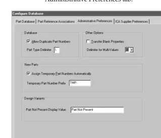
2 In the Configure Database dialog box, choose the Administrative Preferences tab.
3 Select the Allow Duplicate Part Numbers check box to allow the same part number to appear more than once in the database.
4 In the Part Type Delimiter text box, type the character that indicates a hierarchical level within a path in the database. Normally, the delimiter is a backslash (\) character.
5 Select the Transfer Blank Properties check box to create a property on the placed part even if the database part property does not have a specific value. This is useful if all your database parts are in a single table since, in that case, you will have properties in the table which are not relevant to certain types of parts.
6 If you want to use a character other than a comma to separate multiple field values in your database, If you want a database part to work with
[image:60.612.156.475.92.366.2]two or more different layout footprints, you can enter multiple PCB footprint names in your part database. For more information, see the PCB Footprint property entry in Table 2 on page 19.
Example: The database could have part types Capacitor\Electrolytic and Capacitor\Ceramic.
Editing a configuration file
choose another character from the Delimiters for Multi-Values list. For information about entering multiple values for part properties in your part database, see the Schematic Part (Symbol) property description in the Required part properties table on page 16.
7 Select the Assign Temporary Part Numbers
Automatically check box so that CIS will create and track temporary part numbers for you. That way when you create a new part, CIS automatically assigns a temporary part number to that part and enters the part number into the part record in the database as well as in a special table named TMPPRTS.
8 In the Temporary Part Number Prefix text box, enter the prefix to use for temporary part numbers. CIS automatically increments the temporary part number each time you create a new part. The temporary part number is then appended to this supplied prefix.
9 In the Part Not Present Display Value text box, enter the text description that you want CIS to use for variant parts set to Not Present. The property is displayed in the following locations:
10 Click OK or choose another tab to continue configuring your database.
Caution
CIS automatically creates the TMPPRTS table. Do not remove,
rename, or modify the structure of this table or temporary
part number tracking will not operate properly. Also, never
remove temporary part records, even after you have assigned
them approved part numbers. If you do, designs that have not
yet been updated with the new part numbers will have to be
updated manually.
• Part Number and Value fields in the part manager • Design variant columns in variant reports
• Variant parts on schematic page previews and printouts. For information about design variants, see the CIS online help.
To promote a temporary part to an approved part, do the following:
1 Using your database application, enter the approved part number in the TMPPRTS table next to the corresponding temporary part number.
2 Replace the temporary part number with the approved part number in the part table.
CIS automatically monitors the TMPPRTS table and notifies you if a temporary part in the design has been promoted to an approved part.
If your workgroup is using a shared, read-only database configuration file, all users must use the same temporary part prefix.
Setting ICA supplier preferences
ICA supplier preferences allow you to specify which component suppliers you wish CIS to search for part pricing and availability.
To set ICA supplier preferences
1 If you are not already in the Configure Database dialog box, do the following:
a Open a new or existing schematic design in Capture.
b From the project manager’s Options menu, choose CIS Configuration. CIS displays the CIS
Configuration File dialog box.
c If necessary, click Browse to locate the database configuration file you want to setup.
Editing a configuration file
2 In the Configure Database dialog box, choose the ICA Supplier Preferences tab.
3 In the list on the left, select the name of a supplier to be added to the list on the right, and click the Add button.
or
In the list on the right, select the name of a supplier to remove, and click the Remove button.
4 In the list on the right, select a supplier name, and use the arrow buttons to move the supplier higher or lower in the order of preference.
5 Click OK or choose another tab to continue configuring your database.
Note
The internet component assistant only shows information for
the first supplier that has the part you want, in the order of the
preference you set here.
Saving the configuration file
1 (Optional) In the CIS Configuration File dialog box, choose Save As to save the configuration for future use.
Setting up the ICA to access external part data
Setting up the ICA to access
external part data
Note
Internet Explorer 4 or higher must be installed on your system for
the internet component assistant (ICA) to run.
Setup of the ICA is handled during the Capture CIS installation process. CIS uses the Cadence product registration number to control your access to the ICA. You enter the registration number when you install Capture CIS.
Creating Crystal Reports
templates
You can use Crystal Reports in conjunction with CIS to make customized report templates with more advanced features than the standard CIS bill of materials, including precision formatting and formulas that total, filter, and analyze data for highly specific results. When you create customized Crystal Reports templates, you can use all of the part properties included in your preferred parts database and your individual design projects.
Note
You must have Crystal Reports Designer installed on your system
with CIS to create Crystal Reports templates. If you do not own a
copy of Crystal Reports Version 6 or 7, visit Orcad’s web site at
www.orcad.com for reseller information.
Once you have created Crystal Reports templates, any CIS user with access to them can generate, preview, print, and export reports with their design’s database part
information from within CIS. They will not need to have copies of Crystal Reports installed locally on their workstations to use these templates.
This is the process you will complete to create your Crystal Reports templates:
1 Create an Access database bill of materials (.MDB) file using a standard CIS bill of materials.
2 Create report template (.RPT) files in Crystal Reports using the Access database file.
3 Store the Crystal Reports template files where CIS can use them.
To create an Access database (.MDB) file for use by Crystal
Reports
1 Open a new or existing schematic design in Capture. Crystal Reports is a widely-used report
design software produced by Seagate Technology, Inc.
If you want to make a standard CIS bill of materials template, see Creating a standard CIS bill of materials on page 4-104.
You only need Crystal Reports software to create templates, not to use them. For this reason, you only need to buy one copy of the software for your entire workgroup.
Creating Crystal Reports templates
2 From the project manager’s Reports menu, point to CIS Bill of Materials and choose Standard. CIS displays the Standard Bill of Materials dialog box.
3 In the Template Name text box, type in a name for the report (for example, Report for Crystal Reports template).
4 In the Select Properties list on the left, double-click each of the part properties until all of them are moved to the Output Format list on the right.
5 Click OK. The report may take several minutes to generate.
6 From the File menu, choose Save As. CIS displays the Save As dialog box.
7 In the Save As Type list, select Access format (*.MDB).
8 Specify the file name and location and click OK.
To create a Crystal Reports template
Note
You must have Crystal Reports Designer installed on your system
with CIS to create Crystal Reports templates. If you do not own a
copy of Crystal Reports Version 6 or 7, visit Orcad’s web site at
www.orcad.com for reseller information.
1 Using Crystal Report Designer, create a custom report using the Access database bill of materials (.MDB) file as your data file.
To store a template file for use by CIS
1 Store your Crystal Reports template (.RPT) file where all users in your workgroup have access to it.
To avoid having to browse for your template, store the file in the same directory as your database configuration (.DBC) file. The template will automatically appear in the Crystal Reports Bill of Materials dialog box.