ISSN Print: 2164-0165
DOI: 10.4236/mme.2018.84016 Nov. 9, 2018 233 Modern Mechanical Engineering
Pure Condition of Both 6R Serial and 3-PRS
Parallel Robots Using Grassmann-Cayley
Algebra
Luc Djimon Clément Akonde
1*, Alain Adomou
2, Tognon Clotilde Guidi
21Département du Génie Industriel et Maintenance (GIM), Institut Universitaire de Technologie (IUT) de Lokossa, Université Nationale des Sciences, Technologies, Ingénierie et Mathématiques (UNSTIM), d’Abomey, Benin
2Institut Universitaire de Technologie (IUT) de Lokossa, Université Nationale des Sciences, Technologies, Ingénierie et Mathématiques (UNSTIM), d’Abomey, Benin
Abstract
This research presents Pure Condition approach, which has used in analyzing simultaneously the singularity configuration and the rigidity of mechanism. The study cases analysis is implemented on variable joints orientation of 6R (Revolute) Serial Manipulators (SMs) and variable actuated joints position of 3-PRS (Prismatic-Revolute-Spherical) Parallel Manipulators (PMs) using Grassmann-Cayley Algebra (GCA). In this work we require in Projective Space both Twist System (TS) and Global Wrench System (GWS) respectively for serial and parallel manipulators which represent the Jacobian Matrix (J) in symbolic approach to Plücker coordinate vector of lines and unify framework on static and kinematics respectively. This paper, works, is designed to de-termine geometrically at symbolic level the vanished points of inverse form of this Jacobian Matrix (J) which called superbracket in GCA. The investigation vary to those reported early by introducing GCA approach on the singularity of serial robot, variable joints orientation and actuated positions on robot manipulators (RMs) to analyze rigidity frame work and singularity configura-tion which involve simultaneously Pure Condiconfigura-tion. And the results also re-vealed a single singularity condition which contains all particulars cases and three general cases such as the shoulder, elbow and wrist singularity for SMs while double, single and undermined singularities respectively for 3-PRS, 3-PRS and 3-PRS PMs which contain all generals and particulars cases.
Keywords
Pure Condition, 6R SMs, 3-PRS PMs, Superbrackets, GCA
How to cite this paper: Akonde, L.D.C., Adomou, A. and Guidi, T.C. (2018) Pure Condition of Both 6R Serial and 3-PRS Parallel Robots Using Grassmann-Cayley Algebra. Modern Mechanical Engineering, 8, 233-248.
https://doi.org/10.4236/mme.2018.84016
Received: August 19, 2018 Accepted: November 6, 2018 Published: November 9, 2018
Copyright © 2018 by authors and Scientific Research Publishing Inc. This work is licensed under the Creative Commons Attribution International License (CC BY 4.0).
http://creativecommons.org/licenses/by/4.0/
DOI: 10.4236/mme.2018.84016 234 Modern Mechanical Engineering
1. Introduction
Pure Condition is a scalar value that is needed to identify both singularity con-figuration and rigidity of robot framework. Singularity of Serial robot arises when certain direction is unattainable and one or more Degree of Freedom (DOF) is loosed while the end-effector of Parallel robot becomes uncontrollable and gained more DOF. Rigidity of Robot framework preserves the length bar-joint which is lacked at singularity [1]. One classical approach to solve Pure Condition problem is determining where J is non-singular. In the past years, ex-tensive studies were carried out on analytically [2], algebraically [3] [4], kine-matical [5] [6], numerical [5] [7], geometrical [2] [8] and simulation [9] ap-proaches. Since Jacobian Matrix J is expressed in Plücker coordinate vector of lines [10] [11], recently experiments by S. Amine, S. Caro et al. [12] have sug-gested the geometric method associated with dependency of Plücker vector lines to get the determinant of Matrix J which is formulated in GCA language [10] [13]. On the basis of previous literature data, we intend to investigate pure con-dition of 6R SMs within variable orientated joints which TS is calculated before computing its superbracket while 3-PRS PMs within variable actuated joints: 3-PRS; 3-PRS and 3-PRS which GWS are calculated before computing their su-perbrackets decomposition. Interpretation of the vanishing condition of these superbrackets decomposition involves the robot pure condition.
The key contribution in this paper is a simultaneous determination of both singularity condition of Robots Manipulators and rigidity framework without algebraic calculus by Grassmann-Cayley Algebra approach. We shall calculate the determinant of the Jacobian Matrices in coordinate free manner by develop-ing and reducdevelop-ing the Superbracket expression. A novelty from other research is that Serial Robot in this paper is cheeked and investigated by Grassmann-Cayley Algebra.
This paper is organized as follows: Section 2 recalls mathematics background of projective space such as Plücker coordinate of vectors line, screw theory, twist system, Global Wrench System with their associate graphs before the concept of brackets which represent the Jacobian matrix used in GCA applied to robot ma-nipulators. Section3 describes respectively 6R SMs and 3-PRS PMs with their adopted representation. Section 4 focuses firstly on computing the TS of 6R SMs where all joints are simultaneous actuated and the GWS of 3-PRS PMs where the actuators are sequenced on prismatic, revolute or spherical joint. Secondly on the vanished condition of TS and GWS which represent the determinant of ma-trix J in GCA language. The interpretation, comparison and verification of these obtained results are discussed as the pure condition of robot. Finally, concluding and remarks are given in Section 5.
2. Mathematics of Robot Manipulator Using
Grassmann-Cayley Algebra
instan-DOI: 10.4236/mme.2018.84016 235 Modern Mechanical Engineering taneous motion of robot manipulators (RMs). Secondly brief notion of GCA is applied on robot manipulators to determine the Jacobian Matrix in bracket form. More details on GCA and superbrackets decomposition should refer to
[10]-[17].
First of all, the brief background information about this research is provided in the Diagram 1 below.
2.1. Projective Space Extended to Robot Motion
The projective space refers to the affine space augmented by the points at infini-ty where any pair of parallel lines can be said to meet at the unique point at in-finity on the plane Π∞. In projective space any point (line) has four (six)
ho-mogeneous coordinates and each line is called Plücker line which can be ex-tended to coordinates for the screws and the duality twist-wrenches in applica-tion for kinematics of robot manipulators [12]. A finite line, L, is represented by its Plücker coordinates vector F:
(
;)
F= s r s× (1) where s is the line direction,
(
r s×)
represents the moment of L with respect to the origin and r is the position vector of any point on L. An instantaneous screw axis is a Plücker coordinate vector line with it associated pitch in a given posi-tion, then the screw axis of PMs is described by:(
0)
ˆ$=s s s; × +hsT (2)
DOI: 10.4236/mme.2018.84016 236 Modern Mechanical Engineering with, s the unit vector along the screw axis, s0 the position vector of a point on
the screw axis with respect to a reference frame, h the pitch of the screw. A zero pitch screw ˆ$0 and an infinite pitch screw ˆ$∞ can be respectively identified
with a Plücker coordinate vectors of a finite line and a line at infinity:
(
)
0 0
ˆ$ =s s s; × T (3)
[ ]
ˆ$∞ = 0;sT (4) Since n number of independents kinematic chains form (n)screw space which is composed of (n)system screws, all screws which are reciprocal to a (n)system screws form (6-n)system. Two zero pitches screws, ˆ$0 and ˆ$0′, are reciprocal
to each other if and only if their axes are coplanar. A zero pitch screw ˆ$0 is
re-ciprocal to an infinite pitch screw ˆ$∞ if only if their directions are orthogonal
to each other. Two infinite pitch screws ˆ$∞ and ˆ$∞′ are always reciprocal to
each other. A body instantaneously undergoing a pure rotation about an axis l is a twist of zero pitch ˆ$0. A body instantaneously undergoing a pure translation
along an axis l is a twist of infinite pitch ˆ$∞. A manipulator subjects to a pure
force along the axis l is a wrench of zero pitch screw ˆ$0. A body subject to a
pure couple is a wrench of infinite pitch screw ˆ$∞. In robotics; wrench is a
screw representing a combination of a force and a couple acting on a manipula-tor [12].
2.2. Twist System (TS) and Global Wrench System (GWS)
Twist Space of a serial kinematic chain is the support of the join extensors that represents the twist spaces, and then the Twist System Ti of a serial kinematic
chain composed of k joints extensors is described as [17]: 1 2
i k
T =T ∨T ∨∨T (5) Similarly, the Wrench Space of a parallel kinematic chain is the support of the join extensors that represents the wrench spaces and then the Wrench System Wn of an n parallel kinematic chain composed of m serial chains is described as
[17]
1 2
i n
DOI: 10.4236/mme.2018.84016 237 Modern Mechanical Engineering [18] and described as:
(
,)
(
$ , ,$ ,$ , ,$ˆ1 ˆ ˆn 1 ˆ6 n)
n i a a c cGWS= W F = − (7)
with
( )
1
system-actuated
ˆ ˆ
$ , ,$n
n a a
n
W = and
( )
1 6
6 system-constraint
ˆ ˆ
$ , ,$ n
i c c
n
F −
−
= . The det
( )
J is written in theGWS form as:
( )
[
]
( ) ( )
1 1
system 6 system
det , , n, , , i
n n
J GWS W W F F
− = =
(8)
The bracket of these vectors is defined as the determinant of matrix having i
w as its columns and described as:
[
1 2]
1,1 1,2 1,,1 ,2 ,
, , , det
k
k
k k k k
x x x
w w w
x x x
=
(9)
The determinant GCA in language represents the symbolic approach of Plücker coordinate lines and is used to analyze the pure condition without alge-braic coordinates. In consequence, the system is linearly dependent when:
[
]
1 2 k 1, , ,2 k 0
w w∨ ∨ ∨ w = w w w = (10)
3. Description and Adopted Representation of both 6R SMs
and 3-PRS PMs
3.1. Description and Adopted Representation of 6R SMs
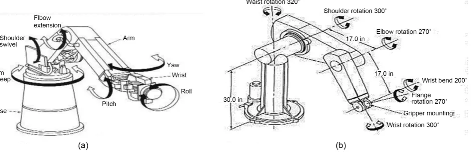
The 6R SMs consist of seven links li i(=1,2, ,7 ) connected in succession by six
re-volute joints (Figure 1). The link li fixed to the ground in a fixe frame
(
1 1 1)
O x y z while the last three non-coplanar axis intersect at a unique common point h. The revolute axis Zi are respectively the joint axis of li and li+1 where
1,2, ,6
i= ; Z1 is perpendicular to both Z2and Z3, Z2 and Z3 are parallel. Z4, Z5
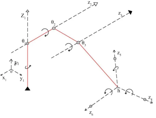
and Z6 are three no-coplanar intersecting axis at a unique point h (Figure 2). In
[image:5.595.71.541.552.708.2]projective space, we choose two points on each of these six joint axis centers:
DOI: 10.4236/mme.2018.84016 238 Modern Mechanical Engineering
Figure 2. Descriptions of 6RSMs.
, , , ,
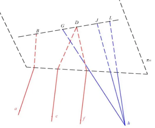
aB cD fE hG hJ and hL respectively on z z z z z1, , , ,2 3 4 5 and z6 (Figure 3).
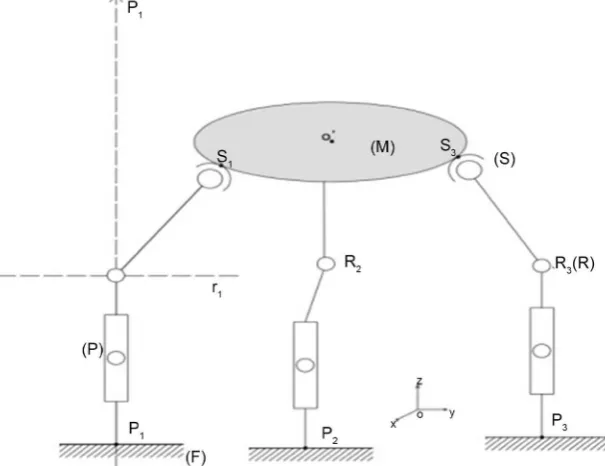
3.2. Description and Adopted Representation of 3-PRS PMs
Each independent li has five degrees of freedom (Figure 4). Express as one translation, one revolute and one spherical joint which is consist of three inter-secting and non coplanar rotations joints at S u v wi
(
i, ,i i)
The input of the me-chanism consists of three variable positions of the actuated joints defined as: Firstly the prismatic joints are actuated and all other joints are passive. Secondly the revolute joints are actuated and all other joints are passive. Thirdly the spherical joints are actuated and all other joints are passive. The axis pi of theprismatic joint and the following axis ri of the revolute joint are perpendicular.
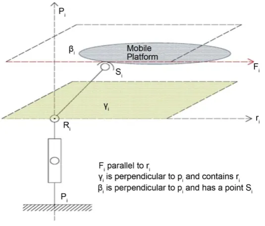
Let αibe the plane formed by the spherical joint center Si and the revolute joint
axis ri (Figure 5). Let βi be the plane which contains the spherical joint center Si
and perpendicular to the prismatic joint pi (Figure 5). Consequently αi and βi
intersect each over at a line Fi. Lines ab, ef and ij represent respectively F1, F2
and F3 while cd, gh, and kl represent respectively r1, r2 and r3. Thus each Fi
pa-rallel to each ri. Let γi be the plane formed by lines perpendicular to the
prismat-ic joint pi and coplanar to the revolute joint ri(Figure 6).
4. TS and GWS Computation Respectively for 6R SMs and
3-PRS PMs in Coordinate Free Manner
4.1. TS Computation for 6R SMs and Its Vanished Points in GCA
Approach without Algebraic Calculus
DOI: 10.4236/mme.2018.84016 239 Modern Mechanical Engineering
Figure 3. Adopted representation in projective space.
Figure 4. Descriptions of 3-PRS PMs.
see Equation (5). In projective space, any line is formed by two different points which can be either two different finite points or one finite point and one point at infinity. Therefore in this paper, Grassmann-Cayley Algebra applied to 6R serial robot involves the symbolic approach of these six Plücker coordinates fi-nite lines and lines at infinity are graphically represented as its Twist Wrench graph (Figure 7).
[image:7.595.221.524.325.558.2]DOI: 10.4236/mme.2018.84016 240 Modern Mechanical Engineering
Figure 5. Wenches space αi and βi.
Figure 6. Wenches space γi.
[
,0 , , , ,]
0T
aB cD fD hG hJ hL =
= (11)
This expression can be developed into 24 combination of linear monomials. Each of them represents the product for three brackets of four projective points. The useful tool, Graphic User Interface, provided by S. Amine, S. Caro et al. [12]
perform this calculus and gives the singularity condition:
[image:8.595.241.509.342.571.2]DOI: 10.4236/mme.2018.84016 241 Modern Mechanical Engineering
Figure 7. Twist graph of 6R SMs.
And then Equation (12) vanishes when at least one of the three monomials vanish.
If
[
aBDh]
=0 then: aB hD∧ means h lies either on aB or aBD. Ac-cording to the adopted representation h lies on one of:{
z z z1,(
1 2) (
, z z1 3)
}
witha particular case h z∈ 1: a shoulder singularity.
If
[
cfDh]
=0 then: cD hf∧ or fD hc∧ means h is either collinear to cD or fD since z2 and z3 are parallel lines and intersect in the projective spaceat infinity at point D, h must lies on a plane formed by z z2 3: it is a an elbow
singularity, the end effector is at the boundary of the workspace.
And at last if
[
GJhL]
=0 then hG LJ∧ or hJ LG∧ or hL GJ∧ , means4
z ∧LJ or z5∧LG or z6∧GJ, it is obvious that we are in wrist singularity condition and the last three axes z z z4, ,5 6 must be parallel to each over: This
condition is impossible to implement practically: except that the wrist design was modified. Two of the last three axis must be parallel to each over.
4.2. GWS Computation for 3-PRS PMs and Its Vanished Points in
GCA Approach without Algebraic Calculus
Each limb li of a 3-PRS PMs consist of five serial kinematic chains, a twist Ti of each limb li form 5-system. Instantaneously the composition of these five serial twists corresponds to their simple addition in the projectiv space (Equa-tion (13) [10] [12] [17]
( ) ( ) ( ) ( ) ( )
$ˆ $ˆ $ˆ $ˆ $ˆi
pi ri ui vi wi
T = + + + + (13)
with ˆ$pi =
[
0,pi]
T; ˆ$ri =r R ri,(
i× i)
; ˆ$ui =u S ui,(
i× i)
; ˆ$vi =v S vi,(
i× i)
;(
)
DOI: 10.4236/mme.2018.84016 242 Modern Mechanical Engineering 4).
In this paper, each serial limb, PRS PMs has five degree of freedom while the closed chain of the 3-PRS fully PMs has only three. This means the limbs con-strained the mobile platform by three degree of freedom when each limb is dri-ven by one actuator. The mechanism supposes to be constrained when it is acti-vated and may be stressed at some critical poses.
Constraint wrench system Fi, the reciprocal constraint wrench system to all (5)system twist Ti form a (1)ystem constraint wrench of zero pitch. This
con-straint wrench system Fi of each limb li is defined as a line force passing through the center of the spherical joint Si along the direction parallel to the revolute joint ri [10] [17].
(
)
,
i i i i
F =r S r× (14)
Actuated wrench system
When the actuated prismatic joint of li is locked, only 4-system twist is valid. Consequently each prismatic actuated wrench, Wi, of each li form 2-system wrench and only reciprocal to all passive 4-system twist $ ,$ ,$ˆ ˆ ˆri ui vi and ˆ$wi. Then all reciprocal screws lie on a plane αi (Figure 5) [10] [11]. When the ac-tuated revolute joint of li is locked, only 4-system twist is valid. Consequently each revolute actuated wrench, Wi′, of each li form 2-system wrench and only reciprocal to all passive 4-system twist $ ,$ ,$ˆ ˆ ˆpi ui vi and ˆ$wi.Then all reciprocal screws lie on a plane βi (Figure 5) [10] [11]. Spherical joint correspond to the three intersecting and no-coplanar revolute joints, when each actuated spherical joint of each limb PRS is locked, only 2-system twist will be valid for each limb PRS. Consequently each spherical actuated wrench, Wn, of each limb-PRS form
4-system wrench and only reciprocal to all remain passive 2-system twist ˆ$pi and ˆ$ri [10] [11]
Global Wrench System of 3-PRS PMs
Each limb li is identified by Fi and Wi.Both graphical representation of GWS is called wrench graph
For: 3-PRS (Figure 8)
(
)
[
]
6 6
1 2 3 1 2 3
det
, , , , , with i i
J GWS
GWS α α α F F F F α
× =
= ∈ (15)
Each Fi and ri are parallel, in projective geometry they intersect each over at infinity at a unique point. Then b d f h≡ , ≡ and j l≡ respectively for limbs l l1 2, and l3. For notation convenience, let designed by the capital letters
these points at infinity and rewrite Equation (15) as:
[
, , , , ,]
andGWS= aB cB eF gF iJ kJ P aB cB eF gF iJ kJ= ∨ ∨ ∨ ∨ ∨ (16) The Superbracket in Equation (16) is decomposed, reduced [12] and gave:
[
]
[
][
][
] [
][
][
]
[
][
][
] [
][
][
]
, , , , ,
aB cB eF gF iJ kJ
aBce BgFJ FikJ aBcF BgFJ eikJ aBcg BeFJ FikJ aBcF BeFJ gikJ
= + −
− +
DOI: 10.4236/mme.2018.84016 243 Modern Mechanical Engineering
Figure 8. Wrench graphs of PRS.
Equation (17) vanishes at singularities configuration with the condition:
[
aB cB eF gF iJ kJ, , , , ,]
=0 when[
xBFJ]
=0 oraBc ikJ eF∧ ∧ (18){
, , , , , ,}
x= a b c e g i k , in singular configuration:
[
xBFJ]
=0 or aBc ikJ eF∧ ∧ If[
aBFJ]
=0 then aB FJ∧ means F collinear to aB or J collinear to aB. Since F and J are respectively the unique intersecting point at infinity of parallel lines eF gF, and iJ kJ, then F collinear to aB or J collinear to aB which means aB intersect also eF gF iJ, , and kJ at F as infinity point. Since two parallel lines intersect each over at a unique point at infinity it is obvious that aB is parallel to eF gF iJ, , and kJ.This means F1 parallel to F W F W2 2 3 3.Similarly if
[
cBFJ]
=0 with the same processes, W1 Parallel to F W F W2, , ,2 3 3.For l1, the singularity occurs when F1 or W1 parallel to F F W W2, , ,3 2 3. It is
obvious to deduce for li. If aBc ikJ eF∧ ∧ means the line F2 crosses the
in-tersection line of the two planes α1 and α3
For 3-PRS (Figure 9)
(
) (
)
(
)
[
]
6 6
1 2 3 1 2 3
det
, , , , , with i i
J GWS
GWS β β β F F F F β
× ′
′ =
′ = ∈ (19)
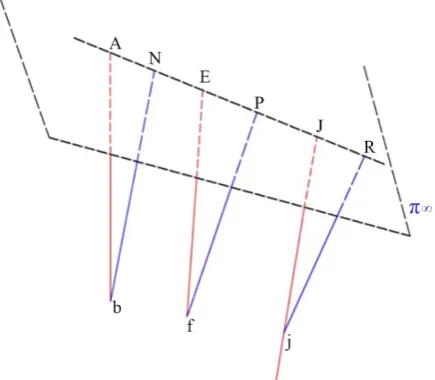
Any line can be represented in projective space by one finite point and one point at infinity, let choose one point at infinity on each of these six Plücker lines. Equation (19) can be rewrite as:
(
GWS)
′=[
Ab bN Ef fP Ij jR, , , , ,]
andP′=Ab bN Ef∨ ∨ ∨ fP Ij jR∨ ∨ (20)DOI: 10.4236/mme.2018.84016 244 Modern Mechanical Engineering
Figure 9. Wrench graph of 3-PRS PMs.
(
GWS)
′=[
Ab bN Ef fP Ij jR, , , , ,]
andP′=Ab bN Ef∨ ∨ ∨ fP Ij jR∨ ∨ (21) The Superbracket in Equation (21) decomposed and reduced with the given tool [12]:[
]
[
][
][
] [
][
][
]
[
][
][
] [
][
][
]
, , , , ,
Ab bN Ef fP Ij jR
AbNE bfPj fIjR AbNf bfPj EIjR AbNf bEfj PIjR AbNP bEfj fIjR
= − +
+ −
(22)
Equation (22) vanishes at singularities configuration with the condition:
[
Ab bN Ef fP Ij jR, , , , ,]
=0 when AbN bfj IjR EPf∧ ∧ ∧ The singular configu-ration arises when the four planes β β β1, ,2 3 and bfj intersect at a uniquepoint. For 3-PRS
(
) (
)
(
)
[
]
(
)
6 6
1 2 3 1 2 3
det
, , , , , with i i i,
J GWS
GWS γ γ γ F F F γ p r
× ′′
′′ =
′′ = ≡ (23)
Instead of 6 Plücker coordinates lines we found nine Plücker coordinates lines. This means in such situation, the frame rigidity of the mechanism has problem. Once the spherical actuator is locked the number of Plücker lines increase to two-9 extensor. Equation (23) confirms this absurdity. When the actuated spherical joint is locked the number n of degree of freedom becomes negative then “it is preloaded structure and no motion is possible and some stresses may also be presented at the time of assembly” [19]. The tool provides by Stéphane Caro et al. [12] can neither decompose nor reduce it.
4.3. Pure Condition Analysis in Grassmann-Cayley Approach
DOI: 10.4236/mme.2018.84016 245 Modern Mechanical Engineering to meet infinity joint rate requirement and the actuators will blow off. The actu-ating prismatic joints reached robot in singularity configuration when the ac-tuated force or the constraint force of any lk is parallel to either a constraint force or an actuated force of lk′ with k k≠ ′. Singular motion arises when the
common actuated force of l1 and l3 crosses the constraint force of l2. The
revolute actuated joints reached robot in singularity configuration when the four planes β β β1, ,2 3 and bfj intersect at a unique point. The common actuated
wrench of the three limbs crosses the plane formed by the three constraint forces at a point and then the robot manipulator is in a plane configuration. The spherical actuated joints give different form of the symbolic Plücker coordinates lines. Instead of 6 Plücker coordinates lines we found nine Plücker coordinates lines. Once the spherical actuator is locked the number of Plücker lines increase to two-9 extensor. Equation (23) confirms this absurdity. The results presented above show that firstly whatever wrist singularity is theoretical possible; practi-cally this singularity could be possible if only if the design of two of the last three axis are parallel. Secondly, when the spherical joint is actuated, the architecture mechanism becomes preload and stressed. This suggests that the rigidity of the manipulators depend of the position of the actuated joints in the mechanism. Thirdly, parallel robot or serial robot, the six legs bars have dependent Plücker coordinates when the architecture lacks rigidity in the critical pose. And the last but not the least, we suggested that the rigidity framework of the robots mani-pulators depends on both architecture structure and operating mode.
5. Conclusion
operat-DOI: 10.4236/mme.2018.84016 246 Modern Mechanical Engineering ing mode of the architecture. We recognize that the method adopted in current study does not cover all class of robot such as hybrid robot, hybrid parallel robot which will be our future research in the next paper. These results suggest that pure condition confirmed that both position and orientation of the actuator have to be integrated in the conceptual design stage in order to avoid singulari-ties configuration and to optimize the rigidity frame of the architecture. The analysis of robot pure condition is a practical problem of robot manipulators de-signers who need many mathematical theories such as Geometry Algebra, Lie Group theory; therefore Robotic field is a multidisciplinary field belongs to Me-chatronics applications.
Acknowledgements
I would thank Dr. (MC) Florent QUENUM, for his advice and encouragement during my research. I’m also grateful to Professor Stéphane CARO, to provide his graphic user interface for superbrackets computation.
Conflicts of Interest
The authors declare no conflicts of interest regarding the publication of this pa-per.
References
[1] Downing, D.M., Samuel, A.E. and Hunt, K.H. (2002) Identification of the Special Configurations of the Octahedral manipulator Using the Pure Condition. The In-ternational Journal of Robotics Research, 21, 147.
https://doi.org/10.1177/027836402760475351
[2] Hayes, M.J.D., Husty, M.L. and Zsombor-Murray, P.J. (2002) Singular Configura-tions of Wrist-Partitioned 6R Serial Robots: A Geometric Perspective for Users. Transactions of the Canadian Society for Mechanical Engineering, 26, 41-55.
https://doi.org/10.1139/tcsme-2002-0003
[3] Chen, Y.-C. and Chen, C.L.P. (1994) An Analysis to the Singularity of Serial Mani-pulator Using Reciprocal Screw Theory. IEEE International Conference on Systems, Man, and Cybernetics, Humans, Information and Technology, 1, 148-153.
[4] Boudreau, R. and Podhorodeski, R.P. (2010) Singularity Analysis of a Kinematically Simple Class of 7 Jointed Revolute Manipulators. Transactions of the Canadian So-ciety for Mechanical Engineering, 34, 105-117.
[5] Carretero, J.A., Podhorodeski, R.P., Nahon, M.A. and Gosselin, C.M. (2000) Kine-matic Analysis and Optimization of a New Three Degree-of-Freedom Spatial Paral-lel Manipulator. ASME. Journal of Mechanical Design, 122, 17-24.
[6] Tchoń, K. and Muszysńki, R. (1998) Singular Inverse Kinematic Problem for Ro-botic Manipulators: A Normal Form Approach. IEEE Transactions on RoRo-botics and Automation, 14, 93-104. https://doi.org/10.1109/70.660848
[7] Rocha, D.M. and da Silva, M.M. (2013) Workspace and Singularity Analysis of Re-dundantly Actuated Planar Parallel Kinematic Machines. Proceedings of the XV In-ternational Symposium on Dynamic Problems of Mechanics.
DOI: 10.4236/mme.2018.84016 247 Modern Mechanical Engineering Analysis and Design. A Geometrical Characterization of Workspace Singularities in 3R Manipulators. Springer Netherlands, 411-418.
[9] Selvakumar, A.A., Babu, R.P. and Sivaramakrishnan, R. (2012) Simulation and Sin-gularity Analysis of 3-PRS Parallel Manipulator. Proceedings of IEEE, International Conference on Mechatronics and Automation, 2203-2207.
[10] Kanaan, D., Wenger, P., Caro, S. and Chablat, D. (2009) Singularity Analysis of Lower Mobility Parallel Manipulators Using Grassmann-Cayley Algebra. IEEE Transactions on Robotics, 25, 995-1004. https://doi.org/10.1109/TRO.2009.2017132
[11] Amine, S., Tale-Masouleh, M., Caro, S., Wenger, P. and Gosselin, C. (2011) Singu-larity Analysis of the 4-RUU Parallel Manipulator using Grassmann-Cayley Alge-bra. CCToMM Symposium on Mechanisms, Machines and Mechatronics, Mon-treal.
[12] Amine, S. and Caro, S. Singularity Conditions of Lower-Mobility Parallel Manipu-lators Based on Grassmann-Cayley Algebra. L’Agence nationale de la recherche.
http://www.irccyn.ec-nantes.fr/~caro/SIROPA/GUIGCASiropa.jar
[13] Arvin, R. and Mehdi Tale, M. Singularity Configurations Analysis of a 4-DOF Pa-rallel Mechanism Using Grassmann-Cayley Algebra.
[14] Ben-Horin, P. and Shoham, M. (2009) Application of Grassmann-Cayley Algebra to Geometrical Interpretation of Parallel Robot Singularities. The International Jour-nal of Robotics Research, 28, 127-141. https://doi.org/10.1177/0278364908095918
[15] Amine, S., Masouleh, M.T., Caro, S., Wenger, P. and Gosselin, C. (2012) Singularity Conditions of 3T1R Parallel Manipulators with Identical Limb Structures Semaan. ASME Journal of Mechanisms and Robotics, 4, 1.
[16] Wen, K., Won Seo, T., et al. (2015) A Geometric Approach for Singularity Analysis of 3-DOF Planar Parallel Manipulators Using Grassman-Cayley Algebra. Cam-bridge University Press, Robotica, 1-10.
[17] Amine, S., Caro, S., Wenger, P. and Kanaan, D. (2012) Singularity Analysis of the H4 Robot Using Grassmann-Cayley Algebra. Robotica, 1-10.
[18] Staffetti, E. and Thomas, F. (2000) Kinestatic Analysis of Serial and Parallel Robot Manipulators Using Grassman-Cayley Algebra. In: Lenarcic, J. and Stanisic, M.M., Eds., Advances in Robot Kinematics, Springer Netherlands, 17-27.
https://doi.org/10.1007/978-94-011-4120-8_2
DOI: 10.4236/mme.2018.84016 248 Modern Mechanical Engineering
Nomenclatures
Symbols nomenclatures
∨: Join operator (in Grassmann-Cayley Algebra)
∧: Meet operator (in Grassmann-Cayley Algebra)
: Intersection of vectors ⊕: Spanning by vectors
i
F: Constraint wrench force of the ith limb for the Parallel Robot
σ: Permutation
ρ: Wrench intensity
, p q
Γ : Plücker coordinate vector of finite line passing through two distinct finite points p and q
∞
Γ : Plücker coordinate vector of lines at infinity, passing through two points at infinity
6 6
J× : Jacobian of Square Matrix of six columns six rows
k: Number of joint
i
l: ith Limb or ith kinematic chain
m: Number of link
η: Order of task space
3
P : Projective Space of 3 dimensional
s
P: Symbolic level of Plücker coordinates
i
p: Prismatic joint axis of ith limb
π∞: Plane at infinity in the Projective Space
i
r: Revolute joint axis of the ith limb
i
s: Spherical joint axis of the ith limb
0
S: Position Vector of any point on the screw axe S: Unit vector along the screw axis
0
ˆ$: Zero pitch screw
ˆ$∞: Infinite pitch screw
V: Vector Space
n
W : nth Actuated wrench force
0
ˆ$r : Wrench of zero pitch
ˆ$r∞: Wrench of infinite pitch
-points [ , , ]
n
ab
: Superbracket which consist of n points
0