IMPROVISATION OF A FACILITY LAYOUT USING DELMIA SIMULATION AND LEAN
MANUFACTURING TECHNIQUE
1,*
Bhushan Khartade,
1
Student (M. Tech.
2
H.O.D. Mech. Eng.
3
C.O.O. Fluid Controls Pvt. Ltd., Mumbai
ARTICLE INFO ABSTRACT
In recent fast and busy world of manufacturing industries, everything changes rapidly and new challenges
industries. Digital manufacturing (D.M.) is an emerging technology in the field of industrial manufacturing to visualize the facility virtually for planning an optimized approach to obtain maximum production rate. A
manufacturing facility. The
design and production of high performance instrumentation products. One of the compa manufacturing setup has three floor manufacturing facility. Incidentally, the material has to travel on all three floors. The company wanted to digitize the manufacturing facility for optimized approach to satisfy the continuous increasing demands of
introduce digital manufacturing and lean manufacturing techniques integrated for the digitization and optimization of space utilization and parameters related to material flow.
product, processes, resource data were collected and analyzed, after which the facility was modeled and simulation was done using digital manufacturing software ‘DELMIA’. After study of virtual model and practical constraints, the alternate layouts
concept, ‘Systematic Layout Planning (S.L.P.)’. A suitable and optimized layout was selected, validated and recommended for implementation. After comparing the existing manufacturing facility layout and the theoret
space of 143.3083 m
for the expansion of company in future.
It also results to enhance the material flow distance and material flow cost by 52.09 km per month and INR 9.54 per trip, respectively. The use of digital manufacturing and lean philosophy in industry optimization advantag
advanced areas of the technology to the industry
Copyright ©2016, Bhushan Khartade et al. This is an open access article distributed under the Creative Commons Att unrestricted use, distribution, and reproduction in any medium, provided the original work is properly cited.
INTRODUCTION
In today’s digital world, manufacturing industries have new challenges. The challenges are making compulsion for industries to survive in strong competition and race of industries for more production rate and profitand to think
about information and implementation of various
advancements in the process of product development in order to fulfill the requirements proposed by changing customer demands. To face these challenges they have to provide a solution which should be more flexible and global.
*Corresponding author: Bhushan Khartade,
Student (M. Tech. - M.D.), Sardar Patel College of Engineering, Mumbai.
ISSN: 0975-833X
Article History:
Received 23rd February, 2016
Received in revised form 25th March, 2016
Accepted 14th April, 2016
Published online 31st May,2016
Key words:
Digital manufacturing, Delmia,
Simulation,
Systematic Layout Planning, Optimization.
Citation: Bhushan Khartade, Dr. Rajesh Buktar, Dr. Tansen Chaudhari
manufacturing technique”, International Journal of Current Research
RESEARCH ARTICLE
IMPROVISATION OF A FACILITY LAYOUT USING DELMIA SIMULATION AND LEAN
MANUFACTURING TECHNIQUE
Bhushan Khartade,
2Dr. Rajesh Buktar,
3Dr. Tansen Chaudhari
Student (M. Tech. - M.D.), Sardar Patel College of Engineering, Mumbai
H.O.D. Mech. Eng. Dept., S.P.C.E., Mumbai-400058
C.O.O. Fluid Controls Pvt. Ltd., Mumbai, India
ABSTRACT
In recent fast and busy world of manufacturing industries, everything changes rapidly and new challenges are arising which require new solutions. Hence, use of technology is necessary for the industries. Digital manufacturing (D.M.) is an emerging technology in the field of industrial manufacturing to visualize the facility virtually for planning an optimized approach to obtain maximum production rate. Also, Lean manufacturing techniques are useful for the optimization of manufacturing facility. The Fluid Controls Private Limited is a leading medium scale company deals in design and production of high performance instrumentation products. One of the compa manufacturing setup has three floor manufacturing facility. Incidentally, the material has to travel on all three floors. The company wanted to digitize the manufacturing facility for optimized approach to satisfy the continuous increasing demands of customers. It had been noticed that there was a scope to introduce digital manufacturing and lean manufacturing techniques integrated for the digitization and optimization of space utilization and parameters related to material flow.
product, processes, resource data were collected and analyzed, after which the facility was modeled and simulation was done using digital manufacturing software ‘DELMIA’. After study of virtual model and practical constraints, the alternate layouts were produced using a lean manufacturing concept, ‘Systematic Layout Planning (S.L.P.)’. A suitable and optimized layout was selected, validated and recommended for implementation. After comparing the existing manufacturing facility layout and the theoretical results of the recommended layout, it is found that the new layout makes free space of 143.3083 m2from the total space occupied on the second floor. This free space can be utilized for the expansion of company in future. Along with this, it increases
It also results to enhance the material flow distance and material flow cost by 52.09 km per month and INR 9.54 per trip, respectively. The use of digital manufacturing and lean philosophy in industry optimization advantageously boosts up the production rate and provides an opportunity to expose these advanced areas of the technology to the industry.
is an open access article distributed under the Creative Commons Att use, distribution, and reproduction in any medium, provided the original work is properly cited.
In today’s digital world, manufacturing industries have new The challenges are making compulsion for industries to survive in strong competition and race of industries for more production rate and profitand to think
entation of various
advancements in the process of product development in order to fulfill the requirements proposed by changing customer To face these challenges they have to provide a which should be more flexible and global.
Sardar Patel College of Engineering, Mumbai.
To counter the continuous changes many manufacturing companies adopting the technological development by using various advanced techniques. Digital
those techniques which are playing an important role to digitize the companies. The productionsector has their perceptible contribution in developing the country. The production industry has to transform itself through quick advancement in technology, use of improved manufacturing methods, multi-machined manning, and advanced production process techniques to achieve their goal. Major OEMs are using digital manufacturing software like DELMIA these days and due to this they have notic
facility and countering the challenges in digital manufacturing
world (Alex et al., 2010).
Available online at http://www.journalcra.com
International Journal of Current Research
Vol. 8, Issue, 05, pp.31626-31633, May, 2016
INTERNATIONAL
Bhushan Khartade, Dr. Rajesh Buktar, Dr. Tansen Chaudhari, 2016. “Improvisation of a facility layout
International Journal of Current Research, 8, (05), 31626-31633.
z
IMPROVISATION OF A FACILITY LAYOUT USING DELMIA SIMULATION AND LEAN
Dr. Tansen Chaudhari
Sardar Patel College of Engineering, Mumbai
In recent fast and busy world of manufacturing industries, everything changes rapidly and new , use of technology is necessary for the industries. Digital manufacturing (D.M.) is an emerging technology in the field of industrial manufacturing to visualize the facility virtually for planning an optimized approach to obtain lso, Lean manufacturing techniques are useful for the optimization of is a leading medium scale company deals in design and production of high performance instrumentation products. One of the company’s manufacturing setup has three floor manufacturing facility. Incidentally, the material has to travel on all three floors. The company wanted to digitize the manufacturing facility for optimized approach to customers. It had been noticed that there was a scope to introduce digital manufacturing and lean manufacturing techniques integrated for the digitization and optimization of space utilization and parameters related to material flow. The information about layout, product, processes, resource data were collected and analyzed, after which the facility was modeled and simulation was done using digital manufacturing software ‘DELMIA’. After study of virtual were produced using a lean manufacturing concept, ‘Systematic Layout Planning (S.L.P.)’. A suitable and optimized layout was selected, validated and recommended for implementation. After comparing the existing manufacturing facility ical results of the recommended layout, it is found that the new layout makes free the second floor. This free space can be utilized with this, it increases the space utilization by 13.29 %. It also results to enhance the material flow distance and material flow cost by 52.09 km per month and INR 9.54 per trip, respectively. The use of digital manufacturing and lean philosophy in industry eously boosts up the production rate and provides an opportunity to expose these
is an open access article distributed under the Creative Commons Attribution License, which permits
To counter the continuous changes many manufacturing companies adopting the technological development by using various advanced techniques. Digital manufacturing is one of those techniques which are playing an important role to digitize the companies. The productionsector has their perceptible contribution in developing the country. The production industry has to transform itself through quick ement in technology, use of improved manufacturing machined manning, and advanced production process techniques to achieve their goal. Major OEMs are using digital manufacturing software like DELMIA these days and due to this they have noticeably improved their production facility and countering the challenges in digital manufacturing
INTERNATIONAL JOURNAL OF CURRENT RESEARCH
The digital simulation modeling software tools and lean manufacturing techniques have been effectively used to face the challenges, which are more flexible, feasible and provides definite solutions for various simulation and optimization approaches. To meet technological needs of industries, Digital Manufacturing is the most effective and useful tool of the modern manufacturing system. It is a technique by which companies can study, analyze and optimize manufacturing facility & processes, supervise production data, enhance interaction between different departments and employees by incorporating both digital solutions and plant producing lean techniques.
Digital manufacturing provides the ability of product designing and process planning. In the modern manufacturing systems, digital manufacturing has emerged as one of the most promising and efficient technology for increasing the production rate, reducing the product development time and cost of the product as well as it works satisfactorily to fulfill needs of customers and faster response to change in the market (Elena-Iuliana Gingu and Prof. dr. eng. Miron Zapciu, 2014). There are different digital manufacturing tools which can be used for the modeling, simulation and optimizations of the production industries which can fulfill the need of digitization and improvement of the industrial facility. Digital manufacturing comprises of many modeling and simulation tools. Among these tools DELMIA is the most effective and versatile tool of digital manufacturing which has expertise in the three dimensional modeling, process plant simulation,
robotic simulation, machining simulation, ergonomic
simulation and analysis.
It gives capability to user to experience their whole factory set up, process and production virtually before the actual process starts and optimizes the processes for enhancing efficiency of plant. Using DELMIA we can do modeling, simulation of processes, robots, machines and manikins and their operations, which allows experiencing whole plant and processes digitally without actual processes. Because of this we can plan the production parameters and process in an optimized way in its initial phase only. It provides flexibility to the engineers and provides the ability to work concurrently. Due to this, errors & cost gets reduced and efficiency & production rate increases (http://www.3ds.com/productsservice/delmia/capabilities/ digital-manufacturing).
We can integrate the lean manufacturing techniques with digital manufacturing tools to get the optimized and easy to understand results. There are different types of algorithms and techniques which can be used for the optimizations of the industrial parameters. Group technology and cellular manufacturing are the well known lean manufacturing techniques which have been used since long time. Again craft
algorithm, ALDEP, CORELAP, multiple algorithm,
systematic layout planning etc. are the lean manufacturing technique which are useful for the optimization and to reduce the production cost. These techniques deliver the optimized plant layout, production process sequences, and material flow parameter which reduces the waste or non value added processes and production cost with the increase in production rate of the industry (‘Facilities Planning’, Book by James
Tompkins). Digitization and use of improved techniques is the need of time, especially in small and medium scale industries of the nation because small and medium scale industries are the industries which manufactures products for industrious purpose with minimum available resources and cost. It contributes in the industrial development of a nation. Hence we have introduced the digital manufacturing tool and the lean manufacturing technique to visualize the industry set up and processes virtually for planning an optimized approach to get maximum production rate and to obtain optimizations of the different parameters of the manufacturing industry such as space utilization, material flow distance and material flow cost. By using digital manufacturing and lean manufacturing, production data management systems and simulation technologies works hand in hand for optimizations of manufacturing before actual starting the production and
supports the preparation of actual production (Alex et al.,
2010).
Problem Statement
To deal with the advancement, digitization and new challenges in the manufacturing industry in today’s competitive world, the company wanted to digitize their manufacturing facility for optimized approach and in order to address with continues increased customer needs and to increase production rate. Company also found a scope in optimizations in the space utilization of facility and material movement cost. For this, there was a need to create a virtual plant layout and optimize the plant layout.
Literature Review
Digital Manufacturing
While going through literature survey, it was observed that digital manufacturing allows user to make reduction in product development time and cost. Second, use of best out of knowledge coming from different manufacturing departments and processes on a same platform. Again it allows to focuses on competition in the market and working with their suppliers, vendors and other resources. It makes able to exchange information easily between design and manufacturing departments. This collaboration allows companies to achieve their goals, face market challenges and cost saving by reducing expensive changes. Digital manufacturing allows experts and engineers to create and plan complete manufacturing process in virtual environment including, machining, assembly line, work centers, factory layout, ergonomics, robotic activities, material handling etc. Simulation of manufacturing facility facilitates to re-use existing knowledge and optimize it before actual production. In digital manufacturing, to create 3D simulation, 3D modeling of plant and processes and for analysis there are different software tools which can be used such as DELMIA,
Techno matrix, Factory-CAD etc (Chryssolouris et al., 2008).
DELMIA
The digital manufacturing tool DELMIA is a
software solution for the industries and it has various applications in the global industrial sector.
It is very useful in manufacturing innovation and efficient for planning, simulating, and modeling production processes and products. DELMIA delivers expertise within different workbenches required for various applications such as ergonomics, process planning, machining, manufacturing management, robotics and manufacturing resources. It allows user to virtually experience entire factory production before the actual plant even exists for proper design and plan to meet market demands. By analyzing plant considerations such as manufacturing methods and flow of material in the starting stages of product development, the process and product parameters can be studied and analyzed to propose the
optimized approach for production
(http://www.3ds.com/fileadmin/PRODUCTS/DELMI A/
PDF/Brochures/ delmia-dpm-assembly.pdf).
Lean Manufacturing Techniques
Group technology and cellular manufacturing system
Literature survey provided the information that the group technology works on the theory of grouping similar kind of parts into small groups for the processing in production process. The manufacturing unit set up for every group which consists of many different types of equipments and machines to carry out most of the operations needed to produce a final product. A manufacturing cell has to manufacture different type of products; hence workers should be multi-skilled to carry out operations on several machines to maintain the balance. Group technology has many advantages such as reduction in material flow time, cost reduction, better inventory control, increased quality control and rapid response to market changes. Because of these advantages it contributes in improvement in production cost, innovations, quality, customer satisfaction and image of company in market. The cellular manufacturing is a branch of a group technology. This type of layout develops by focusing on parameters like total plant production, customer requirements and production parameters with respect to time. Hence the performance of this type of layout would also expect to consider over long time changes to change the layout. But many industries has reported disadvantages of these layouts as decrease in machine utilization and increased need of equipments (Jiaqin Yang and Richard, 1994).
Craft and M-Craft algorithm
While doing literature survey it came to notice that craft is one of the oldest algorithms used for layout generation, introduced by Armour, Buffa and Vollman. It uses from to chart as an input data and layout cost is measured with respect to distance base objective. Craft is an improvement type of layout algorithm; hence it starts with existing facility layout. It calculates the distance between departments and stores it in a distance matrix. Then exchange departments by all probable ways and selects one which reduces layout cost in largest amount. In this way, continues iterations carried out and form the alternate layout until it identifies optimized layout with minimum layout cost (8). M-Craft is similar layout algorithm as craft algorithm except that in M-craft, adjacent departments can be exchange as well as non-adjacent departments also can exchange, but in craft algorithm non adjacent departments cannot be changed.
M-craft forms bands of the facility and then divides it in grids. Then obtains optimized layout after iterations of department exchange with calculation of layout cost as minimum as possible, like craft algorithm (‘Facilities Planning’, Book by James Tompkins).
Multiple Algorithm
Multiple algorithm is initially developed for multi-floor facilities by Bozer, Meller and Erlebacher as per the studied literature. However it can be used in single floor facilities. Multiple is also an improvement type layout algorithm which uses from to chart as a basis and layout is not restricted to only rectangular shape. Improvement in the layout obtains by exchanging departments for each iteration and this exchange provides the maximum reduction in the layout cost. In this algorithm departments are subject to divide into grid and space-filling curves passes through each grid considering their adjacency to reconstruction of departments. Then department constructs according to area required to that department along the curve. After calculating the layout cost at each iteration, the optimized layout does obtain (‘Facilities Planning’, Book by James Tompkins).
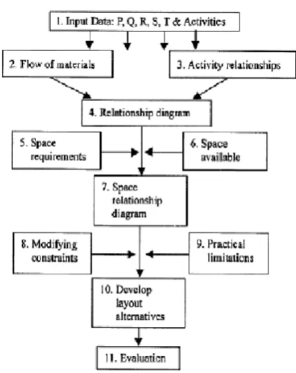
Systematic Layout Planning (SLP)
Further developed a layout procedure, named Systematic Layout Planning. The activity relationship chart is the basic input for the SLP method. Based on the input data & the relationship between activities, analysis of activity relationship and flow of material carried out and the relationship diagram develops. Then amount of space available and space required for every activity determines and a chart of space utilization constructs. From this space relationship diagram obtains. Then considering the practical limitations and modifications, several layouts develops. Then the most optimize layout gets selected and recommended for implementation (‘Facilities Planning’,
Book by James Tompkins), (Md. RiyadHossain et al., 2014).
After study and analysis of all the literature, it was found that digital manufacturing tool DELMIA is the most useful tool to provide solution in digitization of a manufacturing facility. And further reweaving different layout optimizations techniques and algorithm, to optimize the plant after the study on virtual layout developed in DELMIA, it was found that the systematic layout planning is the most efficient and suitable optimizations technique which can be applied for the given requirements. It is useful to optimize the space utilization and material flow cost & distance for enhancing production rate. Following flow chart shows the step involve for optimization in SLP technique,
Study of Industry & Data Collection
For three dimensional modeling, and optimizations of an industry, detail study of industry has to be done. So, layout of the industry and its dimensions, several department of that industry, their location, various kind of products produced, shop floor of industry, various machines, equipment and accessories present on the shop floor, their dimensions, processes carried out in manufacturing, material flow, assembly unit, R & D section, testing lab etc. was studied in detail.
Fig. 1. Steps of systematic layout planning
From this study it was found that, the industry deals with the designing and production of high performance instrumentation products. It is a provider to oil and gas industries, power plants and railway industries in India and abroad. Some of the products produced by industry are, double ferrule fittings, hydraulic fittings, floating ball valves, high pressure needle valves, instrumentation manifolds, tube and pipe clamps, SAE flanges, instrumentation hook-ups, condensate pots etc. set up of fluid controls has been situated in the area of 78.56 m x 38.50 m. Industry building is a three floor building and various departments are situated on these three floors to carry out all processes.
The actual space used as a shop floor area is 27.22 x 12.66 on each floor. In this area, manufacturing and other processes for all above mentioned components takes place. The activities like raw material storage, CNC machining, and primary inspection are carried out on ground floor. Special/craft machining, hydro-testing, valve assembly, and component storage is on the first floor and testing laboratory, fitting assembly, R&D department, final inspection and packaging takes place on the second floor. There are different types of machines and equipment like CNC machines, drilling machine, lathe machines, cutting machines, tapping mac
traube lathe machines and many more are used on the shop floor for the cutting, machining and manufacturing of the products. Accessories like assembly tables, chairs, stools computers, Xerox machine and workshop tables are also present on the shop floor. The actual set-up and location of the every machine and equipment on each shop floor was initially created as their foot prints using the 2 D CATIA drawing.
Data received from company,
Layout of the industry
Material flow distance and cost related data
31629 Bhushan Khartade et al. Improvisation of a facility layout u
Steps of systematic layout planning
From this study it was found that, the industry deals with the designing and production of high performance instrumentation oil and gas industries, power plants and railway industries in India and abroad. Some of the products produced by industry are, double ferrule fittings, ittings, floating ball valves, high pressure needle tube and pipe clamps, SAE ups, condensate pots etc. This set up of fluid controls has been situated in the area of 78.56 m try building is a three floor building and various departments are situated on these three floors to carry
The actual space used as a shop floor area is 27.22 x 12.66 on each floor. In this area, manufacturing and other processes for ll above mentioned components takes place. The activities like raw material storage, CNC machining, and primary inspection are carried out on ground floor. Special/craft testing, valve assembly, and component and testing laboratory, fitting assembly, R&D department, final inspection and packaging takes place on the second floor. There are different types of machines and equipment like CNC machines, drilling machine, lathe machines, cutting machines, tapping machines, grinders, traube lathe machines and many more are used on the shop floor for the cutting, machining and manufacturing of the products. Accessories like assembly tables, chairs, stools computers, Xerox machine and workshop tables are also up and location of the every machine and equipment on each shop floor was initially created as their foot prints using the 2 D CATIA drawing.
related data
Modeling of Shop Floor
After the above study and analysis, a three dimensional model of the shop floor were created by using a digital manufacturing software DELMIA. For modeling, study of the software and its command has been done, dimensio
accessories were measured. Then by modeling all these machines and accessories one by one, finally 3D models of all three floors have been created.
[image:4.595.322.551.191.307.2]Ground Floor 3-D Model
Fig 2. Snap shot of ground floor model
Model of ground floor represents all departments, machines and accessories present on the existing shop floor of the company.
First Floor 3-D Model
Fig 3. Snap shot of first floor model
Model of first floor represents all departments, machines and accessories present on the existing shop floor of the company.
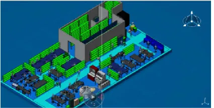
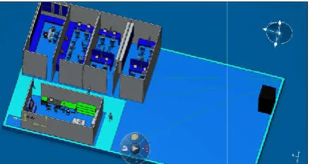
Second Floor 3-D Model
Fig. 4. Snap shot of second floor model
Improvisation of a facility layout using Delmia simulation and lean manufacturing technique
After the above study and analysis, a three dimensional model of the shop floor were created by using a digital manufacturing software DELMIA. For modeling, study of the software and its command has been done, dimensions of all machines and accessories were measured. Then by modeling all these machines and accessories one by one, finally 3D models of all three floors have been created.
Snap shot of ground floor model
floor represents all departments, machines and accessories present on the existing shop floor of the
Snap shot of first floor model
Model of first floor represents all departments, machines and t on the existing shop floor of the company.
Snap shot of second floor model
[image:4.595.318.549.394.530.2] [image:4.595.318.552.606.740.2]Model of second floor represents all departments, machines and accessories present on the existing shop floor of the company. As we can see, by using the DELMIA tool we can create the exact model shop floor as existing shop floor of the company. Now because of these 3D models it became very easy to visualize every location, equipment and processes in the company. It also helped to analyze the changes in the layout without actual implementation and plan the optimized approach before starting of actual production.
Simulation of Shop Floor
Simulation has also been done of shop floors using the same tool DELMIA by which we became able to virtually observe and plan the movements and routes of workers, materials and processes done on shop floor. It gave the experience of observing the whole company and production process at the desk only and one could plan the approach without going o the actual shop floor. It again provided the ability to analyze the manufacturing facility and plan for the optimized production in minimum production cost.
Optimization of Shop Floor
Material flow analysis
In this, the flow of material and frequency of flow between the work-stations and equipment is analyzed. The chart provides the information regarding the flow direction and intensity of flow between the machines. The necessary input to prepare the chart of flow intensity are travelling route of pro production volume per unit time and the quantity of product to be transport. The products are categorized, based on their processing sequence and formed product families. Then the sequence number, material movement, name and number of product are noted down for each family. With this data, operations sequence, 3-D models and dimensioned drawing, the material travel distanceare calculated. From this, the flow route and the distance travel by the material are obtained.
Activity relationship analysis
In activity relationship analysis, the closeness between the departments and activities is indicated by the value A,E,I,O,U and the reasons for closeness is indicated by the code 1,2,3,4,5,6,7,8,9. Its representation is given in following tables,
The necessary data was gathered from shop floor workers and officers. In the activity relationship chart, all departments of company are listed and the relationship closeness among all those departments is represented.
31630 International Journal of Current Research,
Model of second floor represents all departments, machines and accessories present on the existing shop floor of the As we can see, by using the DELMIA tool we can create the exact model shop floor as existing shop floor of the company. Now because of these 3D models it became very easy to visualize every location, equipment and processes in o analyze the changes in the layout without actual implementation and plan the optimized approach before starting of actual production.
Simulation has also been done of shop floors using the same ble to virtually observe and plan the movements and routes of workers, materials and processes done on shop floor. It gave the experience of observing the whole company and production process at the desk only and one could plan the approach without going on the actual shop floor. It again provided the ability to analyze the manufacturing facility and plan for the optimized
of flow between the stations and equipment is analyzed. The chart provides the information regarding the flow direction and intensity of flow between the machines. The necessary input to prepare the chart of flow intensity are travelling route of product, production volume per unit time and the quantity of product to be transport. The products are categorized, based on their processing sequence and formed product families. Then the sequence number, material movement, name and number of ed down for each family. With this data, D models and dimensioned drawing, the material travel distanceare calculated. From this, the flow route and the distance travel by the material are obtained.
In activity relationship analysis, the closeness between the departments and activities is indicated by the value A,E,I,O,U and the reasons for closeness is indicated by the code Its representation is given in following tables,
The necessary data was gathered from shop floor workers and officers. In the activity relationship chart, all departments of company are listed and the relationship closeness among all
The reason for the closeness of depa
[image:5.595.312.557.425.599.2]chart. This chart is one of the inputs for the space relationship diagram.
Fig 5. Activity relationship chart
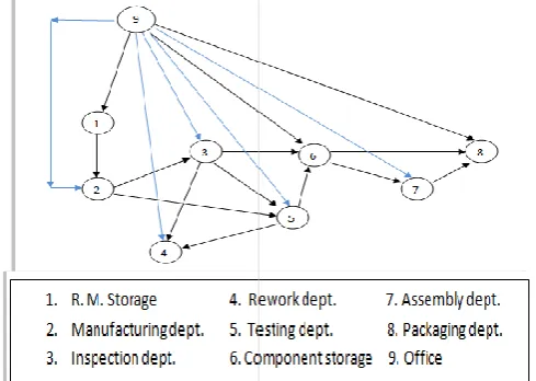
Relationship diagram indicates the relative positions and positional relationship of the equipment and machine considers the flow frequency and route of product and provides overall overview on material movement in the company. Relationship diagram is an input data for the formation of space relationship diagram.
Fig. 6. Relationship diagram
Space requirement and availability analysis
This step involves the study and analysis of the total floor space available in the industry and the total space required. It contains the space required for every machine, equipment and accessories such as work table
transformer etc. The space required for material storage, inspection, assembly and for office work is also measured. The space utilization is measured as the area of machine per unit area of floor. In this way the space requ
available space is calculated.
International Journal of Current Research, Vol. 08, Issue, 05, pp.31626-31633, May, 2016
The reason for the closeness of departments is also given in the chart. This chart is one of the inputs for the space relationship
Activity relationship chart
Relationship diagram indicates the relative positions and
positional relationship of the equipment and machines. It
considers the flow frequency and route of product and provides overall overview on material movement in the company. Relationship diagram is an input data for the formation of
Relationship diagram
requirement and availability analysis
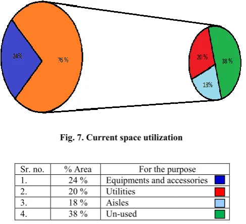
[image:5.595.50.281.591.699.2]As per the data made available by the company and study of industry, the existing available area of the shop floor of industry by adding all three floors area is 1032.1824 m
[image:6.595.42.286.151.372.2]this area, the utilized area of all three floors is 458.3931 m means the current space utilization of industry is 0.444 m of available area. Following pie chart shows the current distribution of area for various purposes in the company
Fig. 7. Current space utilization
Sr. no. % Area For the purpose 1. 24 % Equipments and accessories
2. 20 % Utilities
3. 18 % Aisles
4. 38 % Un-used
Table 1. Current space utilization
As we can see, only 24% of floor space is used for the equipment and accessories. Out of 76 % area, 20 % of area is used for the utilities and 18 % area is used for aisle. But industry is not using its remaining 38 % of area due to inappropriate layout arrangement.
Solution
After the above analysis of 3-D models of shop floor and analysis of several parameters related to facility layout for optimization solution is derived following various stapes as explained below,
Fig. 8. Space relationship diagram
31631 Bhushan Khartade et al. Improvisation of a facility layout using Delmia simulation and lean manufacturing technique
As per the data made available by the company and study of industry, the existing available area of the shop floor of
industry by adding all three floors area is 1032.1824 m2. Out of
all three floors is 458.3931 m2. It
means the current space utilization of industry is 0.444 m2/m2
of available area. Following pie chart shows the current distribution of area for various purposes in the company.
Current space utilization
For the purpose Equipments and accessories
Current space utilization
As we can see, only 24% of floor space is used for the equipment and accessories. Out of 76 % area, 20 % of area is used for the utilities and 18 % area is used for aisle. But industry is not using its remaining 38 % of area due to
D models of shop floor and analysis of several parameters related to facility layout for optimization solution is derived following various stapes as
diagram
Space relationship diagram
Space relationship diagram is an initial level layout which shows the positions of each department, area occupied and dimensions of each department and relation between them. Space data and the activity relationship
create this diagram. This diagram is proposed to find the promising locations of departments on the shop floor. Space constrained and closeness value in departments is also considered while generation of it.
Practical limitations and alternate layouts
The practical limitations were gathered from the shop floor workers and office employees. Considering all above analysis, models of new alternate layouts of shop floor are generated on the iteration basis. The limitations in design of sho
previous iteration are overcome in the next iteration. In this way by performing ten to twelve iterations alternate layouts are generated. Here only five iterations are presented.
Layout generation
Iteration 1
The analysis of three dimensional simulated model and space relationship diagram is used to generate the layouts at starting. After the generation of initial layouts, these were cross checked with the shop floor limitations and expected results. There were three measure concern
layouts. One of the major issues was improper utilization of ground floor space. This problem is addressed by relocation of rework department and proper arrangement of some machines. Another issue was material had to travel more di
rework and this is solved due to relocation of rework department. The third problem with initial layout was improper utilization of space on first and second floor. This is solved by rearrangement and relocation of equipment and accessories.
Iteration 2
Iteration 2 layouts are designed by eliminating the limitations of iteration 1 layouts. Initially, iteration 1 layout was with four limitations. First one was, because of the shifting of rework department to ground floor it lead to upsetting th
of material and operators. This issue is sorted out by relocating the positions and orientations of equipment. Second problem was again the under utilization of ground floor space. Now by shifting the ferrule inspection to ground floor, space ut
is improved. Third issue was the material had to travel to second floor for fittings assembly, so fitting assembly area is
shifted to 1st floor. Last issue was the empty space generated
because of shifting of rework and ferrule inspection area. T space is utilized for the assembly purpose of valve and fittings.
Iteration 3
Limitations of layout 2 are addressed and design of layout 3 is generated. Three major problems were noticed in that. First problem was adjustment of space for the fitting
on 1st floor.
Improvisation of a facility layout using Delmia simulation and lean manufacturing technique
Space relationship diagram is an initial level layout which shows the positions of each department, area occupied and dimensions of each department and relation between them. Space data and the activity relationship diagram are used to create this diagram. This diagram is proposed to find the promising locations of departments on the shop floor. Space constrained and closeness value in departments is also considered while generation of it.
lternate layouts
The practical limitations were gathered from the shop floor workers and office employees. Considering all above analysis, models of new alternate layouts of shop floor are generated on the iteration basis. The limitations in design of shop floor from previous iteration are overcome in the next iteration. In this way by performing ten to twelve iterations alternate layouts are generated. Here only five iterations are presented.
dimensional simulated model and space relationship diagram is used to generate the layouts at starting. After the generation of initial layouts, these were cross checked with the shop floor limitations and expected results. There were three measure concern recognized with initial layouts. One of the major issues was improper utilization of ground floor space. This problem is addressed by relocation of rework department and proper arrangement of some machines. Another issue was material had to travel more distance for rework and this is solved due to relocation of rework The third problem with initial layout was improper utilization of space on first and second floor. This is solved by rearrangement and relocation of equipment and accessories.
Iteration 2 layouts are designed by eliminating the limitations of iteration 1 layouts. Initially, iteration 1 layout was with four limitations. First one was, because of the shifting of rework department to ground floor it lead to upsetting the movement of material and operators. This issue is sorted out by relocating the positions and orientations of equipment. Second problem was again the under utilization of ground floor space. Now by shifting the ferrule inspection to ground floor, space utilization is improved. Third issue was the material had to travel to second floor for fittings assembly, so fitting assembly area is floor. Last issue was the empty space generated because of shifting of rework and ferrule inspection area. This space is utilized for the assembly purpose of valve and fittings.
Limitations of layout 2 are addressed and design of layout 3 is generated. Three major problems were noticed in that. First problem was adjustment of space for the fitting assembly area
[image:6.595.55.277.555.733.2]It is best addressed by the properly positioning and orienting the assembly tables and equipment. Second problem was the orientation and location of hydro testing machines. It is eliminated by relocation and changing the orientation of these
machines. And the 3rd problem was space available for the
packaging area was less. But because of relocation of hydro testing machines, the free space is added to packaging area which is enough for it.
Iteration 4
It was again observed that iteration 3 layouts also with 2 problems. One, the material flow distance from raw material store to machining area was unnecessarily more. It is addressed by directly giving a gate in the wall joining these two areas. Second, same as first one, the material flow distance between goods store and assembly was more. This is sorted out by providing a gate to store department which directly connect it to assembly area.
Iteration 5
One problem again observed in the iteration 4 layouts. The problem was related to space and directions for th
problem is solved by some rearrangement in positions and orientation of the machines and equipments. Fig. 9, Fig. 10, and Fig. 11 represents the ground floor, first floor and second floor layout models obtained after last iteration. These la satisfy all limitations and provide optimization of the company shop floors. By evaluating these layouts, different deliverables are calculated.
Evaluation
Layout evaluation involves the assessment of the parameters as space utilization, material flow distance, material flow cost and space saved for future expansion. It validates the results with the projected results.
Space utilization calculations
The space utilization is calculated for optimized layout and compared with existing one. The space utilization of new
optimized layout is 0.4851m2/m2 and existing layout is
0.4282m2/m2. So the percent improvement in space utilization
achieved is 13.29%.
Material flow distance calculations
The material travelling distance is calculated for the existing layout and new layout from raw material storage to the dispatch of that material. It is 162.181 km/month for existing layout and for the new layout, it is 110.091 km/month. Immense improvement in the material travel distance from floor to floor is seen due to the change in layout. The total material flow distance saved is 52.09 km/month. This results in saving of overall cost & time and improvement in productivity.
Material flow cost calculations
The material flow distance was a key input to calculate the material flow cost. Material travelling and handling in company is carried out by workers, small trolleys and lifts from machine to machine and floor to floor.
31632 International Journal of Current Research,
best addressed by the properly positioning and orienting the assembly tables and equipment. Second problem was the orientation and location of hydro testing machines. It is eliminated by relocation and changing the orientation of these problem was space available for the packaging area was less. But because of relocation of hydro testing machines, the free space is added to packaging area
It was again observed that iteration 3 layouts also with 2 problems. One, the material flow distance from raw material store to machining area was unnecessarily more. It is addressed by directly giving a gate in the wall joining these two areas. Second, same as first one, the material flow distance between store and assembly was more. This is sorted out by providing a gate to store department which directly connect it
One problem again observed in the iteration 4 layouts. The problem was related to space and directions for the aisles. This problem is solved by some rearrangement in positions and orientation of the machines and equipments. Fig. 9, Fig. 10, and Fig. 11 represents the ground floor, first floor and second floor layout models obtained after last iteration. These layouts satisfy all limitations and provide optimization of the company shop floors. By evaluating these layouts, different deliverables
Layout evaluation involves the assessment of the parameters as flow distance, material flow cost and space saved for future expansion. It validates the results with
The space utilization is calculated for optimized layout and space utilization of new and existing layout is . So the percent improvement in space utilization
The material travelling distance is calculated for the existing layout and new layout from raw material storage to the dispatch of that material. It is 162.181 km/month for existing layout and for the new layout, it is 110.091 km/month. in the material travel distance from floor to floor is seen due to the change in layout. The total material flow distance saved is 52.09 km/month. This results in saving of overall cost & time and improvement in productivity.
The material flow distance was a key input to calculate the material flow cost. Material travelling and handling in company is carried out by workers, small trolleys and lifts
So the total cost of material flow through all above mediums for existing layout is INR 21.043/ trip of material and cost for the new layout is INR 11.499/ trip. Hence by using new layout INR 1,34,451 per annum will be saved.
Space for future expansion calculations
Devoted space for future set up of company is one of the important out-come of this project. Due to the rearrangement of departments and proper space utilization in the new layout of shop floor, space is saved on shop floor. The unused space on ground floor and first floor is utilized and hence the empty space on second floor got available for the future expansion. In current layout there is no space available for the future expansion but in the new layout 143.3083 m
available for future expansion of facili improvement achieved is 143.3083 m
Modeling and Simulation of New Shop Floor Layouts
The new optimized layout of shop floors is created by following the above mentioned procedure. The optimizations in terms of space utilization, material
flow cost and space for future expansion is accomplished and the desired results are achieved. Now again the three dimensional simulated model of all three floors is created by using digital manufacturing tool DELMIA to virtually experience and evaluate the new layout of shop floors. It helped to understand how the new optimized shop floor layout will be. By observing and analyzing these models one becomes able to visualize the position of all departments, machines, equipments and aisles before actual implementation of new layout. It also facilitated to make some minor changes in the layout after observation. In this way, these digital three dimensional models creating impact in the generation and optimization of the layout of shop f
[image:7.595.327.540.483.597.2]New ground floor model
Fig. 9. Snap shot of new ground floor model
New first floor model
Fig 10. Snap shot of new first floor model
International Journal of Current Research, Vol. 08, Issue, 05, pp.31626-31633, May, 2016
flow through all above mediums for existing layout is INR 21.043/ trip of material and cost for the new layout is INR 11.499/ trip. Hence by using new layout INR 1,34,451 per annum will be saved.
Space for future expansion calculations
or future set up of company is one of the come of this project. Due to the rearrangement of departments and proper space utilization in the new layout of shop floor, space is saved on shop floor. The unused space or is utilized and hence the empty space on second floor got available for the future expansion. In current layout there is no space available for the future
expansion but in the new layout 143.3083 m2 space will be
available for future expansion of facility. Hence the
improvement achieved is 143.3083 m2.
Modeling and Simulation of New Shop Floor Layouts
The new optimized layout of shop floors is created by following the above mentioned procedure. The optimizations in terms of space utilization, material flow distance, material flow cost and space for future expansion is accomplished and the desired results are achieved. Now again the three dimensional simulated model of all three floors is created by using digital manufacturing tool DELMIA to virtually xperience and evaluate the new layout of shop floors. It helped to understand how the new optimized shop floor layout will be. By observing and analyzing these models one becomes able to visualize the position of all departments, machines, isles before actual implementation of new layout. It also facilitated to make some minor changes in the layout after observation. In this way, these digital three dimensional models creating impact in the generation and optimization of the layout of shop floors.
Snap shot of new ground floor model
[image:7.595.329.542.637.744.2]New second floor model
Fig. 11. Snap shot of new second floor model
RESULTS AND DISCUSSION
By implementing the optimized shop floor layout the space utilization of industry gets enhanced from 0.4851
0.4282 m2/m2, material flow distance is reduced from 162.181
km/month to 110.091 km/month, material flow cost minimizes from INR 21.043/ trip to INR 11.499/ trip and 143.3083 m space is obtained as available for future expansion. Also the company got the virtual models of its shop floors which can be useful for the company in future for analyzing the company performance.Hence using digital manufac
technique for optimizations the intended optimization is achieved in new shop floor layout of company. Due to these results company production rate and overall profit will be increased.
Conclusions
From all above mentioned study and obtained results, we can say that Digital manufacturing is the technology, by which companies can manage manufacturing data, optimizes production processes, machine utilization and increases collaboration between engineers of different departments. Also DELMIA makes user able to virtually experience
factory production before the actual production starts and plays vital role in planning optimized approach.
planning technique is very useful to optimize the plant and process parameter by eliminating non value added activities as presented in this paper. This work done by interrogating digital manufacturing and lean manufacturing technique has successfully added the value and optimized the required parameter for the company.
31633 Bhushan Khartade et al. Improvisation of a facility layout using
Snap shot of new second floor model
the optimized shop floor layout the space
utilization of industry gets enhanced from 0.4851 m2/m2 to
, material flow distance is reduced from 162.181 km/month to 110.091 km/month, material flow cost minimizes
11.499/ trip and 143.3083 m2 of
space is obtained as available for future expansion. Also the company got the virtual models of its shop floors which can be useful for the company in future for analyzing the company Hence using digital manufacturing and lean technique for optimizations the intended optimization is achieved in new shop floor layout of company. Due to these results company production rate and overall profit will be
ned results, we can is the technology, by which companies can manage manufacturing data, optimizes production processes, machine utilization and increases collaboration between engineers of different departments. Also virtually experience their entire factory production before the actual production starts and plays vital role in planning optimized approach. Systematic layout is very useful to optimize the plant and by eliminating non value added activities as presented in this paper. This work done by interrogating digital manufacturing and lean manufacturing technique has successfully added the value and optimized the required
The company is exhibiting its capabilities as a lean organization to its customers. The optimized shop floor layouts offer secure and pleasant surroundings to employees which definitely added to improvement of employee confidence and scientific planning flavor to the working environment.
REFERENCES
Alex, S., Lokesh, A.C., Ravikumar,
utilization improvement in cnc machining unit through lean
layout’, SASTECH Journal, Volume 9, Issue 2, September.
Elena-Iuliana Gingu and Prof. dr. eng. Miron Zapciu, ‘Improving layout and workload of manufacturing System using Delmia Quest simulation and inventory approach’, International Journal of Innovative Research in Advanced
Engineering, ISSN:2349-2163,Volume 1
2014
http://www.3ds.com/productsservice/delmia/capabilities/ digital-manufacturing
‘Facilities Planning’, Book by James Tompkins Chryssolouris, G., Mavrikios, D
Michalos, G. and Georgoulias,’
Manufacturing history, perspectives, and outlook’, Proc. IMechE ,Vol.223 Part B: J. Engineering Manufacture, JEM1241, 20 June,pg.
451-http://www.3ds.com/fileadmin/PRODUCTS/DELMI A/ PDF/Brochures/delmia
Jiaqin Yang and Richard H. Deane, ‘
Manufacturing Cell Formation Design’,
Manufacturing Systems, Vol. 5,Issue 4/5, pp.87 Hari Prasad, N., Rajyalakshmi
2014. ‘A Typical Manufacturing Plant Layout Desi Using CRAFT Algorithm’, Procedia Engineering, volume 97, page: 1808 – 1814
Md. RiyadHossain, Md. KamruzzamanRasel,
SubrataTalapatra, ‘Increasing Productivity through Facility LayoutImprovement using Systematic Layout Planning Pattern Theory’, Global Jou
Engineering, Volume 14 Issue 7 Version 1.0 Year 2014 Noor Azlina Mohd. Salleh, Salmiah Kasolang, Ahmed Jaffar,
‘Simulation of Integrated Total Quality Management (TQM) with Lean Manufacturing (LM) Practices in Forming Process Using De
Engineering 41, pg.1702–1707, 2012 Karthik, T. and Senthilkumar
ofproductivity through layout optimisation in pump
industry’, International Journal
3, Issue 2, December.
*******
Improvisation of a facility layout using Delmia simulation and lean manufacturing technique
The company is exhibiting its capabilities as a lean organization to its customers. The optimized shop floor layouts offer secure and pleasant surroundings to employees which definitely added to improvement of employee fic planning flavor to the working
Ravikumar, N. 2010. ‘Space utilization improvement in cnc machining unit through lean
, Volume 9, Issue 2, September. Iuliana Gingu and Prof. dr. eng. Miron Zapciu, ‘Improving layout and workload of manufacturing System using Delmia Quest simulation and inventory approach’, International Journal of Innovative Research in Advanced 2163,Volume 1, Issue 6, July
http://www.3ds.com/productsservice/delmia/capabilities/
‘Facilities Planning’, Book by James Tompkins
D., Papakostas, N., Mourtzis, D., and Georgoulias,’ K. 2008. Digital Manufacturing history, perspectives, and outlook’, Proc. IMechE ,Vol.223 Part B: J. Engineering Manufacture,
-460.
http://www.3ds.com/fileadmin/PRODUCTS/DELMI A/ PDF/Brochures/delmia-dpm-assembly.pdf
d Richard H. Deane, ‘Strategic Implication of
Manufacturing Cell Formation Design’,Integrated
Manufacturing Systems, Vol. 5,Issue 4/5, pp.87-96,1994. , Rajyalakshmi, G., Sreenivasulu Reddy, A. ‘A Typical Manufacturing Plant Layout Design Using CRAFT Algorithm’, Procedia Engineering, volume
Md. RiyadHossain, Md. KamruzzamanRasel,
SubrataTalapatra, ‘Increasing Productivity through Facility LayoutImprovement using Systematic Layout Planning Pattern Theory’, Global Journal of Researches in Engineering, Volume 14 Issue 7 Version 1.0 Year 2014 Noor Azlina Mohd. Salleh, Salmiah Kasolang, Ahmed Jaffar,
‘Simulation of Integrated Total Quality Management (TQM) with Lean Manufacturing (LM) Practices in Forming Process Using Delmia Quest’, Procedia
1707, 2012
Senthilkumar, M. 2012. ‘Improvisation ofproductivity through layout optimisation in pump
Journal of Lean Thinking, Volume