ISSN Online: 2160-889X ISSN Print: 2160-8881
DOI: 10.4236/opj.2018.88023 Aug. 27, 2018 277 Optics and Photonics Journal
Performance Analysis of ASK and PSK
Modulation Based FSO System Using
Coupler-Based Delay Line Filter under Various
Weather Conditions
Mohd Ashraf, Gaurav Baranwal, Dinesh Prasad, Saima Idris, Mirza Tariq Beg
Department of Electronics and Communication, F/O Engineering and Technology, Jamia Millia Islamia, Delhi, India
Abstract
Free space optical communication (FSO) proves to be very effective and effi-cient technology for wireless communication. This work basically deals with the designing of FSO systems. Further, a comparative study has been made to ascertain which modulation technique proves better for communication. This paper investigates the performance of ASK and PSK modulation based FSO system by varying different FSO parameters under several conditions includ-ing haze, rain, mist and fog. Finally, simulation results are analysed and dis-cussed.
Keywords
FSO, Bit Error Rate (BER), Amplitude Shift Keying (ASK), Phase Shift Keying (PSK), Attenuation
1. Introduction
Nowadays, a very high-quality service demand for multimedia services is in-creasing drastically. Optical fibres have been used for so many years to fulfil this demand. But the shortcoming of these fibres is that it is not suitable for remote areas deployment and enhances the cost of the system. So, an alternative ap-proach to meet the desired requirements is free space optics (FSO) technology. FSO uses optical wireless links to offer point to point communication in outdoor terrestrial regions with clear line of sight (LOS). FSO system has an optical transceiver unit which has a bi-directional functionality. Each unit involves an
How to cite this paper: Ashraf, M., Baranwal, G., Prasad, D., Idris, S. and Beg, M.T. (2018) Performance Analysis of ASK and PSK Modulation Based FSO System Using Coupler-Based Delay Line Filter under Various Weather Conditions. Optics and Photonics Journal, 8, 277-287. https://doi.org/10.4236/opj.2018.88023
Received: July 18, 2018 Accepted: August 24, 2018 Published: August 27, 2018
Copyright © 2018 by authors and Scientific Research Publishing Inc. This work is licensed under the Creative Commons Attribution International License (CC BY 4.0).
DOI: 10.4236/opj.2018.88023 278 Optics and Photonics Journal
optical source, telescope which transmits light through free space, which behaves as a communication channel in it, to another telescope and receives the informa-tion [1].
Advantages of FSO include high reuse factor, robustness, easily deployable, li-cense free band, no signal interference. FSO system is used for various applica-tions, such as in LAN networks for campus connectivity with Gigabyte Ethernet speeds, in metropolitan area network, spacecraft communication, video surveil-lance, back-haul for cellular networks like 5G etc. [2].
Unfortunately, FSO links are prone to inhomogeneities produced by the tem-perature and pressure in the atmosphere. This causes atmospheric turbulence effect. This results fluctuations in the received signal, called as scintillation effect or turbulence-induced fading. This is analogous to fading in RF system. Due to this, FSO suffers with the drawback of less reliable link connectivity mainly for distances more than 1000 metre and is sensitive to various weather conditions [3] [4] [5].
2. System Architecture
2.1. ASK Modulation Technique
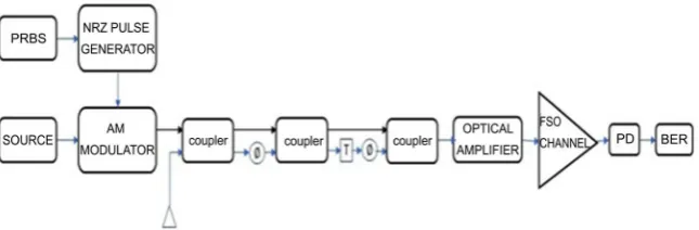
The block diagram of the proposed FSO system using ASK modulation tech-nique is shown in Figure 1. It can be divided into 4 stages. First stage is trans-mitter which contains an optical source, bit sequence generator, pulse generator and AM modulator. Here pulse generator encodes the digital data of bit se-quence generator and its output modulated the carrier signal of optical source using amplitude modulator. Second stage is delay line filter. It is utilised to compensate the dispersion effects which, in turn, reduces the effects caused by atmospheric turbulence, fading etc. the coupling coefficients of the coupler pre-sent in this filter can change the dispersion slope. Hence, dispersion and disper-sion slope value of the filter can be designed accordingly [6] [7]. The third stage is FSO channel as described earlier. The final stage is the receiver where the op-tical detector detects the signal and converts it into the electrical signal.
2.2. PSK Modulation Technique
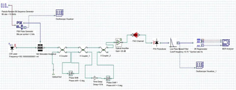
[image:2.595.214.537.598.704.2]The block diagram of the proposed FSO system using PSK modulation tech-nique is shown in Figure 2. It consists of 4 stages. First stage is transmitter stage.
DOI: 10.4236/opj.2018.88023 279 Optics and Photonics Journal
Figure 2. Block diagram of the proposed PSK modulated FSO system.
In this PSK pulse generator encodes the digital data of bit sequence generator. Encoded data modulates the optical carrier signal using phase modulator. Sec-ond stage is delay line filter used to compensate dispersion effects and reduce the turbulence and fading caused by it. The stage is FSO channel where atmosphere acts as the channel. Fourth stage is the receiver stage for the detection of the op-tical signal and converting it into an electrical signal.
3. Simulation Setup
3.1. ASK Modulated FSO Design Simulation
A design of ASK modulation FSO system was simulated and modelled for per-formance analysis under various weather condition using OptiSystem software shown in Figure 3. The optical transmitter consists of Pseudo-Random Binary Sequence (PRBS) generator representing data bits of bit rate 10Gbits/sec. The output of this is encoded with Non-Return to Zero (NRZ) pulse generator. A continuous wave laser of 60 dBm and wavelength 1550 nm is modulated by the encoded bits using optical amplitude modulator. The output of the modulator is the optical signal which is fed into the delay line filter using x-couplers. The first coupler decomposes the input signal into two, depending on the coupling coeffi-cient. One of the split signals is phase shifted and the other one is kept as it is. Then they are recombined at the second coupler. These are again split and time delayed and phase shifted. Finally, at the third coupler, they are combined to re-ceive the compensated signal. The free space optics medium (FSO channel) with different range and attenuations has been considered and analysed. The optical receiver consists of PIN photodiode and a 3R-regenerator. The PIN photodiode converts received optical signal into the corresponding electrical signal [8]. The 3R-regenerator obta in the original bit sequence. The oscilloscope visualizers and bit error rate (BER) analyzer are used to analyse the results obtained.
3.2. PSK Modulated FSO Design Simulation
DOI: 10.4236/opj.2018.88023 280 Optics and Photonics Journal
Figure 3. Simulation structure for ASK modulated FSO system.
Figure 4. Simulation structure for PSK modulated FSK system.
carrier signal output of PSK pulse generator modulates the optical carrier signal phase resulting in the PSK modulated signal. Modulated signal is passed through the delay line filter to improve the performance of the FSO system as explained earlier. Compensated signal is passed through the FSO channel. The perform-ance is analysed by taking different ranges and attenuation values of the FSO channel corresponding to different weather conditions. The optical receiver has PIN photodiode and a 3R-regenerator to obtained original bit sequence in elec-trical signal form. Finally, the performance is analysed with the help of oscillo-scope visualizers and BER analyzer.
3.3. FSO System Parameters under Various Atmospheric
Conditions
[image:4.595.60.541.297.480.2]DOI: 10.4236/opj.2018.88023 281 Optics and Photonics Journal
[image:5.595.210.538.163.254.2]and given the maximum visibility range and attenuation present for such weather conditions. Table 1 contain FSO system parameters under various con-ditions. Free space optical system parameters for various weather conditions like haze, rain-mist, snow and medium Fog are included in Tables 2-5 respectively.
Table 1. Free space optical system parameters under various atmospheric conditions.
ATMOSPHERIC CONDITION ATTENUATION (dB/km)
HAZE 10.94 - 20.68
Rain 6.0 - 30
Mist 28.56 - 31.45
Snow 40
[image:5.595.211.540.286.383.2]Mid-Fog 70
Table 2. Result analysis for Haze condition.
Work Attenuation (dB/km) LOS (metre) Q-factor BER Bit Rate (Gbps)
Ref [11] (ASK) 20 100 m 3.86 5.03e−005 10
Ref [12] 20 800 m 21.08 - 2.5
Ref [13] 20 500 m 45.96 0 10
ASK DLF (proposed) 20 3500 m 56.5069 0 10
[image:5.595.211.539.420.503.2]PSK DLF (proposed) 20 3500 m 57.0486 0 10
Table 3. Result analysis for rain and mist condition.
Work Attenuation (dB/km) LOS (metre) Q-factor BER Bit Rate (Gbps)
Ref [11] (ASK) 30 100 3.86079 5.025e−005 2.5
Ref [12] 30 800 9.62 - 2.5
ASK DLF (proposed) 30 2500 31.4472 2.292e−217 10
PSK DLF (proposed) 30 2500 34.0397 2.855e−254 10
Table 4. Result analysis for snow condition.
Work Attenuation (dB/km) LOS (metre) Q-factor BER Bit Rate (Gbps)
Ref [14] 40 - 30.2722 9.174e−202 2.5
ASK DLF (proposed) 40 1900 44.994 0 10
PSK DLF (proposed) 40 1900 46.139 0 10
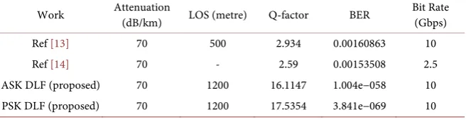
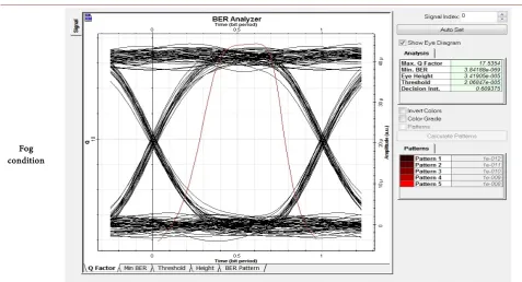
Table 5. Result analysis for medium Fog condition.
Work Attenuation (dB/km) LOS (metre) Q-factor BER Bit Rate (Gbps)
Ref [13] 70 500 2.934 0.00160863 10
Ref [14] 70 - 2.59 0.00153508 2.5
ASK DLF (proposed) 70 1200 16.1147 1.004e−058 10
[image:5.595.210.540.536.606.2] [image:5.595.211.543.639.725.2]DOI: 10.4236/opj.2018.88023 282 Optics and Photonics Journal
Proposed ASK delay line filter and PSK delay line filter under haze condition have 3500 m line of sight compared to previous published work and having a high quality factor of 56.5069 and 57.0486 respectively.
Proposed ASK delay line filter and PSK delay line filter under rain and mist condition have 2500 m line of sight compared to previous published work and having a high quality factor of 31.4472 and 34.0397 respectively.
Proposed ASK delay line filter and PSK delay line filter under snow condition have 1900 m line of sight compared to previous published work and having a high quality factor of 44.994 and 46.139 respectively.
Proposed ASK delay line filter and PSK delay line filter under haze condition have 1200 m line of sight compared to previous published work and having a high quality factor of 16.1147 and 17.5354 respectively.
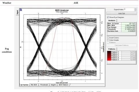
Eye diagram for various weather conditions of ASK DLF and PSK DLF is mentioned in Table 6 that include maximum quality factor, minimum BER and threshold.
4. Conclusion
A new approach for performance analysis of ASK and PSK modulation based FSO system using coupler-based Delay Line Filter under various weather conditions
Table 6. Eye diagram for various weather conditions.
Weather ASK
[image:6.595.59.541.389.708.2]Fog condition
DOI: 10.4236/opj.2018.88023 283 Optics and Photonics Journal Continued
[image:7.595.74.542.86.371.2]Haze condition
Figure 6. 10Gbps BER ASK DLF_3.5 KM_20 dB/km.
[image:7.595.60.546.97.707.2]Rain and Mist condition
DOI: 10.4236/opj.2018.88023 284 Optics and Photonics Journal Continued
[image:8.595.63.540.85.392.2]Snow condition
Figure 8. ASK DLF_1.9 KM_40 dB/km 10 Gbps BER.
[image:8.595.57.552.94.696.2]Haze condition
DOI: 10.4236/opj.2018.88023 285 Optics and Photonics Journal Continued
Rain and Mist condition
Figure 10. PSK DLF_2.5 KM_30 dB/km 10 Gbps BER.
[image:9.595.57.538.82.712.2]Snow condition
DOI: 10.4236/opj.2018.88023 286 Optics and Photonics Journal Continued
[image:10.595.59.537.83.341.2]Fog condition
Figure 12. PSK DLF_1.2 KM_70 dB/km 10 Gbps BER.
has been presented having a feature of high Q-factor and BER is very close to zero.
Conflicts of Interest
The authors declare no conflicts of interest regarding the publication of this pa-per.
References
[1] Khalighi, M.A. and Uysal, M. (2014) Survey on Free Space Optical Communication: A Communication Theory Perspective. IEEE Communications Surveys & Tutorials, 16, 2231-2258. https://doi.org/10.1109/COMST.2014.2329501
[2] Alzenad, M., Shakir, M.Z., Yanikomeroglu, H. and Alouini, M.S. (2018) FSO-Based Vertical Backhaul/Fronthaul Framework for 5G+ Wireless Networks. IEEE Com-munications Magazine, 56, 218-224. https://doi.org/10.1109/MCOM.2017.1600735 [3] Varotsos, G.K., Stassinakis, A.N., Nistazakis, H.E., Tsigopoulos, A.D., Peppas, K.P., Aidinis, C.J. and Tombras, G.S. (2014) Probability of Fade Estimation for FSO Links with Time Dispersion and Turbulence Modeled with the Gamma-Gamma or the I-K Distribution. Optik-International Journal of Light and Electron Optics, 125, 7191-7197. https://doi.org/10.1016/j.ijleo.2014.08.047
[4] Zhu, X.M. and Kahn, J.M. (2002) Free-Space Optical Communication through At-mospheric Turbulence Channels. IEEE Transactions on Communications, 50, 1293-1300. https://doi.org/10.1109/TCOMM.2002.800829
DOI: 10.4236/opj.2018.88023 287 Optics and Photonics Journal
https://doi.org/10.1109/JPHOT.2015.2470106
[6] Duthel, T., et al. (2006) Quasi-Analytic Synthesis of Nonrecursive Optical Delay Line Filters for Reliable Compensation of Dispersion Effects. Journal of Lightwave Technology, 24, 4403-4410. https://doi.org/10.1109/JLT.2006.881477
[7] Rahim, A., et al. (2012) Finite Impulse Response Filter Using 4-Port MMI Couplers for Residual Dispersion Compensation. Journal of Lightwave Technology, 30, 990-996. https://doi.org/10.1109/JLT.2012.2185038
[8] Ashraf, M. and Ranjan, R. (2018) Tunable Single Passband Microwave Photonic Filter Based on Direct Generation Technique. 3rd International Conference on Mi-crowave and Photonics (ICMAP), Dhanbad, 9-11 February 2018, 1-2.
https://doi.org/10.1109/ICMAP.2018.8354521
[9] Vavoulas, A., Sandalidis, H.G. and Varoutas, D. (2012) Weather Effects on FSO Network Connectivity. IEEE/OSA Journal of Optical Communications and Net-working, 4, 734-740.https://doi.org/10.1364/JOCN.4.000734
[10] Nebuloni, R. and Capsoni, C. (2016) Effects of Adverse Weather on Free Space Op-tics. In: Uysal, M., et al., Eds., Optical Wireless Communications, Signals and Communication Technology, Springer International Publishing, Switzerland, 47-68. [11] Das, S. and Chakraborty, M. (2016) ASK and PPM Modulation Based FSO System under Varying Weather Conditions. 2016 IEEE 7th Annual Ubiquitous Computing, Electronics & Mobile Communication Conference (UEMCON), New York, NY, 1-7. https://doi.org/10.1109/UEMCON.2016.7777825
[12] Kadhim, Dr.S.A., Shakir, A.A.J., Mohammad, Dr.A.N. and Mohammad, N.F. (2015) System Design and Simulation Using (OptiSystem7.0) for Performance Characteri-zation of the Free Space Optical Communication System. International Journal of Innovative Research in Science, Engineering and Technology, 4, No. 6.
[13] Jain, D. and Mehra, R. (2017) Performance Analysis of Free Space Optical Commu-nication System for S, C and L Band. International Conference on Computer, Communications and Electronics (Comptelix), Jaipur, 1-2 July 2017, 183-189. [14] Shaina and Gupta, A. (2016) Comparative Analysis of Free Space Optical