Bidirectional Partial Power Converter Interface for
Energy Storage Systems to Provide Peak Shaving in
Grid-Tied PV Plants
Nicol´as M¨uller
1,2, Samir Kouro
1, Pericle Zanchetta
2and Patrick Wheeler
21 Departament of Electronic Engineering, Universidad T´ecnica Federico Santa Mar´ıa, Valpara´ıso, Chile
2 Department of Electrical and Electronic Engineering, University of Nottingham, Nottingham, United Kingdom
Email: [email protected]
Abstract—The ever growing participation of modern renew-able resources in electric markets has shaken the paradigm of generation-demand constant match. Most modern renewables add intermittent behaviour and high variability to electric mar-kets, forcing other renewables and themselves to perform power curtailment and/or having extra generating units connected to the network to compensate power, voltage and frequency variations. In order to handle this scenario, Energy Storage Systems (ESSs) have risen as enabling technologies capable to provide backup energy to compensate power, voltage and frequency fluctuations and, at the same time, offer additional benefits as ancillary services, peak shaving, load shifting, base load generation, etc. This paper presents a novel bidirectional Partial Power Converter (PPC), as an interface between a Battery ESS (BESS) and a grid-tied Photovoltaic (PV) plant. To obtain a better understanding of the converter, its mathematical model is presented and its operation modes are explained. The main purpose of this config-uration is to provide peak shaving capability to a grid-tied PV plant, while providing a high efficiency BESS. Simulation results show the operation of the full system (grid-tied PV plant and BESS), performing peak shaving under a step-down and up in solar irradiation.
I. INTRODUCTION
Wind and PV energy have been at the forefront of re-newables integration [1]. During the last decades electric markets have experience an immense growth in participation of (traditional and modern) renewable resources, where modern renewables have reached an impressive 10.2% [2]. This has been mostly motivated by government politics, environmental concerns and fossil fuel depletion [3].
High variability and intermittency of modern renewables have set a virtual limit to renewables participation share in electric markets, since highly variable systems require back-up energy generation [4]–[6]. Nowadays, the mainstream solution to deal with generation-demand mismatches is to have spinning-reserves [5], i.e. sets of back up fast-response costly fossil fuel based generating systems, which must be kept operating idle or at low power level.
ESSs have been vastly researched as an alternative to deal with generation-demand mismatch and provide additional services [6]–[10]. In [6], the addition of ESSs to Wind farms in order to perform peak shaving is analysed. Where an ESS sizing strategy based on Homogeneous Markov Chain, considering wind-storage reliability and increasing the income,
is proposed. In [7], the addition of BESS to perform peak shaving in a grid-tied network composed of several loads and PV generation is proposed. The sizing of the BESS considers different pricing strategies, probabilistic neural network fore-casting of the behaviour of the load and PV generation. In [8], [9], the addition of super capacitor based ESS is considered to perform global maximum power point tracking in a central inverter PV plant, while complying grid code restrictions on maximum power variation per minute. The addition of a BESS to an islanded wind-diesel-loads power sysatem is analysed in [10], where the BESS provides peak shaving and frequency regulation capabilities.
A paramount part of adding ESSs to a system is choosing the proper Energy Storage Device (ESD) for the application among several different technologies, namely Pumped Hydro Storage, Compressed Air Energy Storage, Flywheel, Fuel Cell, Rechargeable Batteries, Super Capacitor, etc. There have been some studies comparing ESDs features, for instance, in [11] price, energy density, power density, specific power, specific energy, discharge/charge rate, life cycle, depth of discharge, lifespan, energy conversion efficiency, daily self-discharge rate,and ramp time of several ESDs, to provide uninterruptible power supply to data centres, are presented. A deeper com-parison of ESDs is presented in [12], where several ESDs are numerically analysed presenting their specific energy, energy density, specific power, power density, efficiency, lifespan, life cycle, life cycle, daily self-discharge rate and scale, cost.
Efficiency is a topic of great importance when analysing power systems and even more when analysing ESDs, since its bidirectional power flow nature incurs in losses during both energy conversion processes (storing and releasing energy). In order to quantify those losses, table I summarises the energy conversion efficiency and daily self-discharge rate of several ESDs shown in [12].
TABLE I
ESDENERGY CONVERSION EFFICIENCY AND DAILY SELF-DISCHARGE [12]
ESS Efficiency Daily self-discharge Lead-acid 63−90% 0.033−1.10%
Lithium-ion 70−100% 0.03−0.33%
Super capacitor 65−99% 0.46−40%
Flywheel 70−96% 24−100%
Pumped Hydro. 65−87% 0%
Compressed Air. 57−89% 0%
power flow applications, such as PV power plants [13]–[15], long LED arrays [16] and electric vehicle fast charging stations [17].
This work proposes a novel bidirectional partial power converter topology, as an interface to connect a ESD to a grid-tied PV plant, in order to provide peak shaving capability. Lithium-ion batteries were chosen as the ESD to be applied, since they present the highest efficiency range and the lowest daily self-discharge rate (according to [12]).
This paper is organised as follows: section II presents the proposed configuration, its models, Partial Power Converters equations and BESS sizing. The control scheme for the system is described in section III, the simulation results are explained in section IV and finally section V provides the conclusions of the work.
II. CONFIGURATION&MATHEMATICAL MODELS
The proposed configuration is shown in Fig. 1, where a BESS is connected to the dc-link of a central inverter PV plant. The battery pack is interfaced, to the dc-link of the central inverter configuration, through5 interleaved PPCs. Each PPC is formed by8semiconductors (MOSFETs), a transformer and an inductance, connected as shown in the figure. The central inverter configuration is composed by an array of several PV modules and a single 2 Level Voltage Source Inverter (2LV SI) connected to the grid.
The mathematical model of PPC j (j = {1, . . . ,5}) is described by equations (1) to (6). The first 3 equations correspond to voltage dynamics, namely voltage across the inductance L (vLj), voltage across the top winding and its
semiconductors (vf bpj) and voltage in the bottom winding and
its semiconductors (vf bsj). The latter3 equations correspond
to the current dynamics of PPC j, where ixj, ibpj and ippcj
correspond respectively to the current through inductance L, the bypass current and partial power converter current.
The variables mj, vx and vpv represent respectively the
modulation index of PPC j (mj ∈ [0,1]), the voltage in the
terminals of the battery pack and the voltage across the dc-link. The parameters n1 and n2 correspond respectively to
the number of turns in the primary (Fig. 1, top winding) and secondary (Fig. 1, bottom winding) of the transformer.
vLj =
n
2 n1+n2
·vpv·mj−vx (1)
vf bpj =
n
1 n1+n2
·vpv·mj (2)
vf bsj =
n
2 n1+n2
·vpv·mj (3)
ixj =
1
s·L
n
2 n1+n2
·vpv·mj−vx
(4)
ibpj =
n
2 n1+n2
·mj·ixj (5)
ippcj =
n
1 n1+n2
·mj·ixj (6)
In order to increase the equivalent switching frequency and reduce the current ripple from and towards the battery pack and dc-link, 5 PPCs are interleaved and their PWM carriers are shifted inφ= 2π/n, wherenis the amount of interleaved PPCs (φ= 2π/5 in this case).
The mathematical model of the2LV SI grid currents indq
rotational reference frame (igd and igq), in Laplace domain,
is shown in equations (7) and (8). Where Lg, Rg, ω, vrd, vrq, vgd and vgq correspond respectively to the inductance
and resistance of the filter, grid angular frequency, inverter voltages indqrotational axes and grid voltages indqrotational reference frame.
igd=
1
Lg·s+Rg
(vrd+Lg·ω·igq−vgd) (7)
igq=
1
Lg·s+Rg
(vrq−Lg·ω·igd−vgq) (8)
The mathematical model of the voltage across the dc-link capacitorCpv (vpv) is shown in equation (9). Whereipv,ibp, mu,mv,mw,igu,igv,igw correspond to the PV plant output
current, total bypass current (through all PPCs), modulation indexes per inverter phase and grid currents.
vpv=
1
s·Cpv
(ipv+ibp−mu·igu−mv·igv−mw·igw)
(9)
A. Partial Power Converters
In order for a power converter to be considered a PPC, the power processed by the converter must be lower than the input power. This relationship is called partial power ratio (kpr) and
is mathematically represented by the ratio between the PPC processed power and its input power [16]. Therefore, a power converter must comply with kpr < 1 to be a PPC. Table
Fig. 1. Proposed configuration
TABLE II PARTIALITY EQUATIONS
Power flow towards BESS Power flow towards dc-link
kpr bess=
vx·ippc
vpv·ibp
kpr dc=
vpv·ibp
vx·ippc
Gv bess=
vx
vpv
Gv dc=
vpv
vx
ηbess=Gv bess+kpr bess ηdc=
Gv dc·kpr dc
Gv dc+kpr dc
towards the BESS (noted by bess) and towards the dc-link
(noted by dc).
WhereGvandηcorrespond respectively to the voltage gain
and the efficiency of the converter.
B. Battery Energy Storage Sizing
A worst case scenario of providing 10% of the PV plant peak power (10%of 1M W) duringt= 10minutes was con-sidered. This time consideration corresponds to the available time for non-spinning reserves to respond after a contingency, having to be fully operational and able to provide 100% of its rated power to the electric network [18]. Hence, the BESS must be able to provide:
EBESS =
10%·Ppv mpp
1000·60 ·t[kW h] = 17[kW h] (10)
Where Ppv mpp is the maximum power the PV plant can
generate and tis the time in minutes.
Due to computational limitations the peak shaving effect provided by the BESS is analysed during short time intervals, nevertheless the battery pack was designed to provide100kW
during10minutes.
III. CONTROL
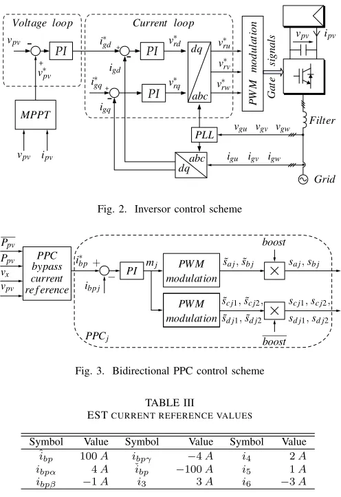
A conventional Voltage Oriented Control (VOC) scheme, composed by an outer dc-link voltage loop and two inner current loops (directigd and quadrature igq grid currents), is
applied to the2LV SI of the central inverter configuration as shown in Fig. 2. Wherevrdandvrq correspond respectively to
the direct and quadrature inverter voltages. The dc-link voltage referencev∗pvis generated by a traditional Perturb and Observe (P&O) Maximum Power Point Tracking algorithm.
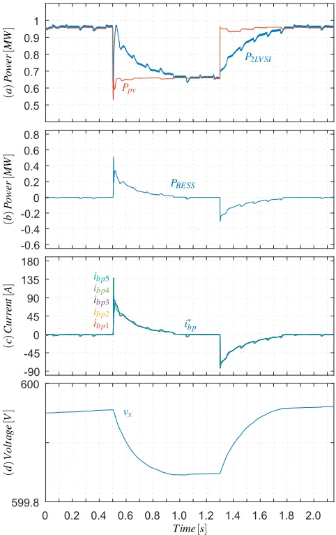
Figure 3 shows the control scheme applied to each PPC. The leftmost block (PPC bypass current reference), which is ex-plained through Fig. 4, generates the bypass current reference (i∗bp) for each interleaved PPC. A PI controller processes the error betweeni∗bp and the measurement of the bypass current in PPCj(ibpj), generating the modulation index, which is later
passed to the PWM modulation block generating the signals
˜
saj, ˜sbj, s˜cj1, s˜cj2, ˜sdj1 and s˜dj2. Later depending on the
power flow direction those signals are enabled (or disabled) by multiplying them by a signal named boost or its negated
boostgenerating the gate signalssaj,sbj,scj1,scj2,sdj1and sdj2, as shown in Fig. 3. When power flows towards the
+
-+
+
[image:4.612.51.299.48.409.2]-Fig. 2. Inversor control scheme
Fig. 3. Bidirectional PPC control scheme
TABLE III
ESTCURRENT REFERENCE VALUES
Symbol Value Symbol Value Symbol Value
ˆibp 100A ibpγ −4A i4 2A
ibpα 4A ˇibp −100A i5 1A
ibpβ −1A i3 3A i6 −3A
modulated, keeping scj1 =scj2 =sdj1 = sdj2 = 0. On the
other hand, when the power flows towards the battery pack,
boost is 0 (boost = 1) and gate signals scj1, scj2, sdj1 and sdj2 are modulated, whilesaj =sbj= 0.
PPC bypass current reference block (Fig. 3), operates ac-cording to the graph shown in Fig. 4. Where Ppv, Ppv, n, vpv,vx,vˇx,vˆxcorrespond respectively to the filtered PV plant
power, current PV plant power, number of interleaved PPCs, dc-link voltage, BESS current voltage, BESS minimum safety voltage (80%Depth of Discharge) and BESS maximum safety voltage (99% of Maximum battery pack voltage). When the quotient betweenλ= (Ppv−Ppv)/(n·vpv)is greater or equal
toi3 andˇvx< vx the reference i∗bp is given according to the
purple curve (top right). Ifλ≥i3, butvx<ˇvx, then i∗bp= 0.
On the other hand, whenλis lower thani4 andvx<vˆx, the
reference is given by the pink curve (bottom left). If λ < i4
butvˆx< vx, then the referencei∗bpis0. In order to keep BESS
voltage (vx) within a certain range, a charging strategy was
added to the bypass current reference generation algorithm,
i∗bp=ibpβ wheni6≤λ < i5 andvx<vˆx.
The parameter used in Fig. 4 are shown in table III.
IV. SIMULATIONRESULTS
[image:4.612.328.548.113.462.2]The circuital model of the full system was implemented in PLECS.
Fig. 4. PPC bypass current reference
TABLE IV
CONFIGURATION PARAMETERS.
PV power plant (under STC conditions)
Maximum power Ppv mpp 1M W
Open circuit voltage vpv ocv 970V
Short circuit current ipv sc 1327A
Maximum power point voltage vpv mpp 796V Maximum power point current ipv mpp 1256A
Modules connected in series Nsm 21
Strings connected in parallel Nps 140 2LVSI & Grid
PV 2LVSI dc-link capacitance Cpv 4400µF PV inverter dc-link voltage vpv 740−1000V
Grid voltage vac RM S 440VLL RM S
Grid inductance Lg 0.25mH
Grid frequency fg 50Hz
Switching frequency fsw 5kHz
Battery pack
Single cell capacity Ccell 6Ah
Maximum cell discharge rate Crate out 20C Maximum cell charge rate Crate in 19C
Number of cells Ncells 1211
BESS maximum safety voltage vˆx 649V BESS minimum safety voltage vˇx 480V
PPCs
PPC inductance L 1mH
PPC magnetising inductance Lm 1mH
PPC transformer ratio n1:n2 2 : 1
Switching frequency fbb 100kHz
Sampling period Ts 1µs
Table IV, shows the parameters applied in the simulation. A1M W PV plant was considered, based on Canadian Solar CS6X-340M-FG PV modules, a tailored battery pack formed by muRata6AhLiB battery cells was considered.
In order to validate the configuration two steps in solar irradiation were applied, while keeping temperature constant at
25◦C. The first step consists in a step-down in solar irradiation from1000to700W/m2at0.5[s], the second step corresponds
to a step-up from700to1000W/m2at1.3 [s]. The results of
the test are shown in the following charts. Fig. 5 shows the solar irradiation and inverter signals, sub-plot (a) shows the solar irradiation (G), sub-plot (b) displays the PV plant output current (ipv), sub-plot (c) shows the dc-link voltage (vpv)
and its reference (v∗pv), sub-plot (d) shows the grid currents in rotational (igd and igq) and stationary (igu, igv and igw)
reference frame.
instan-Fig. 5. PV plant and grid side converter signals: (a) Solar irradiation (G), (b) PV plant output current (ipv), (c)2LV SIdc-link voltage (vpv) and its
reference (v∗pv), (d)2LV SI grid currents in stationary (igu,igv andigw)
and rotational (igdandigq) reference frame.
taneous mismatch betweenipv and the grid currents (igu,igv
andigw) causes a fast decrease of the dc-link voltage (vpv) at t = 0.5s, which is instantaneously corrected by the 2LV SI
controller by decreasing the grid currents. The later increase and smooth decrease of grid currents (from 0.5 to 1.2s) is explained by the extra power injected to the dc-link by the BESS.
The step-up in solar irradiation (G) at 1.3 s generates a step-up in the PV plant output current (ipv). The instantaneous
mismatch between the grid currents and the PV plant output current generates a sudden increase in the dc-link voltage (vpv), which is corrected by the inverter control scheme by
increasing the grid currents. The smooth increase of the grid currents, despite the step-up inPpv (from1.3to2.0s), is due
to the power being stored in the BESS.
[image:5.612.54.292.53.439.2]It must be notice that the P&O algorithm keeps tracking the MPP dc-link voltage, even when the BESS is releasing or storing energy.
Fig. 6. System power and BESS signals: (a) Power injected to the grid (P2LV SI) and power provided by the PV plant (Ppv), (b) Power injected
to the dc-link by the BESS (PBESS), (c) PPCs bypass currents (ibp1,ibp2,
ibp3,ibp4andibp5) and its reference (i∗bp), (d) BESS terminal voltage (vx).
Fig. 7. Zoomed grid signals: grid currents (igu,igv andigw) and phaseu
grid voltage (vgu).
BESS, PV plant output power and 2LV SI output power signals are shown in Fig. 6. Sub-plot (a) shows the PV plant output power (Ppv) and the power injected to the grid by the
inverter (P2LV SI). The power released (positive) and stored
[image:5.612.314.555.54.437.2] [image:5.612.313.545.501.612.2]Sub-plot (c) shows the bypass currents (ibpj,j={1, . . . ,5})
and its reference (i∗bp). The terminal voltage across the battery pack (vx) is shown in sub-plot (d).
The step-down in solar irradiation at0.5scauses a positive difference between the average (Ppv) and the instantaneous
(Ppv) PV plant output power (hence λ > 0), commanding
the BESS to inject current (power) to the dc-link (from 0.5
to 1.2s). The power injected from the BESS mitigates the step-down in full system output power (P2LV SI), generating
a smooth transition. As the average PV plant output power decreases, the PPCs bypass current reference (i∗bp) decreases proportionally until reaching zero reference. The power drawn from the BESS towards the dc-link is reflected in a decrease of the battery pack terminal voltage (vx).
The step-up in solar irradiation at1.3sgenerates a negative difference between Ppv andPpv (λ <0), hence commanding
the BESS to take (store) energy from the dc-link, while smoothing the total system output power curve (from 1.3 to
2s). The negative value in BESS power (PBESS) represents
stored energy. As PBESS smoothly increases (towards zero)
proportionally increases the bypass current reference (i∗bp). The injection of power from the dc-link towards the BESS is reflected as an increase of the battery pack terminal voltage (vx).
V. CONCLUSION
This paper presents a bidirectional PPC as an interface to merge a battery pack to a grid-tied PV plant, in order to provide peak shaving capability. The BESS enables the PV system to store (release) exceeding (lacking) PV power, providing peak shaved power to the grid.
A full description and model of the system were given, providing a deeper understanding on how this bidirectional PPC operates. A tailored control strategy to manage the power flow between the battery pack and dc-link was tested, enabling the full system to inject peak shaved power to the grid. The standard P&O MPPT algorithm was able to operate normally, even when power was being drawn or injected to the dc-link by the BESS.
The proposed BESS configuration and control scheme were designed to be a plug-in solution for existing grid-tied PV plants, lacking peak shaving capability. Moreover, a small modification in the control strategy will allow BESS to mit-igate (avoid) PV plants power curtailment, required by grid operators to compensate grid frequency variations.
As a possible future work the authors propose the possibility to perform peak shaving and short term ancillary services without adding additional energy storage.
ACKNOWLEDGMENT
The authors gratefully acknowledge the financial support provided by FONDECYT 1171823, AC3E (CONICYT/BASAL/FB0008), SERC Chile (CONI-CYT/FONDAP/15110019) and CONICYT-PCHA/Doctorado Nacional/2014-21141092.
REFERENCES
[1] REN21,The First Decade 2004-2014 www.ren21.net. REN21, 2016. [2] REN21, Renewables 2017 Global Status Report www.ren21.net.
REN21, 2017.
[3] I. E. Commissionet al.,Grid Integration of Large-capacity Renewable Energy Sources and Use of Large-capacity Electrical Energy Storage: White Paper; October 2012. International Electrotechnical Commis-sion, 2012.
[4] J. Wid´en, N. Carpman, V. Castellucci, D. Lingfors, J. Olauson, F. Re-mouit, M. Bergkvist, M. Grabbe, and R. Waters, “Variability assessment and forecasting of renewables: A review for solar, wind, wave and tidal resources,” Renewable and Sustainable Energy Reviews, vol. 44, pp. 356–375, 2015.
[5] M. N. Hjelmeland, C. T. Larsen, M. Korp˚as, and A. Helseth, “Provision of rotating reserves from wind power in a hydro-dominated power system,” inProbabilistic Methods Applied to Power Systems (PMAPS), 2016 International Conference on. IEEE, 2016, pp. 1–7.
[6] J. Dong, F. Gao, X. Guan, Q. Zhai, and J. Wu, “Storage sizing with peak-shaving policy for wind farm based on cyclic markov chain model,”
IEEE Transactions on Sustainable Energy, vol. 8, no. 3, pp. 978–989, 2017.
[7] B.-R. Ke, T.-T. Ku, Y.-L. Ke, C.-Y. Chuang, and H.-Z. Chen, “Sizing the battery energy storage system on a university campus with prediction of load and photovoltaic generation,” IEEE Transactions on Industry Applications, vol. 52, no. 2, pp. 1136–1147, 2016.
[8] N. M¨uller, S. Kouro, H. Renaudineau, and P. Wheeler, “Energy storage system for global maximum power point tracking on central inverter pv plants,” in Power Electronics Conference (SPEC), IEEE Annual Southern. IEEE, 2016, pp. 1–5.
[9] N. M¨uller, H. Renaudineau, F. Flores-Bahamonde, S. Kouro, and P. Wheeler, “Ultracapacitor storage enabled global mppt for photovoltaic central inverters,” in Industrial Electronics (ISIE), 2017 IEEE 26th International Symposium on. IEEE, 2017, pp. 1046–1051.
[10] R. Sebasti´an, “Application of a battery energy storage for frequency regulation and peak shaving in a wind diesel power system,” IET Generation, Transmission & Distribution, vol. 10, no. 3, pp. 764–770, 2016.
[11] D. Wang, C. Ren, A. Sivasubramaniam, B. Urgaonkar, and H. Fathy, “Energy storage in datacenters: what, where, and how much?” inACM SIGMETRICS Performance Evaluation Review, vol. 40, no. 1. ACM, 2012, pp. 187–198.
[12] S. Sabihuddin, A. E. Kiprakis, and M. Mueller, “A numerical and graphical review of energy storage technologies,”Energies, vol. 8, no. 1, pp. 172–216, 2014.
[13] J. W. Zapata, H. Renaudineau, S. Kouro, M. A. Perez, and T. A. Mey-nard, “Partial power dc-dc converter for photovoltaic microinverters,” in
Industrial Electronics Society, IECON 2016-42nd Annual Conference of the IEEE. IEEE, 2016, pp. 6740–6745.
[14] J. W. Zapata, T. A. Meynard, and S. Kouro, “Partial power dc-dc converter for large-scale photovoltaic systems,” in Power Electronics Conference (SPEC), IEEE Annual Southern. IEEE, 2016, pp. 1–6. [15] A. Morrison, J. W. Zapata, S. Kouro, M. A. Perez, T. A. Meynard, and
H. Renaudineau, “Partial power dc-dc converter for photovoltaic two-stage string inverters,” inEnergy Conversion Congress and Exposition (ECCE), 2016 IEEE. IEEE, 2016, pp. 1–6.
[16] J. W. Zapata, T. A. Meynard, and S. Kouro, “Multi-channel partial power dc-dc converter for current balancing of led strings,” inIndustrial Electronics (ISIE), 2017 IEEE 26th International Symposium on. IEEE, 2017, pp. 775–780.
[17] J. Rojas, H. Renaudineau, S. Kouro, and S. Rivera, “Partial power dc-dc converter for electric vehicle fast charging stations,” in Industrial Electronics Society, IECON 2013-43rd Annual Conference of the IEEE. IEEE, 2017, pp. –.