arXiv:1612.03901v2 [cs.IT] 7 Jan 2017
Enhancing the Physical Layer Security of
Non-orthogonal Multiple Access in Large-Scale
Networks
Yuanwei Liu, Student Member, IEEE, Zhijin Qin, Student Member, IEEE, Maged Elkashlan, Member, IEEE,
Yue Gao, Senior Member, IEEE, and Lajos Hanzo, Fellow, IEEE
Abstract—This paper investigates the physical layer security of non-orthogonal multiple access (NOMA) in large-scale networks with invoking stochastic geometry. Both single-antenna and multiple-antenna aided transmission scenarios are considered, where the base station (BS) communicates with randomly dis-tributed NOMA users. In the single-antenna scenario, we adopt a protected zone around the BS to establish an eavesdropper-exclusion area with the aid of careful channel-ordering of the NOMA users. In the multiple-antenna scenario, artificial noise is generated at the BS for further improving the security of a beamforming-aided system. In order to characterize the secrecy performance, we derive new exact expressions of the security outage probability for both single-antenna and multiple-antenna aided scenarios. To obtain further insights, 1) for the single antenna scenario, we perform secrecy diversity order analysis of the selected user pair. The analytical results derived demonstrate that the secrecy diversity order is determined by the specific user having the worse channel condition among the selected user pair; and 2) for the multiple-antenna scenario, we derive the asymptotic secrecy outage probability, when the number of transmit antennas tends to infinity. Monte Carlo simulations are provided for verifying the analytical results derived and to show that: i) The security performance of the NOMA networks can be improved by invoking the protected zone and by generating artificial noise at the BS; and ii) The asymptotic secrecy outage probability is close to the exact secrecy outage probability.
Index Terms—Artificial noise, physical layer security, non-orthogonal multiple access, stochastic geometry
I. INTRODUCTION
The unprecedented expansion of new Internet-enabled smart devices, applications and services is expediting the develop-ment of the fifth generation (5G) networks, which aim for substantially increasing the throughput of the fourth generation (4G) networks. In addition to the key technologies such as large-scale multiple-input multiple-output (MIMO) solutions, heterogeneous networks and millimeter wave, as well as novel multiple access (MA) techniques should be invoked for improving the spectral efficiency. The existing MA techniques can be primarily classified into two main categories, namely orthogonal multiple access and non-orthogonal multiple access (NOMA), by distinguishing whether a specific resource block
Part of this work was presented at the IEEE International Conference on Communications (ICC), Kuala Lumpur, Malaysia, May 2016 [1].
Y. Liu, Z. Qin, M. Elkashlan, and Y. Gao are with Queen Mary Uni-versity of London, London, UK (email:{yuanwei.liu, z.qin, maged.elkashlan, yue.gao}@qmul.ac.uk).
L. Hanzo is with University of Southampton, Southampton, UK (email:[email protected]).
can be occupied by more than one user [2]. More specifically, upon investigating the multiplexing gain gleaned from the different domains, the NOMA technique can be further clas-sified as code-domain NOMA and power-domain NOMA [3]. Power-domain NOMA1, which has been recently proposed
for the 3GPP Long Term Evolution (LTE) initiative [4], is deemed to have a superior spectral efficiency [5, 6]. It has also been pointed out that NOMA has the potential to be integrated with existing MA paradigms, since it exploits the new dimension of the power domain. The key idea of NOMA is to ensure that multiple users can be served within a given resource slot (e.g., time/frequency), by applying successive in-terference cancellation (SIC). The concept of SIC, which was first proposed by Cover in 1972 [7], constitutes a promising technique, since it imposes lower complexity than the joint decoding approach [8].
Hence NOMA techniques have received remarkable atten-tion both in the world of academia and industry [9–13]. Ding
et al. [9] investigated the performance of the NOMA downlink
for randomly roaming users. It was shown that NOMA is indeed capable of achieving a better performance than their traditional orthogonal multiple access (OMA) counter parts. By considering the user fairness of a NOMA system, a user-power allocation optimization problem was addressed by Tim-otheou and Krikidis [10]. A cooperative simultaneous wireless power transfer (SWIPT) aided NOMA protocol was proposed by Liu et al. [11], where a NOMA user benefitting from good channel conditions acts as an energy harvesting source in order to assist a NOMA user suffering from poor channel condi-tions. With the goal of maximizing the energy efficiency of transmission in multi-user downlink NOMA scenarios, Zhang
et al. [14] proposed an efficient power allocation technique
capable of supporting the data rate required by each user. To further improve the performance of NOMA systems, multiple antennas were introduced in [12, 13]. More particularly, the application of multiple-input single-output (MISO) solution to NOMA was investigated by Choi et al. [12], where a two-stage beamforming strategy was proposed. Power optimization was invoked by Sun et al. [13] for maximizing the ergodic capacity of MIMO aided NOMA systems. As a further advance, a massive multiple-input multiple-output (MIMO) aided hybrid heterogenous NOMA framework was proposed for downlink 1Hence in this paper, we focus our attention on the family of power-domain
transmission by Liu et al. [15]. The impact of the locations of users and interferers was investigated by using stochastic geometry approaches.
Given the broadcast nature of wireless transmissions, the concept of physical (PHY) layer security (PLS) was proposed by Wyner as early as 1975 from an information-theoretical perspective [16]. This research topic has sparked of wide-spread recent interests. To elaborate, PLS has been considered from a practical perspective in [17–21]. Specifically, robust beamforming transmission was conceived in conjunction with applying artificial noise (AN) for mitigating the impact of imperfect channel state information (CSI) in MIMO wiretap channels was proposed by Mukherjee and Swindlehurst [17]. Ding et al. [18] invoked relay-aided cooperative diversity for increasing the capacity of the desired link. More particularly, the impact of eavesdroppers on the diversity and multiplexing gains was investigated both in single-antenna and multiple-antenna scenarios. Additionally, the tradeoffs between secure performance and reliability in the presence of eavesdropping attacks was identified by Zou et al. [20]. Furthermore, the physical layer security of D2D communication in large-scale cognitive radio networks was investigated by Liu et al. [21] with invoking a wireless power transfer model, where the positions of the power beacons, the legitimate and the eaves-dropping nodes were modeled using stochastic geometry.
Recently, various PHY layer techniques, such as cooperative jamming [22] and AN [23] aided solutions were proposed for improving the PLS, even if the eavesdroppers have better channel conditions than the legitimate receivers. A popular technique is to generate AN at the transmitter for degrading the eavesdroppers’ reception, which was proposed by Goel and Negi in [23]. In contrast to the traditional view, which regards noise and interference as a detrimental effect, generating AN at the transmitter is capable of improving the security, because it degrades the channel conditions of eavesdroppers without affecting those of the legitimate receivers. An AN-based multi-antenna aided secure transmission scheme affected by colluding eavesdroppers was considered by Zhou and McKay [24] for the scenarios associated both with perfect and imperfect CSI at both the transmitter and receiver. As a further development, the secrecy enhancement achieved in wireless Ad Hoc networks was investigated by Zhang et al. [25], with the aid of both beamforming and sectoring techniques. By simultaneously considering matched filter precoding and AN generation techniques, the secure transmission strategies for a multi-user massive MIMO systems was investigated by Wu et
al. [26]. Very recently, the PLS of a single-input single-output
(SISO) NOMA system was studied by Zhang et al. [27], with the objective of maximizing the secrecy sum rate of multiple users.
A. Motivation and Contribution
As mentioned above, PLS has been studied in various scenarios, but there is still a paucity of research contributions on investigating the security issues of NOMA, which motivates this contribution. Note that the employment of SIC in NOMA results in a unique interference status at the receivers, which
makes the analysis of the PLS of NOMA different from that of OMA. In this paper, we specifically consider the scenario of large-scale networks, where a base station (BS) supports randomly roaming NOMA users. In order to avoid sophisti-cated high-complexity message detection at the receivers, a user pairing technique is adopted for ensuring that only two users share a specific orthogonal resource slot, which can be readily separated by low-complexity SIC. A random number of eavesdroppers are randomly positioned on an infinite two-dimensional plane according to a homogeneous Poisson point process (PPP). An eavesdropper-exclusion zone is introduced around the BS for improving the secrecy performance of the large-scale networks considered in which no eavesdroppers are allowed to roam. This ‘disc’ was referred to as a protected zone in [25, 28, 29]. Specifically, we consider both a single-antenna scenario and a multiple-single-antenna scenario at the base station (BS). 1) For the single-antenna scenario, M NOMA users are randomly roaming in an finite disc (user zone) with the quality-order of their channel conditions known at the BS. For example, the m-th NOMA user is channel-quality order of m. In this case, the m-th user is paired with the n-th user for transmission within the same resource slot; 2) For the multiple-antenna scenario, we invoke beamforming at the BS for generating AN. In order to reduce the complexity of channel ordering of MISO channels for NOMA, we partitioned the circular cell of Fig. 1 into an internal disc and an external ring. We select one user from the internal disc and another from the external ring to be paired together for transmission within the same resource slot using a NOMA protocol. The primary contributions of this paper are as follows:
• We investigate the secrecy performance of large-scale NOMA networks both for a single-antenna aided and a multiple-antenna assisted scenario at the BS. A protected zone synonymously referred to as the eavesdropper-exclusion area, is invoked in both scenarios for improving the PLS. Additionally, we propose to generate AN at the BS in the multiple-antenna aided scenario for further enhancing the secrecy performance.
• For the single-antenna scenario, we derive the exact analytical expressions of the secrecy outage probabil-ity (SOP) of the selected pair of NOMA users, when relying on channel ordering. We then further extend on the secrecy diversity analysis and derive the expressions of asymptotic SOP. The results derived confirm that: 1) for the selected pair, them-th user is capable of attaining a secrecy diversity order of m; 2) the secrecy diversity order is determined by the one associated with the worse channel condition between the paired users.
• It is shown that: 1) the SOP can be reduced both by extending the protected zone and by generating AN at the BS; 2) the asymptotic SOP results of our large antenna array analysis is capable of closely approximating the exact secrecy outage probability; 3) there is an optimal desired signal-power and AN power sharing ratio, which minimizes the SOP in the multi-antenna scenario.
B. Organization
The rest of the paper is organized as follows. In Section II, a single-antenna transmission scenario is investigated in random wireless networks, where channel ordering of the NOMA users is relied on. In Section III, a multiple-antenna transmission scenario is investigated, which relies on generating AN at the BS. Our numerical results are presented in Section IV for verifying our analysis, which is followed by our conclusions in Section V.
II. PHYSICALLAYERSECURITY INRANDOMWIRELESS
NETWORKS WITHCHANNELORDERING
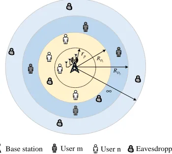
As shown in Fig. 1, we focus our attention on a secure downlink communication scenario. In the scenario considered, a BS communicates with M legitimate users (LUs) in the presence of eavesdroppers (Eves). We assume that theM users are divided into M/2orthogonal pairs. Each pair is randomly allocated to a single resource block, such as a time slot or an orthogonal frequency band. For simplicity, we only focus our attention on investigating a typical pair of users in this treatise. Random user-pairing is adopted in this work2. For each pair, the NOMA transmission protocol is invoked. It is assumed that BS is located at the center of a disc, denoted by D, which has a coverage radius of RD (which is defined as the user zone for NOMA [9]). TheM randomly roaming LUs are uniformly distributed within the disc. A random number of Eves is distributed across an infinite two-dimensional plane, which are assumed to have powerful detection capabilities and can overhear the messages of all orthogonal RBs, i.e. time slots or frequency slots. The spatial distribution of all Eves is modeled using a homogeneous PPP, which is denoted by Φe and it is associated with the densityλe. It is assumed that the Eves can be detected, provided that they are close enough to BS. Therefore, an Eve-exclusion area having a radius of rp is introduced. Additionally, all channels are assumed to impose quasi-static Rayleigh fading, where the channel coefficients are constant for each transmission block, but vary independently between different blocks.
[image:3.612.355.515.57.212.2]Without loss of generality, it is assumed that all the channels between the BS and LUs obey|h1|2≤ · · ·|hm|2≤ · · ·|hn|2≤
···|hM|2. Both the the small-scale fading and the path loss are incorporated into the ordered channel gain. Again, we assume that the m-th user and the n-th user (m < n) are paired for transmission in the same resource slot. Without loss of generality, we focus our attention on a single selected pair of users in the rest of the paper. In the NOMA transmission 2We note that however sophisticated user pairing is capable of enhancing
the performance of the networks considered [11], which is set aside for our future work.
D R
∞
User Eavesdropper
p r
Base station
Fig. 1: Network model for secure NOMA transmission in single-antenna scenario, whererp, RD, and ∞ is the radius of the Eve-exclusion area, NOMA user zone, and an infinite two dimensional plane for Eves, respectively.
protocol, more power should be allocated to the user suffering from worse channel condition [5, 6]. Therefore, the power allocation coefficients satisfy the conditions that am > an and am+an = 1. By stipulating this assumption, SIC can be invoked by the n-th user for first detecting the specific user having a higher transmit power (TX-power), who hence has a less interference-infested signal. Accordingly, the m -th user’s signal is -then remodulated and deducted from -the original composite signal. This procedure then directly delivers the decontaminated lower-TX-power signal of the n-th user itself3. We assume having fixed power allocation sharing between two users, but optimal power sharing strategies are capable of further enhancing the performance of the networks considered, which is beyond the scope of this paper. Based on the aforementioned assumptions, the instantaneous SINR of the m-th user and the signal-to-noise ratio (SNR) of the
n-th user can be written as:
γBm =
am|hm|2
an|hm|2+ρ1b
, (1)
γBn=ρban|hn|
2
, (2)
respectively. We introduce the convenient concept of transmit SNRρb=PσT2
b
, wherePT is the TX-power of composite signal at the BS andσ2
b is the variance of the additive white Gaussian noise (AWGN) at the LUs, noting that this is not a physically measurable quantity owing to their geographic separation. Perfectly flawless detection is assumed in this treatise, which is realistic at today’s state-of-the-art with the aid of iterative turbo-detection techniques [30, 31]. Additionally, a bounded path loss model is used for guaranteeing that there is a practical path-loss, which is higher than one even for small distances.
3It is assumed that perfect SIC is achieved at the n-th user, although
We consider the worst-case scenario of large-scale networks, in which the Eves are assumed to have powerful detection capabilities [25, 32]. Specifically, by applying multiuser detec-tion techniques, the multiuser data stream received from BS can be distinguished by the Eves, upon subtracting interference generated by the superposed signals from each other. In fact, this assumption overestimates the Eves’ multi-user decodabil-ity. In the scenario considered, all the CSIs of the LUs are assumed to be known at BS. However, the CSIs of Eves are assumed to be unknown at the BS. The most detrimental Eve is not necessarily the nearest one, but the one having the best channel to BS. Non-colluding eavesdroppers are considered in this work. Therefore, the instantaneous SNR of detecting the information of the m-th user and the n-th user at the most detrimental Eve can be expressed as follows:
γEκ=ρeaκ max
e∈Φe,de≥rp
n
|ge|2L(de) o
. (3)
It is assumed that κ∈ {m, n},ρe= PσT2
e is the transmit SNR
withσ2
ebeing the variance of the AWGN at Eves. Additionally,
ge is defined as the small-scale fading coefficient associated with ge∼ CN(0,1),L(de) = d1α
e is the path loss, and de is
the distance from Eves to BS. Note that due to the existence of the Eve-exclusion area (we assumerp>1), it is not required to bound the path loss for Eves sincedewill always be larger than one.
A. New Channel Statistics
In this subsection, we derive several new channel statistics for LUs and Eves, which will be used for deriving the secrecy outage probability in the next subsection.
Lemma 1. Assuming M randomly located NOMA users in the disc of Fig. 1, the cumulative distribution function (CDF)
FγBn of then-th LU is given by
FγBn(x)≈ϕn
M−n X
p=0
M −n p
(−1)p
n+p×
X
˜ Snp
n+p
q0+· · ·+qK
K
Y
K=0
bqk
k !
e− K P
k=0
qkckρbanx , (4)
where K is a complexity-vs-accuracy tradeoff parameter,
bk = −ωK p
1−φ2
k(φk+ 1), b0 = − K P
k=1
bk, ck = 1 +
RD
2 (φk+ 1)
α
, ωK = Kπ, φk = cos 22kK−1π, S˜np =
(q0, q1,· · · , qK)| K P
i=0
qi =n+p
, q n+p 0+···+qK
= q(n+p)!
0!···qK!
andϕn= (M−nM)!(!n−1)!.
Proof: See Appendix A .
Lemma 2. Assuming M randomly positioned NOMA users in the disc of Fig. 1, the CDF FγBm of the m
-th LU is given in (5) at -the top of next page, where
U(x) =
(
1, x >0
0, x≤0 is the unit step function , and S˜mp =
(q0, q1,· · · , qK)| K P
i=0
qi =m+p
.
Proof: Based on (1), the CDF of FγBm(x) can be expressed as
FγBm(x) =
Pr
|hm|2<
x
(am−anx)ρb
| {z }
Φm
, x < am
an
1, x≥ am
an
.
(6)
To derive the CDF of FγBm(x), Φm can be expressed as
Φm = F|hm|2
x (am−anx)ρb
. Based on (A.5), interchanging the parameters m → n and applying y = x
(am−anx)ρb, we obtain
Φm=ϕm M−m
X
p=0
M−m p
(−1)p
m+p×
X
˜ Spm
m+p
q0+· · ·+qK
K
Y
k=0
bqk
k !
e− K P
k=0
qkck(am−xanx)ρb . (7)
By substituting (7) into (6), with the aid of the unit step function, the CDF of FγBm(x) can be obtained. The proof is completed.
Lemma 3. Assuming that the eavesdroppers obey the PPP
distribution and the Eve-exclusion zone has a radius of rp, the probability density function (PDF) fγEκ of the most
detrimental Eve (whereκ∈ {m, n}) is given by
fγEκ(x) =µκ1e
−µκ1 Γ(δ,µκ2x)
xδ
µδ
κ2e−µκ2x
x +
δΓ (δ, µκ2x)
xδ+1
,
(8) whereµκ1=δπλe(ρeaκ)δ, µκ2=
rα p
ρeaκ,δ=
2
α andΓ(·,·) is the upper incomplete Gamma function.
Proof: To derive the PDF offγEκ(x), we have to compute the CDF ofFγEκ firstly as
FγEκ(x) =EΦe
Y
e∈Φe,de≥rp F|ge|2
xdα
e
ρeaκ
. (9)
Following the similar approach as [33], by applying the generating function [34], (9) can be rewritten as
FγEκ(x) = exp
−λe
Z
R2
1−F|ge|2
xdα e
ρeaκ
rdr
= exp
"
−2πλe
Z ∞
rp
re−ρe aκx r α
dr
#
. (10)
By applying [35, Eq. (3.381.9)], we arrive at:
FγEκ(x) =e
−
δπλe(ρe aκ)δΓ δ,xrαp ρe aκ !
xδ . (11)
FγBm(x)≈U
x−aam
n
+U
am
an −
x
ϕm M−m
X
p=0
M −m p
(−1)p
m+p
X
˜ Smp
m+p q0+· · ·+qK
K
Y
k=0
bqk
k !
e− K P
k=0
qkck(am−xanx)ρb.
(5)
B. Secrecy Outage Probability
In the networks considered, the capacity of the LU’s channel for the κ-h user (κ∈ {m, n} ) is given byCBκ = log2(1 + γBκ), while the capacity of the Eve’s channel for the κ-th
user is quantified byCEκ = log2(1 +γEκ). It is assumed that
the length of the block is sufficiently high for facilitating the employment of capacity-achieving codes within each block. Additionally, the fading block length of the main channel and of the eavesdropper’s channel are assumed to be the same. As such, according to [36], the secrecy rate of then-th and of the
m-th user can be expressed as
Cn= [CBn−CEn]
+
, (12)
Cm= [CBm−CEm]
+
, (13)
where we have [x]+= max
{x,0}. Here, the secrecy rates of LUs are strictly positive [37]. Recall that the Eves’ CSIs are unknown at the BS, hence the BS can only send information to the LUs at a constant rate, but perfect secrecy is not always guaranteed [38]. Considering the κ-th user as an example, if
Rκ < Cκ, the information with a rate of Rκ (κ ∈ {m, n} is conveyed in perfect secrecy. By contrast, for the case of
Rκ > Cκ the information-theoretic security is compromised. Motivated by this, secrecy outage probability is used as our secrecy performance metric in this paper. Given the expected secrecy rate Rκ of the κ-th user, a secrecy outage event is declared, when the secrecy rate Cκ drops below Rκ, which is defined as the SOP for the κ-th user. Recall that we have allocatedM users toM/2orthogonal RBs, each pair of users are independent from all other pairs of users. We focus our attention on the SOP of a typical pair of users. We then derive the SOP of the κ-th user in the following two Theorems. We consider the SOP under the condition that the connection between BS and LUs can be established.
Theorem 1. Assuming that the LUs position obeys the PPP
for the ordered channels of the LUs, the SOP of then-th user is given by (14) at the top of this page.
Proof: In this treatise, we consider the SOP under the condition that the connection between the BS and LUs can be established. As such, the SIC has been assumed to be successfully performed at the n-th user. Based on (12), the SOP is given by
Pn(Rn) =
Z ∞
0
fγEn(x)FγBn 2
Rn(1 +x)
−1dx. (15)
Upon using the results of Lemma 1 and Lemma 3, substi-tuting (4) and (8) into (15), after some further mathematical manipulations, we can express the SOP of then-th user. The proof is completed.
Theorem 2. Assuming that the LUs position obeys the PPP
for the ordered channels of the LUs, the SOP of the m-th user is given by (16) at the top of next page, where we have
τm= 2Rm(1−1 am)−1.
Proof: Based on (13) and according to [37], the SOP for them-th user is given by
Pm(Rm) =
Z ∞
0
fγEm(x)FγBm 2
Rm(1 +x)−1dx.
(17)
Upon using the results of Lemma 2 and Lemma 3, as well as substituting (5) and (8) into (17), after some further mathematical manipulations, we can express the SOP of the m-th user. The proof is completed.
In this paper, based on the assumptions of perfect SIC of LUs and strong detection capabilities of Eves aforementioned, the secrecy outage occurs in them-th user and then-th user are independent. Note that relaxing these two assumptions requires to consider dependence between two users by discussing more sophisticated connect/secrecy outage events, which should be included in our future work with the aid of the results derived in this paper. In other words, the SOP of the m-th user has no effect on the SOP of the n-th user and vice versa. As a consequence, we define the SOP for the selected user pair as that of either them-th user or then-th user outage.
Proposition 1. The SOP of the selected user pair is given by
Pmn= 1−(1−Pm) (1−Pn), (18)
wherePn andPm are given by (14) and (16), respectively.
C. Secrecy Diversity Order Analysis
In order to derive the secrecy diversity order to gain further insights into the system’s operation in the high-SNR regime, the following new analytical framework is introduced. Again, as the worst-case scenario, we assume that Eves have a powerful detection capability. The asymptotic behavior is analyzed, usually when the SNR of the channels between the BS and LUs is sufficiently high, i.e., when the BS’s transmit SNR obeys ρb → ∞, while and the SNR of the channels between BS and Eves is set to arbitrary values. It is noted that for the Eve’s transmit SNR ofρe → ∞, the probability of successful eavesdropping will tend to unity. The secrecy diversity order can be defined as follows:
ds=− lim ρb→∞
logP∞
logρb
, (19)
Pn(Rn) =ϕn M−n
X
p=0
M −n p
(−1)p
n+p
X
˜ Spn
n+p q0+· · ·+qK
K
Y
K=0
bqk
k !
×
Z ∞
0
µn1
µδ
n2e−µn2x
x +
δΓ (δ, µn2x)
xδ+1
e−
µn1Γ(δ,µn2x)
xδ −
K P
k=0
qkck2
Rn(1+x)−1
ρban dx. (14)
Pm(Rm) =1−e
−µm1 Γ(δ,τm µm2)
τm δ +ϕm
M−m X
p=0
M
−m p
(
−1)p
m+p
X
˜ Smp
m+p
q0+· · ·+qK
K
Y
k=0
bqk
k !
×
Z τm
0
µm1
µδ
m2e−µm2x
x +
δΓ (δ, µm2x)
xδ+1
e−
µm1 Γ(δ,µm2x)
xδ −
K P
k=0
qkck
2Rm(1+x)−1
(am−an(2Rm(1+x)−1))ρbdx. (16)
Corollary 1. Assuming that the LUs position obeys the PPP
for the ordered channels of the LUs, the asymptotic SOP of the n-th user is given by
P∞
n (Rn) =Gn(ρb)−Dn+o
ρ−Dn
b
, (20)
where we have Q1=R ∞ 0 µn1e
−µn1Γ(δ,µn2x)
xδ ×
µδ
n2e−µn2x
x +
δΓ(δ,µn2x)
xδ+1
(2Rn(1+x)−1)ℓ
an
n
dx,
Gn =ϕnnQ1, andDn =n.
Proof: We commence our diversity order analysis by characterizing the CDF of the LUs F∞
γBm and F
∞
γBn in the high-SNR regime. When y → 0, based on (A.3) and the approximation of 1 −e−y ≈ y, we obtain the asymptotic
unordered CDF of
˜hn
2
as follows:
F∞
|˜hn|2(y)≈
2y R2 D
Z RD
0
(1 +rα)rdr=yℓ, (21)
whereℓ= 1+2RαD
α+2. Substituting (21) into (A.2), the asymptotic
unordered CDF of
˜hn
2
is given by
F|∞hn|2(y) =ϕn
M−n X
p=0
M−n p
(−1)p
n+p(yℓ)
n+p
≈ϕnn(yℓ)n.
(22)
Then based on (A.1), we can obtainFγ∞Bn(x)≈
ϕn
n
xℓ ρban
n
. Based on (15), we can replace the CDF of FγBn by the asymptoticF∞
γBn. After some manipulations, we arrive at the asymptotic SOP of then-th user. The proof is completed.
Remark 1. Upon substituting (20) into (19), we obtain the
secrecy diversity order of the n-th user isn.
Corollary 2. Assuming that the LUs position obeys the PPP
for the ordered channels of the LUs, the asymptotic SOP for the m-th user is given by
Pm∞(Rn) =Gm(ρb)−Dm+o
ρ−Dm
b
, (23)
where we haveQ2=R0τmµm1e−
µm1Γ(δ,µm2x)
xδ ×
µδ
m2e−µm2x
x +
δΓ(δ,µm2x)
xδ+1
(2Rm(1+x)−1)ℓ
(am−an(2Rm(1+x)−1))
m
dx,
Gm= ϕmmQ2 andDm=m.
Proof: Based onΦm and (22), we can arrive at:
Φ∞m≈ϕm
m
xℓ
(am−anx)ρb
m
. (24)
Substituting (24) into (6), the asymptotic CDF ofγBm can be expressed as
Fγ∞Bm(x) =U
x−aam
n
+U
am
an −
x
Φ∞m, (25)
where Φ∞
m is given in (24). Then, based on (17), we can
replace the CDF of FγBm by the asymptotic F
∞
γBm of (25). Additionally, we can formulate the asymptotic SOP of them-th user. The proof is completed.
Remark 2. Upon substituting (23) into (19), we obtain the
secrecy diversity order of them-th user ism.
Proposition 2. Form < n, the secrecy diversity order can be expressed as
ds=− lim ρb→∞
log (P∞
m +Pn∞−Pm∞Pn∞)
logρb
=m. (26)
Proof: Based on Corollary 2 and Corollary 1, and upon substituting (20) and (23) into (18), the asymptotic SOP for the user pair can be expressed as
Pmn∞ =Pm∞+Pn∞−Pm∞Pn∞≈Pm∞Gm(ρb)−Dm. (27)
Upon substituting (27) into (19), we arrive at (26). The proof is completed.
Remark 3. The results of (26) indicate that the secrecy
diversity order and the asymptotic SOP for the user pair considered are determined by them-th user.
Remark 3 provides insightful guidelines for improving the
User m Eavesdropper
p r
Base station
1 D R
2
D R
User n
[image:7.612.86.261.55.212.2]∞
Fig. 2: Network model for secure NOMA transmission using AN in multiple-antenna scenario, where rp, RD1, RD2, and ∞is the radius of the Eve-exclusion zone, NOMA user zone for usern, NOMA user zone for user m, and an infinite two dimensional plane for eavesdroppers, respectively.
III. ENHANCINGSECURITY WITH THE AID OFARTIFICIAL
NOISE
In addition to single antenna scenario [1], for further im-proving the secrecy performance, let us now consider the employment of multiple antennas at BS for generating AN in order to degrade the Eves’ SNR. More particularly, the BS is equipped with NA antennas, while all LUs and Eves are equipped with a single antenna each. Here, NA > 2 is assumed for ensuring the existence of a null-space for two NOMA users. We mask the superposed information of NOMA by superimposing AN on Eves with the aid of the BS. It is assumed that the perfect CSI of LUs are known at BS4. Since the AN is in the null space of the intended LU’s
channel, it will not impose any effects on LUs. However, it can significantly degrade the channel and hence the capacity of Eves. More precisely, the key idea of using AN as proposed in [39] can be described as follows: an orthogonal basis of
CNA is generated at BS for userκ, (whereκ∈ {m, n}) as a
(NA×NA)–element precoding matrixUκ= [uκ,Vκ], where we haveuκ=h
† κ .
khκk, andVκ is of sizeNA×(NA−1). Here, hκ is denoted as the intended channel between the BS and userκ. It is noted that each column ofVκis orthogonal to
uκ. Beamforming is applied at the BS for generating AN. As such, the transmitted superposed information, which is masked by AN at the BS is given by
X
κ∈{m,n} √a
κxκ= X
κ∈{m,n} √a
κ(sκuκ+tκVκ), (28)
wheresκ is the information-bearing signal with a variance of
σ2
s, andtκ is the AN. Here the (NA−1) elements of tκ are independent identically distributed (i.i.d.) complex Gaussian random variables with a variance of σ2
a. As such, the overall power per transmission isPT =PS+PA, wherePS =θPT = 4In practical scenarios, estimating the CSI may be a non-trivial task,
therefore, our work actually provides an upper bound in terms of the attainable secrecy performance.
σ2
s is the transmission power of the desired information-bearing signal, while PA= (1−θ)PT = (NA−1)σa2 is the transmission power of the AN. Here θ represents the power sharing coefficients between the information-bearing signal and AN.
As shown in Fig. 2, we divide the discD into two regions, namely, D1 and D2, respectively. The motivation of using this topology hinges on two aspects. The first one is to create more distinct channel quality differences between the paired users, since existing NOMA studies have demonstrated that it is beneficial to pair two users having rather different channel conditions [5, 11, 40]. The second one is that of reducing the complexity of channel ordering in this MISO NOMA system, which provides a compelling flexibility. By doing so, the path loss is the dominant channel impairment in this scenario, be-cause compared to the instantaneous small-scale fading effects, the path loss is more stable and more dominant. A quantitative example of comparing the small-scale fading and path loss was provided in Chapter 2 of [41]. Note that the proposed design cannot guarantee the optimal ordering for MISO NOMA chan-nels. More sophisticated precoding/detection design strategies (e.g., cluster based design, signal alignment and etc.) can be developed for further enhancing the attainable performance of the networks considered [42, 43], but this is beyond the scope of this treatise. Here,D1 is an internal disc with radius
RD1, and the group of user n is located in this region. D2
is an external ring spanning the radius distance fromRD1 to RD2, and the group of userm is located in this region. For
simplicity, we assume that usernand usermare the selected user from each group in the rest of this paper. The cell-center usernis assumed to be capable of cancelling the interference of the cell-edge user m using SIC techniques5. User n and
usermare randomly selected in each region for pairing them for NOMA. The combined signal at usermis given by
ym=
hmum√amsm p
1 +dα m
| {z }
Signal part
+hmun
√a
nsn p
1 +dα m
+hmVn
√a
ntn p
1 +dα m
+nm
| {z }
Interference and noise part ,
(29) where nm is a Gaussian noise vector at user m, while dm is the distance between the BS and userm. Substituting (28) into (29), the received SINR at userm is given by
γBANm =
amσs2khmk 2
anσs2
hm h
†
n
khnk
2
+anσ2akhmVnk2+ 1 +dαm
, (30)
where the variance ofnmis normalized to unity. As such, we can express the transmit SNR at BS asρt=PT.
Since SIC is applied at usern, the interference arriving from user m can be detected and subtracted firstly. The aggregate
5Note that upon invoking the signal alignment technique [43], the BS is
signal at user nis given by
yn =
hnun√ansn p
1 +dα n
| {z }
Signal part
+ hnVm
√a
mtm p
1 +dα n
+nn
| {z }
Interference and noise part
, (31)
where nn is the Gaussian noise at user n, while dn is the distance between the BS and user n. The received SINR at usern is given by
γAN Bn =
anσs2khnk2
amσa2khnVmk2+ 1 +dαn
, (32)
where the variance of nn is normalized to unity. The signal observed by Eves is given by
ye= X
κ∈{m,n}
he√aκxκ p
dα e
+ne, (33)
wherene is the Gaussian noises at Eves, whilehe∈C1×NA is the channel vector between the BS and Eves. Similar to the single-antenna scenario, again, we assume that the Eves have a strong detection capability and hence they unambiguously distinguish the messages of user mand usern. The received SINR of the most detrimental Eve associated with detecting userκis given by
γEANκ =aκσ
2 s max
e∈Φe,de≥rp
Xe,κ
IAN e +dαe
, (34)
where the variance of neis normalized to unity, and we have
Xe,κ =
he h
†
κ
khκk
2
as well as IAN
e = amσ2akheVmk2 +
anσ2akheVnk2.
A. New Channel Statistics
In this subsection, we derive several new channel statistics for LUs and Eves in the presence of AN, which will be used for deriving the SOP in the next subsection.
Lemma 4. Assuming that user n is randomly positioned in the discD1of Fig. 2, the CDF of FBANn is given by
FAN
Bn (x) = 1−b2e
−ϑx am
NA−1
X
p=0
ϑpxp
p! p X q=0 p q ×
Γ (NA−1 +q)aqm−p
ϑx+NA−1
PA
NA−1+q
p−q X
u=0
p−q u
au+δ
m γ
u+δ,ϑx amR
α D1
(ϑx)u+δ ,
(35) where we haveb2= δ
R2
D1Γ(NA−1)
PA
NA−1
NA−1 andϑ= aanmPS. Proof: See Appendix B.
Lemma 5. Assuming that user m is randomly positioned in the ring D2 of Fig. 2, for the case of θ6= N1A, the CDF of
FAN
Bm is given by FBANm (x) = 1−e
−νx an
NA−1
X
p=0
(νx)p
p! p X q=0 p q
aqn−p×
a1
Γ (q+ 1)
νx+P1
S
q+1 −
NA−2
X
l=0
NA−1
PA −
1 PS
l
l!νx+NAPA−1q+l+1 Γ(q+l+1)
| {z }
I(θ)
×
p−q X
u=0
p−q u
γu+δ,νx
anR
α D2
−γu+δ,νx anR
α D1 νx an
u+δ , (36)
where γ(·,·) is the lower incomplete Gamma function, Γ (·) is the Gamma function, a1 =
δ1− PA
(NA−1)PS
1−NA
/ R2 D2−R
2 D1 PS , and
ν= an
amPS.
For the case of θ=N1A, the CDF of FAN
Bm is given by
(36) upon substitutingI (θ)byI∗(θ), where we haveI∗(θ) = a2Γ(q+NA)
νx+ 1 PS
q+NA
p−q P
u=0 p−q
u
anda2= δ
R2 D2−R
2 D1
PSNA(NA−1)!
.
Proof: See Appendix C.
Lemma 6. Assuming that the distribution of Eves obeys a
PPP and that the Eve-exclusion zone has a radius of rp, the PDF offγAN
Eκ (whereκ∈ {m, n}) is given by fγAN
Eκ (x) =−e
ΘκΨκ1× µAN
κ2
δ
e−xµANκ2 x Ψκ1+
δΘκΨκ1
x + ΘκΨκ2
!
, (37)
where Θκ =
Γ(δ,xµAN κ2 )
xδ , Γ (·,·) is the upper
incom-plete Gamma function, Ψκ1 = Ω 1 x aκ PS+τi
j,Ψκ2 =
Ω 1
x aκ PS+τi
j
j
x aκ PS+τi
1 aκPS
,Ω = (−1)NA µAN
κ1 × 2
Q
i=1
τNA−1
i 2 P
i=1 NPA−1
j=1
aNA−j,NA−1(2τi−L)
j−(2NA−2) , L = τ1+τ2, τ1=NamAP−1A, τ2=NanAP−1A,aNA−j,NA−1=
2NA−j−3
NA−j−1
,
µAN
κ1 =πλeδ(aκPS)δ, andµANκ2 = rα
p
aκPS. Proof: See Appendix D.
B. Secrecy Outage Probability
In this subsection, we investigate the SOP of a multiple-antenna aided scenario relying on AN.
Theorem 3. Assuming that the LUs and Eves distribution
obey PPPs and that AN is generated at the BS, the SOP of usern is given by (38) at the top of next page, whereιn∗=
ϑ(2Rn(1+x)−1)
am .
Proof: Using the results of Lemma 4 and Lemma 6, upon substituting (35) and (37) into (15), we can obtain the SOP of usern. The proof is completed.
Theorem 4. Assuming that the LUs and Eves distribution
PnAN(Rn) =
Z ∞
0 −
eΘnΨn1 µ
AN n2
δ
e−xµAN n2
x Ψn1+
δΘnΨn1
x + ΘnΨn2
!
×
1−b2e−ιn
NA−1
X
p=0
ιn∗
p! p X q=0 p q
Γ (NA−1 +q)aqm
amιn∗+NPAA−1
NA−1+q
p−q X
u=0
p−q u
γ u+δ, ι
n∗RαD1
ιu+δ n∗
dx, (38)
PAN
m (Rm) =
Z ∞
0 −
eΘmΨm1 µ
AN m2
δ
e−xµAN m2
x Ψm1+
δΘmΨm1
x + ΘmΨm2
!
×
1−a∗1
NA−1
X p=0 ιp m p! p X q=0 p q aq n
Γ (q+ 1)
anιm∗+P1S
q+1 −
NA−2
X
l=0 1 l!
NA−1
PA −
1 PS
l
Γ (q+l+ 1)
anιm∗+NPAA−1
q+l+1
T∗1
| {z }
K(θ)
dx, (39)
θ 6= N1A, the SOP of user m is given by (39) at the top of next page, where we have a∗
1 = δe−ιm∗
1− PA (NA−1)PS
1−NA
R2 D2−R
2 D1 PS , T∗ 1 =
p−q P
u=0 p−q
u
γ(u+δ,ιm∗RαD2)−γ(u+δ,ιm∗R
α D1)
ιu+δm∗
, and ιm∗ = ν(2Rm(1+x)−1)
an .
For the case of θ= 1
NA, the SOP for user m is given by
(39) upon substitutingK (θ)withK∗(θ), whereK∗(θ) = 1 − a∗
2 NPA−1
p=0 ιp m∗ p! p P q=0 p q
Γ(q+NA)aqn
anιm∗+PS1
q+NA
p−q P
u=0 p−q
u
T∗
1, anda∗2= δe−ιm∗
R2 D2−R
2 D1
PSNA(NA−1)! .
Proof: Using the results of Lemma 5 and Lemma 6, upon substituting (36) and (37) into (17), we obtain the SOP of user m. The proof is completed.
Proposition 3. The SOP of multiple-antenna aided scenario
relaying on AN for the selected user pair can be expressed as
PAN
mn = 1− 1−PmAN
1−PAN n
. (40)
where Pn andPmare given by (38) and (39), respectively.
C. Large Antenna Array Analysis
In this subsection, we investigate the system’s asymptotic behavior when the BS is equipped with large antenna ar-rays. Large antenna arrays using narrow beamforming are potentially capable of distinguishing multiple users in the angular domain [44, 45]. Nonetheless, the users covered by the same narrow beam in dense deployments still remain non-orthogonal [46]. It is noted that for the exact SOP derived in (39) and (38), as NA increases, the number of summations in the equations will increase exponentially, which imposes an excessive complexity. Motivated by this, we seek good approximations for the SOP associated with a large
NA. With the aid of the theorem of large values, we have the following approximations [24]. lim
NA→∞k
hnk2 → NA,
lim
NA→∞k
hmk2 → NA, lim NA→∞k
hnVmk2 → NA −1, and
lim
NA→∞k
hmVnk2 →NA−1. We first derive the asymptotic CDF of usernforNA→ ∞.
Lemma 7. Assuming that user n is randomly located in the discD1 of Fig. 2 andNA→ ∞, the CDF ofFBANn,∞ is given
by
FAN
Bn,∞(x) =
0, x < ζn
1−
anPS NA
x −amPA−1 δ
R2 D1
, ζn≤x≤ξn
1, x≥ξn
,
(41) where we haveζn= RαanPSNA
D1+amPA+1
andξn= aanmPPSAN+1A.
Proof: Based on (32), we can express the asymptotic CDF ofFAN
Bn,∞asF
AN
Bn,∞(x) = Pr
n
anPSNA
amPA+1+dαn ≤x
o
. After some further mathematical manipulations, we can obtain the CDF of FAN
Bn,∞ for large antenna arrays. The proof is completed.
We then derive the asymptotic CDF of usermforNA→ ∞.
Lemma 8. Assuming that usermis randomly located in the ringD2 of Fig. 2 andNA→ ∞, the CDF ofFBANm,∞is given
by
FBANm,∞(x) =
1, x≥ζm1 R2D2−t
2 m+b1e
−am PS NA
xanPS
R2 D2−R
2 D1 ×Rtm
RD1re rα
anPSdr, ζm2< x≤ζm1
b1e
−amPS NA
xanPS
R2 D2−R
2 D1
RRD2
RD1 re rα
anPSdr, x < ζm2 ,
(42)
where we have b1 = 2e
anPA+1
anPS , tm =
α
q
amPSNA
x −anPA−1, ζm1 =
amPSNA
Rα
D1+anPA+1
, ζm2 = amPSNA
Rα
D2+anPA+1
Proof: Similarly, based on (30),the CDF of the asymptotic FAN
Bm,∞is given by
FBANm,∞(x) = Pr
amPSNA
anPS
hm h
†
n
khnk
2
+anPA+ 1 +dαm
≤x
.
(43)
After some further mathematical manipulations, we obtain the CDF of FAN
Bm,∞ for large antenna arrays. The proof is completed.
Let us now turn our attention to the derivation of the Eves’ PDF in a large-scale antenna scenario.
Lemma 9. Assuming that the Eves distribution obeys a PPP
and that AN is generated at the BS, the Eve-exclusion zone has a radius ofrp, andNA→ ∞, the PDF offγAN
Eκ,∞ (where
κ∈ {m, n}) is given by
fγAN
Eκ,∞(x) =e
−µANκ1 Γ(δ,µANκ2 x)e
−PAx
aκ PS
xδ −
PAx aκPSµAN
κ1 x−δ ×
µANκ2
δ
xδ−1e−µANκ2 x+ Γ δ, µAN
κ2 x
PA
aκPS
+ δ
x
.
(44)
Proof: Using the theorem of large values, we have
lim
NA→∞ IAN
e,∞ =amσa2kheVmk2+anσa2kheVnk2 →PA. The
asymptotic CDF ofFγAN
Eκ,∞ associated withNA→ ∞is given
by
FγAN
Eκ ,∞(x) = Pr
max
e∈Φe,de≥rp
a
κPSXe,κ
IAN e,∞+dαe
≤x
=EΦe
Y
e∈Φe,de≥rp FXe,κ
(P
A+dαe)x
aκPS
.
(45)
Following the procedure used for deriving (10), we apply the generating function and switch to polar coordinates. Then with the help of [35, Eq. (3.381.9)], (45) can be expressed as
FγAN
Eκ,∞(x) = exp
"
−µ
AN
κ1 Γ δ, µANκ2 x
xδ e −aκPSPAx
#
. (46)
Taking derivative of (46), we obtain the PDF of fγAN Eκ,∞. The
proof is completed.
Remark 4. The results derived in (44) show that the PDF of
fγAN
Eκ,∞ is independent of the number of antennasNA in our
large antenna array analysis.
Let us now derive the SOP for our large antenna array scenario in the following two Theorems.
Corollary 3. Assuming that the LUs and Eves distribution
[image:10.612.286.566.68.316.2]obey PPPs, AN is generated at the BS and NA → ∞, the
TABLE I: Table of Parameters
Monte Carlo simulations repeated 106
times The radius of a disc region for Eves 1000m
power sharing coefficients of NOMA am= 0.6,an= 0.4
Targeted secrecy rates Rm=Rn= 0.1BPCU
Pass loss exponent α= 4
The radius of the user zone of Section II RD= 10m
The radius of the user zone of Section III RD1= 5m,RD2= 10m
SOP for usern is given by
PAN
n,∞(Rn) = 1−e
−µANn1 Γ(δ,µANn2 χn2)
(χn2)δ e
−PAχn2
anPS
+µANn1
Z χn2
χn1 e−
µANn1 Γ(δ,µANn2 x)e− PAx anPS
xδ −
PAx anPSΞ2
× 1− 1
R2 D1
anPSNA
2Rn(1 +x)−1 −amPA−1
δ!
dx, (47)
where χn1 = ζ2nRn+1 −1, χn2 = ξ2nRn+1 −1, and Ξ2 =
x−δ µAN n2
δ
xδ−1e−µAN
n2 x+ Γ δ, µAN
n2 x aPnAPS +
δ x
.
Proof: Using the results of Lemma 7 and Lemma 9, upon substituting (41) and (44) into (15), we can express the SOP for user n.
Corollary 4. Assuming that the LUs and Eves distribution obey PPPs, AN is generated at the BS, and NA → ∞, the SOP for user m is given by (48) at the top of the next page, where we have Ξ1 =
x−δµAN m2 µANm2x
δ−1
e−µAN
m2x+ Γ δ, µAN
m2x amPAPS +
δ x
,
Λ1 = RRRDD2
1 re rα
anPSdr,Λ2 = Rtm∗
RD1re rα anPSdr, tm∗=α
q
amPSNA
2Rm(1+x)−1−anPA−1, andχm2= ζm22Rm+1 −1. Proof: Using the results of Lemma 8 and Lemma 9, upon substituting (42) and (44) into (17), we can express the SOP for user m. The proof is completed.
Proposition 4. Under the assumption ofNA→ ∞, the SOP
of multiple-antenna aided scenario relaying on AN for the selected user pair can be expressed as
PAN
mn,∞= 1− 1−Pm,AN∞
1−PAN n,∞
. (49)
where PAN
n,∞ and Pm,AN∞ are given by (47) and (48),
respec-tively.
IV. NUMERICALRESULTS
In this section, our numerical results are presented for characterizing the performance of large-scale networks. The complexity-vs-accuracy tradeoff parameter isK= 20. Table I summarizes the the Monte Carlo simulation parameters used in this section. BPCU is short for bit per channel use.
A. Secrecy outage probability with channel ordering
[image:10.612.71.300.444.511.2]From Fig. 3 to Fig. 5, we investigate the secrecy perfor-mance in conjunction with channel ordering, which correspond to the scenario considered in Section II.
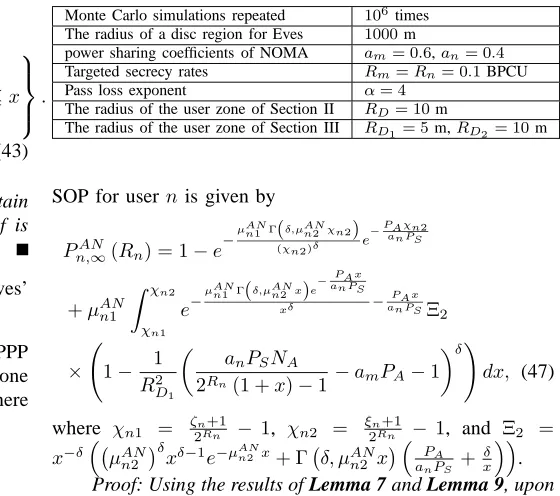
Fig. 3 plots the SOP of a single user (m-th andn-th) versus
Pm,AN∞(Rm) = 1−e
−µANκ1 Γ((δ,µANκ2 χm1)
χm1 )δ e
−PAχm1
aκPS
+ µ
AN m1b1Λ1
R2 D2−R
2 D1
Z χm2
0
e−
µANm1 Γ(δ,µANm2x)e− PAx amPS
xδ −
amPS NA
(2Rm(1+x)−1)anPS− PAx amPSΞ
1dx
+ µ
AN m1
R2 D2−R
2 D1
Z χm1
χm2 e−
µANm1 Γ(δ,µANm2x)e− PAx amPS
xδ −
PAx am PS
R2D2−t2m∗+b1e
− amPS NA
(2Rm(1+x)−1)anPS
Ξ1Λ2dx, (48)
0 10 20 30 40 50
10−4 10−3 10−2 10−1 100
ρb (dB)
Secrecy outage probability
R
D=10 m
R
D=5 m
[image:11.612.51.568.73.346.2]simulation asymptotic exact, user m exact, user n
Fig. 3: The SOP versus ρb, with ρe = 10 dB, α = 4,
λe = 10−3, M = 2, m = 1, n = 2, and rp = 10 m. The exact analytical results are calculated from (16) and (14). The asymptotic analytical results are calculated from (20) and (23).
analytical SOP of both them-th user and ofn-th user derived in (16) and (14), respectively. The asymptotic analytical SOP of both them-th andn-th users, are derived in (23) and (20), respectively. Fig. 3 confirms the close agreement between the simulation and analytical results. A specific observation is that the reduced SOP can be achieved by reducing the radius of the user zone, since a smaller user zone leads to a lower path-loss. Another observation is that the n-th user has a more steep slope than them-th user. This is due to the fact that we have m < n and them-th user as well as n-th user achieve a secrecy diversity order ofm andnrespectively, as inferred from (23) and (20).
Fig. 4 plots the SOP of the selected user pair versus the transmit SNR ρb for different path-loss factors. The exact analytical SOP curves are plotted from (18). The asymptotic analytical SOP curves are plotted from (27). It can be observed that the two kinds of dashed curves have the same slopes. By contrast, the solid curves indicate a higher secrecy outage slope, which is due to the fact that the secrecy diversity order of the user pair is determined by that of the poor one. This phenomenon is also confirmed by the insights in Remark 1.
Fig. 5 plots the SOP of the selected user pair versus
rp for different densities of the Eves. We can observe that as expected, the SOP decreases, as the radius of the Eve-exclusion zone increases. Another option for enhancing the PLS is to reduce the radius of the user zone, since it reduces the total path loss. It is also worth noting that having a lower
0 10 20 30 40 50
10−4 10−3 10−2 10−1 100
ρb (dB)
Secrecy outage probability
asymptotic simulation exact, m=2, n=3 exact, m=1, n=2 exact, m=1, n=3
α=4
[image:11.612.318.564.420.598.2]α=3
Fig. 4: The SOP of user pair versus ρb, with ρe = 10 dB,
λe= 10−3,RD = 10 m,M = 3, andrp= 10 m. The exact analytical results are calculated from (18). The asymptotic analytical results are calculated from (27).
2 4 6 8 10 12 14 16 18 20 10−4
10−3 10−2 10−1 100
r
p (m)
Secrecy outage probability
simulation exact, R
D = 5 m
exact, R
D = 10 m
λe = 10−3
λe = 10−4
Fig. 5: The SOP of user pair versus rp, with ρb = 50 dB,
ρe= 40 dB, M = 2,m = 1, n= 2, and α= 4. The exact analytical results are calculated from (18).
0.1 0.2 0.3 0.4 0.5 0.6 0.7 0.8
θ
10-4 10-3 10-2 10-1 100
Secrecy outage probability
exact, user m simulation, user m exact, user n simulation, user n
rp=10 m, 5 m, 1 m
r
[image:12.612.317.568.58.240.2]p=2 m, 3 m, 4 m
Fig. 6: The SOP versus θ, with α= 4, RD1 = 5 m, RD2 =
10 m,λe= 10−4,NA= 4,ρt= 30dB. The exact analytical results are calculated from (39) and (38).
capable of improving the secrecy performance of the scenarios considered, but this is beyond the scope of this paper.
B. Secrecy outage probability with artificial noise
From Fig. 6 to Fig. 10, we investigate the secrecy perfor-mance in the presence of AN, which correspond to the scenario considered in Section III.
Fig. 6 plots the SOP of user m and user n versus θ for different Eve-exclusion zones. The solid and dashed curves represent the analytical performance of user m and user
n, corresponding to the results derived in (39) and (38). Monte Carlo simulations are used for verifying our derivations. Fig. 6 confirms a close agreement between the simulation and analytical results. Again, a reduced SOP can be achieved by increasing the Eve-exclusion zone, which degrades the channel conditions of the Eves. Another observation is that user n
achieves a lower SOP than user m, which is explained as follows: 1) user n has better channel conditions than user
m, owing to its lower path loss; and 2) user n is capable of cancelling the interference imposed by user m using SIC techniques, while usermsuffers from the interference inflicted by user n. It is also worth noting that the SOP is not a monotonic function ofθ. This phenomenon indicates that there exists an optimal value for power allocation, which depends on the system parameters.
Fig. 7 plots the SOP of user m and user n versus λe for different number of antennas. We can observe that the SOP decreases, as the E density is reduced. This behavior is caused by the fact that a lower λe leads to having less Eves, which reduces the multiuser diversity gain, when the most detrimental E is considered. As a result, the distinctive capability of the most detrimental E is reduced and hence the secrecy performance is improved. It is also worth noting that increasing the number of antennas is capable of increasing the secrecy performance. This is due to the fact thatkhmk2in (30) andkhnk2in (32) both followGamma(NA,1)distributions,
10−4 10−3 10−2
10−4 10−3 10−2 10−1 100
λe
Secrecy outage probability
exact, user m exact, user n N
A= 2, 3, 4
[image:12.612.55.298.61.236.2]NA= 2, 3, 4
Fig. 7: The SOP versusλe, withθ= 0.8,α= 4,RD1= 5m, RD2 = 10m, ρt = 30 dB, rp = 4 m. The exact analytical
results are calculated from (39) and (38).
4 5 6 7 8 9 10
10−4 10−3 10−2 10−1
N
A
Secrecy Outage Probability
Without AN With AN
rp=10 m
rp=5 m
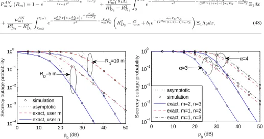
Fig. 8: The SOP of the user pair versusNA, withRD1 = 5m, RD2 = 10m,α= 3,λe= 10
−3,ρ
t= 30dB.
which is the benefit of the improved multi-antenna diversity gain.
Fig. 8 plots the SOP of the selected user pair versus NA for different path loss exponents. In this figure, the curves representing the case without AN are generated by setting
θ = 1, which means that all the power is allocated to the desired signal. In this case, the BS only uses beamforming for transmitting the desired signals and no AN is generated. The curves in the presence of AN are generated by setting
θ = 0.9. We show that the PLS can be enhanced by using AN. This behavior is caused by the fact that at the receiver side, usermand usernare only affected by the AN generated by each other; By contrast, the Eves are affected by the AN of both user m and usern. We can observe that the SOP of the selected user pair decreases, as the Eve-exclusion radius increases.
Fig. 9 plots the SOP of the selected user pair versusρtand
[image:12.612.318.564.301.476.2]0 10
20 30
40 50 0
0.5 1
10−4 10−2 100
θ ρt
Secrecy outage probability 10−3
[image:13.612.56.567.61.239.2]10−2 10−1 100
Fig. 9: SOP of the user pair versus ρt and θ, with NA = 4,
α= 4, RD1 = 5 m, RD2 = 10 m, λe = 10
−4, r
p = 10 m. The exact analytical results are calculated from (40).
ρtincreases, which is in contrast to the traditional trend, where the SOP always decreases as the transmit SNR increases. This behavior can be explained as follows. The SOP of the selected user pair is determined by user m. As ρt increases, on the one hand, the signal power of user m is increased, which improves the secrecy performance; On the other hand, user m also suffers from the interference imposed by usern
(including both the signal and AN), because whenρtincreases, the signal power of user n is also increased, which in turn degrades the secrecy performance. As a consequence, there is a tradeoff between ρt and the SOP. It is also noted that the power sharing factorθ also affect the optimal SOP associated with different values ofρt. This phenomenon indicates that it is of salient significance to select beneficial system parameters. Furthermore, optimizing the parametersρtandθis capable of further improving the SOP.
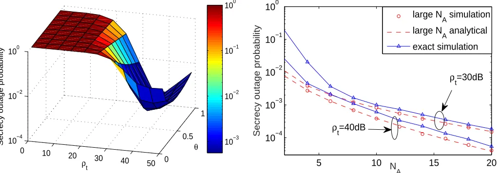
Fig. 10 plots the SOP of large antenna arrays of the selected user pair versusNAparameterized by different transmit SNRs. The dashed curves represent the analytical SOP of the selected user pair, corresponding to the results derived in (49). We observe a close agreement between the theoretical analysis and the Monte Carlo simulations, which verifies the accuracy of our derivations. We observe that as NA increases, the approximation used in our analysis approaches the exact SOP. This phenomenon indicates that the asymptotic SOP derived converges to the exact values, whenNA is a sufficiently large number.
V. CONCLUSIONS
In this paper, the secrecy performance of applying the NOMA protocol in large-scale networks was examined. Specifically, stochastic geometry based techniques were used for modeling both the locations of NOMA users and of the Eves in the networks considered. Additionally, new analytical SOP expressions were derived for characterizing the system’s secrecy performance in both single-antenna and multiple-antenna scenarios. For the single-multiple-antenna scenario, the secrecy
5 10 15 20
10−4 10−3 10−2 10−1 100
N A
Secrecy outage probability
ρt=30dB
ρt=40dB
large N
A simulation
large N
A analytical
exact simulation
Fig. 10: Large analysis for the SOP of user pair versus NA, with θ = 0.8, RD1 = 5 m, RD2 = 10 m, λe = 10
−4,
rp = 5 m. The asymptotic analytical results are calculated from (49).
diversity order of the user pair was also characterized. It was analytically demonstrated that the secrecy diversity order was determined by that one of the user pair who had a poorer channel. For the multiple-antenna scenario, it was shown that the Eves’ channel quality is independent of the number of antennas at the BS for large antenna array scenarios. Numer-ical results were also presented for validating the analysis. It was concluded that the secrecy performance can be improved both by extending the Eve-exclusion zone and by generating AN at the BS. Assuming perfect SIC operations may lead to overestimating the performance of the networks considered, hence our future research may consider investigating imperfect SIC. Optimizing the power sharing between two NOMA users is capable of further improving the secrecy performance of the networks considered, which is another promising future research direction.
APPENDIXA: PROOF OFLEMMA1
To derive the CDF ofFγB, based on (2), we can formulate FγB(x) = Pr
n
ρban|hn|2≤x o
=F|hn|2
x ρban
, (A.1)
whereF|hn|2 is the CDF of the ordered channel gain for the n-th user. Assumingy= x
ρban, and using order statistics [47]
as well as applying binary series expansion, the CDF of the ordered channels has a relationship with the unordered channels captured as follows:
F|hn|2(y) =ϕn
M−n X
p=0
M
−n p
(
−1)p
n+p
F|˜hn|2(y)
n+p
,
Based on the assumption of homogeneous PPP, and by relying on polar coordinates,F
|˜hn|2 is expressed as F
|˜hn|2(y) =
2
R2 D
Z RD
0
1−e−(1+rα)y
rdr. (A.3) However, it is challenging to arrive at an easily implemented insightful expression forF
|˜hn|2(y). Therefore, the
Gaussian-Chebyshev quadrature relationship [48] is invoked for finding an approximation of (A.3) in the following form:
F
|h˜n|2(y)≈
K X
k=0
bke−cky. (A.4)
Substituting (A.4) into (A.2) and applying the multinomial theorem, the CDF F|hn|2 of ordered channel gain is given by
F|hn|2(y)≈ϕn
M−n X
p=0
M−n p
(−1)p
n+p
×X
˜ Snp
n+p q0+· · ·+qK
K
Y
k=0
bqk
k ! e− K P k=0
qkcky
. (A.5)
Substituting y = x
ρban into (A.5), we can obtain (4). The
proof is completed.
APPENDIXB: PROOF OFLEMMA4 Based on (32), we express the CDF ofFAN
Bn as follows: FAN
Bn (x) = Pr
khnk2≤xϑ
PA
NA−1
Yn+
1 +dα n
am
= 1−
NA−1
X
p=0
ϑpxp
p! p X q=0 p q Q3 × Z D1
e−amϑx(1+d α n)
1
am
(1 +dα n)
p−q
fD1(ωn)dωn, (B.1)
where ϑ = am
anPS, Q3 =
R∞
0 e−ϑxznznqfIAN
n (zn)dzn, fIAN
n and fD1(ωn) are the PDF of I
AN
n and D1. Here
IAN
n = NPAA−1Yn, Yn = khnVmk
2
, and fD1(ωn) =
1 πR2
D1
. Upon changing to polar coordinates and applying [35, Eq. (3.381.8)], we arrive at
FAN
Bn (x) =1− δe−amϑx
R2 D1
NA−1
X
p=0
ϑpxp
p! p X q=0 p q
Q3aqm−p
×
p−q X
u=0
p−q u
γu+δ,ϑx
amR
α D1 ϑx am
u+δ . (B.2)
Finally we turn our attention on Q3. It is readily seen that IAN
n obeys the Gamma distribution in conjunction with the parameter NA−1,NPAA−1
. Then we can obtain the PDF of fIAN
n (zn) =
znNA−2e
−zn(NA−1)
PA
PA
NA−1 NA−1
Γ(NA−1)
. Apply-ing [35, Eq. (3.326.2)], we can express Q3 as Q3 =
Γ(NA−1+q)
Γ(NA−1)
PA
NA−1 NA−1
ϑx+NAPA−1NA−1+q. Upon substituting
Q3 into (B.2), we obtain the CDF of FBANn (x)as (35).
APPENDIXC: PROOF OFLEMMA5 Based on (30), we express the CDF ofFAN
Bm as FBANm (x) = Pr
γBANm ≤x
= Pr
amσ2skhmk2
anσ2s
hm h
†
n
khnk
2
+anσa2khmVnk2+ 1 +dαm
≤x . (C.1) It may be readily seen thatkhmk2obeys a Gamma distribution having the parameters of(NA,1). Hence the CDF ofkhmk2 is given by
FBANm (x) = 1−e
−x NA−1
X
p=0
xp
p!. (C.2)
Denoting Xm =
hm
h†n
khnk
2
, Ym = khmVnk 2
, based on (C.2), we can re-write (C.1) as
FBANm (x) = Pr
khmk2≤xν
ImAN +
1 +dα m
an
= 1− Z
D2
Z ∞
0 NA−1
X
p=0
νxzm+1+d
α m an p p! ×
e−νxzm−νx 1+dαm
an
fIAN
m (zm)fD2(ωm)dzmdωm, (C.3)
where ν = an
amPS, fImAN and fD2 are the PDF of I
AN m and D2, respectively. Here we have ImAN = σs2Xm+σa2Ym and fD2(ωm) =
1 πR2
D2−R 2 D1
. Applying a binary series
expansion to (C.3), we arrive at:
FAN
Bm (x) = 1−
NA−1
X
p=0
νpxp
p! p X q=0 p q Q1 × Z D2 e−νx
1+dαm an
1 +dα m
an
p−q
fD2(ωm)dωm, (C.4)
where Q1 =
R∞
0 e
−νxzmzq
mfIAN
m (zm)dzm. Note that the
distance dm is determined by the location of ωm. Then we change to polar coordinates and applying a binary series expansion again, we obtain
FAN
Bm (x) = 1−
2e−anνx R2
D2−R
2 D1
NA−1
X
p=0
νpxp
p! p X q=0 p q
×Q1
1
apn−q p−q X
u=0
p−q u
Z RD2
RD1
ruα+1e−νxPSrαdr. (C.5)
By invoking [35, Eq. (3.381.8)], we obtain
FBANm (x) = 1−
2e−anνx R2
D2−R
2 D1
NA−1
X
p=0
νpxp
p! p X q=0 p q
Q1 1
apn−q
×
p−q X
u=0
p−q u
γu+δ,νx
anR
α D2
−γu+δ,νx anR
α D1
ανx an
u+δ .