© 2019, IRJET | Impact Factor value: 7.211 | ISO 9001:2008 Certified Journal
| Page 3907
Review On Low Cost 3D Printing
Bilal Mulani
*, Abhilash Chabukswar
*, Suhas Bhalake
#, Shyam Ramnani
#*
Student, Dept. of Mechanical Engineering, P.E.S’s Modern College of Engineering, Pune-05, India
#Faculty, Dept of
Mechanical Engineering, P.E.S’s Modern College of Engineering, Pune-05, India
---Abstract -
The recent enhancement in 3D printing have proved to be more efficient over conventional manufacturing processes. Upcoming use of 3D printing technology is predominant in automotive, manufacturing, aerospace, pharmaceutical industry & healthcare. All the manufacturing processes including casting, imaging and coating, forming, machining, joining are replaced by 3D printing.This paper focuses on design and development of a low cost 3D printer. The technological advancements in extrusion materials and 3D printer’s capability have up risen the cost of manufacturing. The current situation of 3D printer is to increase precision of printers and printing of small parts at low cost. The practical 3D printer manufactured based on this paper give accuracy in microns with price lesser than the 3D printer available in market.
Key Words: Rapid Prototyping, ABS, PLA, 3D Printing, Fused Deposit Machining
1.INTRODUCTION
3D printing or additive manufacturing (AM) is one of many various processes for making a three-dimensional object of almost any shape from a 3D model or other electronic data source primarily through additive processes in which successive layers of material are laid down under computer control. A 3D printer is a type of industrial robot. 3D Printing technology was first invented by Charles Hull from 3D Systems Corp. in 1984 by the name stereo lithography. He is also started commercial rapid prototyping parallel to his development of 3D printing. Since 1984, when the first 3D printer was designed and realized by Charles Hull, the technology has evolved and these machines have become more and more useful, while their price increased thoroughly [3]. Others technology like fused deposition moulding and selective laser sintering were introduced later. In 1993 MIT changed the name from stereo-lithography to 3D Printing Technology. Three crucial products namely “Genesis” from stratasys, “Actua 2100” from 3D system, and “Z402” from Z Corporation were introduced by three different companies in 1996 [1]. In 2005 Spectrum Z510 was launched by Z Corporation as 1st 3D HD color printer [1].
3D printing refers to a wealth of techniques that fabricate an object layer by layer directly from a computer aided design (CAD) model without part-specific tooling.AM technologies can be categorized into the following seven types according to ASTM International: (1) material
extrusion (e.g. direct writing, fused deposition modelling), (2) powder bed fusion (e.g. selective laser sintering, direct metal laser sintering) (3) vat photo polymerization (e.g. stereo lithography), (4) material jetting (e.g. PolyJeT, and other inkjet printing related processes), (5) binder jetting, (6) sheet lamination (e.g. laminated object manufacturing), and (7) directed energy deposition (e.g. laser net shape engineering). Due to these versatile processes, 3D printing possesses the potential to print electronics, energy storage devices , ceramics and glasses, automotive and aircraft components, artificial ears, prosthetic limbs, meta materials and food, to name a few.
1.1 GENERAL PRINCIPLES
1.1.1
Modelling
3D modelling is a process of analysing and collecting data on the shape and appearance of an object. Firstly an exact CAD model of part to be manufacture is created using softwares like Solidworks or Catia via 3D scanner. [2]
1.1.2 Printing
Before printing the 3D CAD model is sliced using slicer software which converts the model into thin layers to gain smallest detail in model and then converted to G-code. There are several open source slicer programs exist, including, Slic3r, KISSlicer, and Cura. The main advantage of this technique is its ability to create almost any shape or geometric model.[2]
1.1.3
Finishing
Accuracy is main concern of every 3D printer manufacturer, although the product have a resolution good enough to be used in application, an end finish is must where the support material is removed and the product is given a slight finish to achieve higher-resolution process with greater precision. [2]
2. METHOD AND WORKING
2.1 Methods of Printing
2.1.1 Selective Laser Sintering
© 2019, IRJET | Impact Factor value: 7.211 | ISO 9001:2008 Certified Journal
| Page 3908
printer to create an object. Material such as plastic, metal,ceramic, glass etc. The selective laser fuses the powder by scanning the digital data on the surface of powder bed. The powder bed is lowered by thickness of one layer after completed the scanning of all cross-section and a new layer of powder is applied on the top and process is repeated until the product is completed. [1].
2.1.2 Fused Deposition Moulding
This is an additive manufacturing process use to develop prototype & production of applications. [1]. It works on additive manufacturing principle in which the material laid down layer by layer we can create an object. Here plastic filament or metal wire uses. Nozzle is heated to melt the filament and it is moved in both horizontal and vertical direction by using controlled mechanism [1].
2.1.3 Stereo lithography
In stereo lithography liquid photopolymer and ultraviolet laser are used to build the object layer by layer [1]. Exposure to the ultraviolet laser light cures and solidifies the pattern traced on the resins and joins it to the bellowed layer. After that SLA’s elevator platform moves downward by a distance equal to the thickness of single layer, typically 0.05 mm to 0.15 mm and the process is repeated until the object is completed. [1].
2.2 Working
3D Printing is an advance manufacturing process whereby laying down the material layer by layer object can be created. 3D printing is done in three steps which are follows [1]:
1. Cad design 2. Printing process 3. Finishing
Step1: In the first step design of object is created by using the computer. It requires special type of software such as cad. Any person can design an object who use that software. There are many types of softwares available, type of software is totally dependent on the requirement application.[1] You can also design the object in one software and import it to a suitable file extension like ‘.stl’ and then print the 3D object through 3D printer.
Step2: Printer slices that design into the number of layers of 0.1 mm thickness. Printer is used to create the object from that design. Print head moves according to cad model over a heat bed to print the cross-sectional data of object as in cad model. Here the scanner scan the design and the laser beams fall onto the powdered bed surface it create the cross sectional area upon that layer after completing the first layer platform lowered by 0.1 mm and the another layer of powder is to be distributed over it and the process is repeated until the object is created.
Step3: After the completion of the object extra powder removes from platform by applying vacuum pressure and
vibration to the bottom of the build chamber. Removed powder is conveyed through the system, filtered, and return to the hopper for the reuse. Next, you open the front of the machine and remove the object from platform.
3.
3D PRINTER MATERIAL
Following are the materials which can be used for printing and their properties:
3.1 Acrylonitrile Butadiene Styrene [ABS] : One of the most widely used material since the inception of 3D printing. This material is very durable, slightly flexible, and lightweight and can be easily extruded, which makes it perfect for 3D printing [3]
Technical Specifications: • Density- 1-1.4 gm/cm3 • Dielectric constant- 3.1 to 3.2 • Elastic modulus- 2 to 2.6 GPa • Elongation at break- 3.5 to 50% • Flexural modulus- 2.1 to 7.6 GPa • Flexural strength- 72 to 97 MPa
• Strength to weight ratio- 37 to 79 kN-m/kg • Tensile strength: 37 to 110 MPa
• Thermal expansion- 81 to 95 µm/m-K
Material Properties of Acrylonitrile Butadiene Styrene [ABS]
• Temperature - 225°C • Flow Tweak - 0.93
• Bed Temperature - 90°C [3]
3.2 Poly Lactic Acid [PLA]:
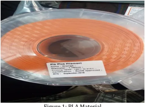
[image:2.595.315.554.583.758.2]Polylactic Acid(PLA) (is derived from corn and is biodegradable) is another well-spread material among 3D printing enthusiasts. It is a biodegradable thermoplastic that is derived from renewable resources. PLA glass transition temperature is between 60 – 65 ° C, so PLA together with ABS could be some good options for any of your projects. [3]
© 2019, IRJET | Impact Factor value: 7.211 | ISO 9001:2008 Certified Journal
| Page 3909
Technical Specifications• Density - 1.3 g/cm³ (81 lb/ft³)
• Elastic (Young's, Tensile) Modulus - 2.0 to 2.6 GPa (0.29 to 0.38 x 10³ psi)
• Elongation at Break - 6.0 %
• Glass Transition Temperature - 60 °C (140 °F)
• Heat Deflection Temperature At 455 kPa (66 psi) - 65 °C (150 °F)
• Melting Onset (Solidus) - 160 °C (320 °F)
• Shear Modulus- 2.4 GPa (0.35 x 10 psi)
• Specific Heat Capacity - 1800 J/kg-K
• Strength to Weight Ratio - 38 kN-m/kg
• Thermal Conductivity - 0.13 W/m-K
• Thermal Diffusivity - 0.056
Material Properties of Poly Lactic Acid [PLA] • Temperature - 180°C
• Flow Tweak - 0.95 • Bed Temperature - 60°C
4.
PART SIGNIFICANCE
The background contains research and the prerequisite knowledge needed to understand the mechanical and electronic component justifications and respective parts.
4.1 Stepper Motors
Stepper motors are DC motors that have multiple coils allowing them to move in small increments. These coils are “organized in groups called ‘phases’. By energizing each phase in sequence, the motor will rotate, one step at a time.” [4]. by having a computer control these movements, they can be very precise. They are best used for positioning, speed control, and low speed torque. Stepper motors come in many different shapes and sizes [4]. Choosing the correct stepper motor for a desired task is greatly dependent on those characteristics.
4.2 Power Supply
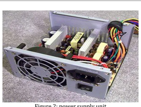
[image:3.595.319.549.82.256.2]A 3D printer requires electricity in order to operate its motors, control boards, and heating elements. The most readily available source of electricity is a standard wall outlet. However, the 110-120V AC power cannot directly power the 3D printer. The components require lower-voltage DC power to operate, and would quickly burn out from the high voltage from the outlet. Therefore, a power supply unit (PSU) is necessary to convert the 110-120V AC to DC voltage, typically 12-24 V, which can be used to power the printer. There are two main designs for a PSU circuit: linear power supply or switch-mode power supply. [5]. Most power supplies that are applicable for use in a 3D printer are switch-mode power supplies.
Figure 2: power supply unit
4.3
Control Board
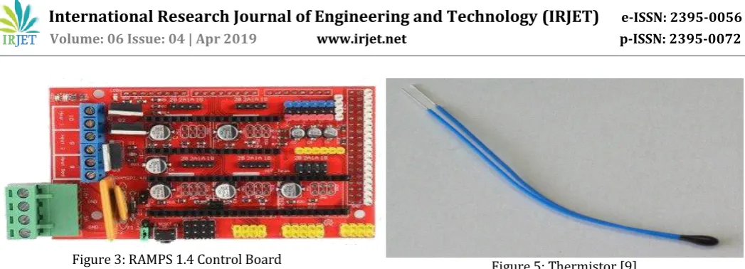
[image:3.595.308.573.378.602.2]The Control board is made up of two components: a microcontroller and a circuit board. These components can be either combined into one board, or be separate units attached to each other. Both work simultaneously to control and distribute power to all other components listed below. It is referred to as the brains and the central nervous system of the printer.
Table -1: Different Control boards
© 2019, IRJET | Impact Factor value: 7.211 | ISO 9001:2008 Certified Journal
| Page 3910
Figure 3: RAMPS 1.4 Control Board4.4 Drivers
[image:4.595.40.308.410.479.2]The stepper motors of a 3D printer need to be precisely controlled to produce a good quality print. One of the components responsible for this function is the stepper motor driver. A stepper motor driver is a chip that controls the power flow to the stepper motor so that the motor can be precisely positioned. The drivers receive a signal from the microcontroller that specifies how much the stepper motor needs to move. Typically, the microcontroller does not supply the power to the motor directly, since the microcontroller cannot provide enough power to drive the stepper motor[7]. Using a driver, the microcontroller can control the speed and position of the stepper motors while powering the motors directly from the power supply.
Figure 4: Drivers
4.5 Endstops
Endstops are the components responsible for ensuring that the print head stops moving in a given direction when it has reached the end of the 3D printers rail system.[8]This sort of sensing is easily achieved either mechanically, magnetically, or optically depending on the application. 3D printers like the one featured in this report typically use either optical or mechanical switches, since they are more accurate at lower prices than the magnetic options.
4.6 Thermistors
An inherent part of a 3D printing operation is the controlled heating of extruders to melt the print medium. This necessitates temperature feedback from the print head to the control board. This is done using a “thermistor: an electrical resistor making use of a semiconductor whose resistance varies sharply in a known manner with the temperature”.
The higher the temperature of the semiconductor, the less energy is required move electrons, since the entire material is closer to the activation energy needed to move electrons in a polar direction.
Figure 5: Thermistor [9]
4.7
Extruders
The extruder on a FDM 3D printer is an integral component of its functionality. The extruder is responsible for moving the correct amount of material through a heating element for the printing of layers. Extruders contain a stepper motor that moves the material through a drive and idle gear that work together to push the filament towards the heated end.
The two main types of extruders used in 3D printing are Bowden and direct drive extruders, as shown in Figure 3.6. The main difference between these is the process in which the material is fed into the printing end of the carriage. In Bowden extruders, filament is fed through a Bowden tube into the printing end of the carriage [10]. The downside to the Bowden extruder is increased friction resulting in difficulty creating flexible filaments which is caused from the long travel distance of the filament [10]. In direct drive extruders, the extruder is directly attached to the printing end.
4.8
Heated Beds
[image:4.595.306.581.582.750.2]Heated beds are a key part of most 3D printers as they help to improve print quality. Printing onto a heated bed helps to prevent warping during the print process by keeping the part warm during printing which allows for more predictable and uniform shrinking of the plastic. There are a few materials that can be printed without using a heated bed such as PLA, however, parts made with this material can always benefit from a heated bed.
© 2019, IRJET | Impact Factor value: 7.211 | ISO 9001:2008 Certified Journal
| Page 3911
5.
ADVANTAGES
Time-to-Market:
Cheaper process than any other process No skilled person required
Surface Quality
Build your Imagination Square Holes? No Problem Less wastage of raw material
6.
DISADVANTAGES
Cost of raw material is high [3].
3D Printer is also expensive.
It takes more time to create a single object.7. CONCLUSIONS
3D printing is the method of converting 3D CAD design into the actual replica. After the few years of launch of affordable 3D printer we will see the machine in every home, if they want to make any toy or even utensils using 3d CAD file instead of the product. In medical field 3D printer are making human organs for the need of peoples. Supremacy of 3D printer is vast and efficient therefore it is most preferable and reliable technology. 3D Printing technology could revolutionize the world. Development in 3D printing technology can significantly change and improve the way we manufacture products and produce goods worldwide. Scientists are studying various considerable working parameter like printing method, temperature of liquefaction of ink material and also its solidification along with its time requirement, application has proved that ABS is best suitable as printing ink in various application. On the top of this, a visionary concept of using actual iron materials like stainless steel or aluminium as ink material is being studied and is the topic of development of 3D printing technology.
REFERENCES
[1] Swati B. Nale, Prof. A. G. Kalbande. A Review on 3D Printing
Technology.
[2] Chandrashekhar kalnad. A review on 3D Printing
[3] Vinod G. Gokhare, Dr. D. N. Raut, Dr. D. K. Shinde. A Review
paper on 3D-Printing Aspects and Various Processes Used in the 3D-Printing.
[4] Earl, Bill. What is a Stepper Motor? 23 November 2015. 22
April 2017. <https://learn.adafruit.com/all-about-stepper-motors/what-is-a-stepper-motor>.
[5] Coates, Eric. Switched Mode Power Supply. 17 February 2017.
22 April 2017.
http://www.learnabout-electronics.org/PSU/psu30.php
[6] Image of ramps 1.4:
https://robu.in/product/ramps-1-4-3d-printer-controller-5pcs-4988-driver-heat-sink-kit/
[7] Future Electronics. What is a Motor Driver? n.d. 22 April
2017.:-http://www.futureelectronics.com/en/drivers/motor-driver.aspx .
[8] RepRap. Mechanical Endstop. 27 December 2014. 23 April
2017:-http://reprap.org/wiki/Mechanical_Endstop .
[9] Encyclopedia Britannica. Thermistor. 8 September 2009. 23
April 2017:-
https://www.britannica.com/technology/thermistor
[10] Landry, T. (2017). Extruders 101: A crash course on an
essential component of your 3D printer | MatterHackers. https://www.matterhackers.com/articles/extruders-101:-a-crash-course-on-an-essential-component-of-your-3d-printer
[11] Image from site Hunter valley hotels:
http://www.huntervalleyhotels.co/block-diagram-3d-printer.html
BIOGRAPHIES
DESCRIPTION:
BILAL MUSTAQ MULANI D.O.B. - 07/02/1997 STUDENT ,
DEPT. OF MECHANICAL ENGINEERING,
P.E.S’s MODERN COLLEGE OF ENGINEERING,
PUNE-05
DESCRIPTION: ABHILASH ATUL CHABUKSWAR D.O.B. - 21/06/1997 STUDENT ,
DEPT. OF MECHANICAL ENGINEERING,
P.E.S’s MODERN COLLEGE OF ENGINEERING,
PUNE-05
DESCRIPTION: SUHAS BHALAKE ASSISTANT PROFESSOR , DEPT. OF MECHANICAL ENGINEERING,
P.E.S’s MODERN COLLEGE OF ENGINEERING,
PUNE-05
DESCRIPTION: SHYAM RAMNANI ASSISTANT PROFESSOR , DEPT. OF MECHANICAL ENGINEERING,
P.E.S’s MODERN COLLEGE OF ENGINEERING,