Change Management
within SysML Requirements Models
David ten Hove
Master's thesis
University of Twente
Faculty of Electrical Engineering, Mathematics and Computer Science
Department of Computer Science
Software Engineering Group
June 24
th2010
Graduation committee:
University of Twente
- dr. ir. Klaas van den Berg
- dr. Ivan Kurtev
- Arda Goknil, Msc.
@Portunity
Abstract
The need to properly manage change within software projects is very real. Not the least of the consequences of unmanaged or poorly managed change is de-creased software maintainability. As changes in higher abstraction levels always propagate to the lower levels, it is important to manage change not only in code and design, but in requirements documents and requirements models as well.
We propose a method for managing changes within requirements. This method is based on keeping requirements models (expressed in SysML) in sync with what the stakeholders want, also known as the application domain. It focusses on determining which model elements are impacted, how they are im-pacted and how the impact has to be dealt with. Changes in the application domain are identified, a model element is designated to be affected and from this, the complete impact of the change on the model is calculated using the require-ment relations as trace links. This calculation is performed using propagation rules, which are derived from the formalization of requirements, requirement relations and applicatoin domain changes we have created.
A running example is used to show the usage and practicality of the method. Some application domain changes of varying complexity are applied to an ex-ample requirements model to illustrate how the method performs in practice and how useful it can be. Furthermore, we provide tool support in the form of a prototype. This prototype, an extension of the commercial tool Blueprint, illustrates the user interactions in the process.
The method we propose has some limitations. First of all, it is partially automated. The experience and knowledge of a requirements engineer is still required for proper use. Second, it is based upon a very specific interpretation of the requirements relations in use. As there are many other viable interpretations possible, this method may not be applicable to every software project without adaptation. Apart from these limitations however, we believe the method does provide meaningful support to change management within software require-ments models.
Acknowledgements
I would like to thank the people who have helped me during this research project. First of all, my supervisors Arda, Klaas and Ivan for guiding me through the project by giving constructive feedback. The brainstorm sessions and dis-cussions were very helpful and inspiring. Special thanks to Arda who, with his own work, provided me with a very good starting point for my research.
Also, I would like to thank Koos from @-portunity for giving me the possi-bility to apply my approach to an existing tool, rather than having to build my own from scratch.
My fellow students in room 5066 cannot go unmentioned here. They were always in for a laugh and willing to share their insights. Because of them, the Zilverling was never a dull place for me to work.
Finally, I want to thank my family. They never gave up on me and always supported me as best they could. I want to give special thanks to my parents, who always supported me and took care of me when my health was at its worst. Without their help, love and support I never would have been able to finish this work.
David ten Hove, June 2010, Enschede
Table of Contents
Abstract iii
Acknowledgements v
1 Introduction 1
1.1 Context . . . 1
1.2 Problem statement . . . 3
1.3 Approach . . . 4
1.4 Overview . . . 5
2 Basic concepts 7 2.1 MOF . . . 7
2.1.1 OMG four layered architecture . . . 7
2.1.2 Purpose of MOF . . . 8
2.2 UML . . . 8
2.2.1 Modeling using UML . . . 8
2.2.2 Customizing UML . . . 9
2.3 Using OCL with UML . . . 9
2.4 SysML . . . 10
2.4.1 SysML diagrams . . . 11
2.4.2 Modeling requirements in SysML . . . 11
2.5 Model Driven Engineering . . . 13
2.6 Change Management . . . 13
2.7 Summary . . . 13
3 Classification of changes 15 3.1 Domain . . . 15
3.2 Domain change . . . 15
3.3 Model . . . 16
3.4 Model Change . . . 16
3.5 External inconsistency . . . 17
3.6 Internal Inconsistency . . . 17
3.7 Requirement parts and details . . . 17
3.8 Summary . . . 18
4 Impact Analysis Process 19 4.1 Process . . . 19
4.2 Relations between terms . . . 20
4.3 External inconsistency propagation . . . 21
4.4 Summary . . . 24
5.2 Relevant SysML model elements . . . 25
5.3 Formalizations . . . 26
5.3.1 Requirement . . . 26
5.3.2 Formalization of TracedTo . . . 27
5.3.3 Formalization of DerivedFrom . . . 28
5.3.4 Formalization of ComposedBy . . . 28
5.3.5 Formalization of CopyOf . . . 28
5.4 Domain change case analysis . . . 29
5.4.1 New requirement added . . . 29
5.4.2 Existing requirement removed . . . 29
5.4.3 Requirement made more specific . . . 30
5.4.4 Requirement made more abstract . . . 30
5.4.5 Part removed from requirement . . . 30
5.4.6 New part added to requirement . . . 30
5.5 Propagation rule derivation . . . 31
5.5.1 New part added to requirement . . . 31
5.5.2 Requirement made more abstract . . . 32
5.6 Discussion of formalization . . . 33
5.6.1 Using predicates and systems . . . 34
5.6.2 Using systems only . . . 34
5.7 Summary . . . 34
6 Example process usage 35 6.1 Example Model . . . 35
6.2 Example changes . . . 36
6.2.1 Remove setting visibility of archived items . . . 37
6.2.2 Remove student team support . . . 38
6.2.3 Add support for removing grades . . . 39
6.3 Summary . . . 40
7 Tool Support 43 7.1 Blueprint . . . 43
7.1.1 Blueprint capabilities . . . 43
7.1.2 Blueprint data structure . . . 44
7.2 Solution location . . . 44
7.3 Plugin development . . . 45
7.4 Plugin architecture . . . 46
7.4.1 AbstractChangeImpactAnalysisAction . . . 46
7.4.2 PartMadeMoreSpecific . . . 46
7.4.3 PartMadeMoreAbstract . . . 47
7.4.4 PartAddedToReq . . . 47
7.4.5 PartRemovedFromReq . . . 47
7.4.6 ReqRemoved . . . 47
7.4.7 ModelQuerier . . . 47
7.4.8 OCLModelQuerier . . . 47
7.4.9 RulesManager . . . 47
7.4.10 PropagationChooser . . . 48
7.4.12 ChangeImpactListener . . . 48
7.4.13 StdOutListener . . . 48
7.4.14 AbstractUMIModelCommandAction . . . 48
7.5 Example usage . . . 49
7.5.1 Example model . . . 49
7.5.2 Usage . . . 49
7.6 Summary . . . 50
8 Conclusion 51 8.1 Classification of changes . . . 51
8.2 Determining and resolving impact . . . 52
8.2.1 Process workings . . . 53
8.2.2 Formalization and derivation . . . 53
8.3 Tool support . . . 54
8.4 Evaluation . . . 54
8.4.1 Choice of metamodel . . . 54
8.4.2 Formalization . . . 54
8.4.3 Change Impact Analysis Process . . . 55
8.4.4 Final remarks and future work . . . 55
A Test Plan 57 A.1 Basic tests . . . 57
A.1.1 Testing domain change to external inconsistency to model change mappings . . . 57
A.1.2 Testing the derivement relation . . . 58
A.1.3 Testing composition relation . . . 60
A.1.4 Testing copy relation . . . 61
B Example model 63 B.1 Example model . . . 63
1
Introduction
1.1
Context
Change management has always been a vital process within software develop-ment projects. Traditionally, it is performed more or less ad hoc. First, a change is requested, for example because a stakeholder presents a change in his or her interests. A software engineer uses his experience and knowledge of the software to then identify which software artifacts are affected by the change, how they are affected, and how they should be updated.
In smaller software projects, this approach may be prudent. However, when software projects get larger and more complex this may lead to serious issues. Studies have shown that when predicting change impact, software engineers tend to severely underestimate not only how many artifacts are impacted, but also how bad the impact will be for those artifacts [LS98].
[RI06] depicts the current status of requirement change management process models. It describes a multitude of activities within change management process such as planning for change, cost benefit analysis and submission of modification report. Their focus is on the organizational aspect of change management.
A lot of research has been performed in the field of change management, focussing on the effects of different methods (or lack thereof) and on improving these methods. For example, [JL04] identifies four common impact analysis strategies:
Analyzing traceability or dependency information
Utilizing slicing techniques
Consulting design specifications and other documentation
Interviewing knowledgeable developers
The first two of these methods are automatable processes, the last two are manual.
[BLOS06] defines an automated change impact analysis process in the con-text of UML models. It focusses on keeping several UML models of a single software system in sync with each other by propagating changes made to one model to related models. The process consists of four subprocesses:
Verify the consistency of changed diagrams. In other words, check if the model is consistent with itself
Automatically detect and classify changes. Classify according to a prede-termined change taxonomy
Perform impact analysis. Based on impact analysis rules, using the change taxonomy
Prioritize the results of impact analysis.
Several other approaches have been developed. Although the previously mentioned approaches consider other software architects as well, most approaches are based on change impact analsysis to and from software code. These ap-proaches certainly have their merits, but in larger software systems it is neces-sary to properly manage change in higher abstraction levels, such as the design and the requirements, as well.
One approach which focusses mostly on requirements is [GKvdB09]. This research defines its own metamodel of requirements and requirements relations with a well-defined mathematical basis. They apply a distinction between changes based on the notion of the application domain1. The domain is that which the stakeholders have an interest in, and that which the model has to represent. The types of changes are:
A change which is necessitated by a change to the domain. These affect the functional and non-functional properties of the required system.
A change which is not related to a change in the domain. These do not affect the functional or non-functional properties of the required system. They are usually refactoring changes.
When a change is made of either type, the requirements relations are used as traces to determine if the change needs to be propagated to other model elements. This propagation is performed by use of propagation rules, which are based on the mathematical definition of requirement, requirement relations and changes. This work has provided us with a good starting point for our research and excellent comparison material, even though there are several elements which make the two researches very much distinct.
The main distinctions between our work and [GKvdB09] are that we use a different modeling basis and that we do not support managing changes which do not stem from changes in the domain.
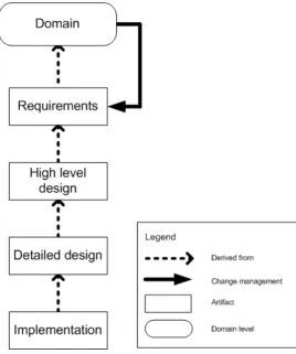
As in [GKvdB09], we consider only change management within requirements models, as shown in figure 1.1. The boxes in this picture (apart from the domain) show the levels of software development with artifacts. The artifacts in the requirements level can be extracted from the domain. The artifacts in the high level design can be derived from the requirements, and so on. When the
1.2. Problem statement 3
[image:13.595.136.405.183.505.2]requirements have been derived from the domain and later on a change occurs in the domain, the requirements may need updating. This is what we intend to address and it is shown in the figure by the solid line. Note that this kind of propagation holds for any two layers, and that this is also transitive.
Figure 1.1: Abstraction levels in software development
Current tool support for change management within requirements models is limited. One tool which is widely used is Rational RequisitePro, created by IBM [Req]. Amongst other things, this tool allows users to specify requirements and to specify which requirements are related to one another. It is not possible however, to specify exactly how requirements are related, which severely limits the change management possibilities.
1.2
Problem statement
Change management can be performed on different abstraction levels, such as the design or the code. The effect of a change can easily span over sev-eral levels, and in perfect change management all levels would be considered. However, since this would be a monumental task, we consider only the levels of domain and requirements. There are several ways in which the requirements can be represented. We use a subset of the SysML metamodel developed by OMG, because it contains a number of predefined requirements relations. See also [OMG07a].
The largest issue with the current approaches, is that the relations lack semantics. This causes the impact analysis to be very imprecise in that there will almost always be false positives. In many cases, a change to a single requirement will affect a very large part, if not all of the model. This is known as the impact explosion.
Our main research question is the following: Given a change in the do-main, how does the SysML requirements model have to be updated in order to correctly reflect the domain?
In order to answer this question, we first have to determine the impact of the change. This involves determining which model elements are impacted, and how.
Determining which elements are impacted is done by examining the type of the domain change and the relations between the requirements in the model. So, in order to perform this step correctly, we need to classify the domain changes and formalize them along with the requirement and the requirement relations.
Determining how elements are impacted also involves determining the kinds of impact a domain change can have on the model. These impacts will also need to be classified. As a final step, the model needs to be updated according to the information gathered in the previous two steps. In order to update the model, we need to classify model changes and relate them to types of impact.
Our overall goal is to provide support for change impact analysis within software projects. The research questions are divided into three categories:
1 Classification
1.1 What are the types of domain changes
1.2 What are the types of impact of domain changes on model elements
2 Determining and resolving impact
2.1 How can we determine which model elements are impacted
2.2 How can we determine the type of impact on these elements
2.3 How can we solve the impact of domain changes on model elements
3 Tool support
3.1 How can we use tools to support change management
1.3
Approach
1.4. Overview 5
management methods. We will also look at existing requirements management tools. A running example will be used to determine the viability of the process and a prototype will be constructed to examine tool support possibilities.
1.4
Overview
The document is divided into the following parts:
Chapter 1. Introduction
Chapter 2. Basic concepts.
Chapter 3. Definitions and classifications.
Chapter 4 and 5. Impact analysis process and mathematical foundation.
Chapter 6. Example usage of impact analysis process.
Chapter 7. Tool support.
Chapter 8. Evaluation and conclusion
2
Basic concepts
This chapter describes some the basic concepts we use in our thesis. These include various modeling standards, model driven engineering and change man-agement.
2.1
MOF
The MetaObject Facility (or MOF) is a standard adopted by OMG which defines a metamodel that is currently being employed by a number of widely used technologies, such as UML and SysML, which will both be described later in this chapter. It is defined in [OMG06].
2.1.1
OMG four layered architecture
MOF is at the top of the OMG four-layered architecture, shown in figure 2.1.
M0is the data layer, such as the program being executed.
M1is the model layer, which contains models as built by system engineers. It is this model the data in layer M0 conforms to.
M2is the metamodel layer, which contains metamodels such as UML and SysML. A systems engineer applies this metamodel to create models of layer M1.
M3 is the meta-metamodel layer, which contains the metamodels of the metamodels, including MOF. In the OMG four layered architecture, there is no higher level. The metamodel of MOF is MOF. That is, MOF is defined in itself.
Figure 2.1: OMG architectural layers. Based on [OMG02]
2.1.2
Purpose of MOF
The main purpose of MOF is to provide interoperability of models. A model which conforms to MOF can be imported, exported and edited by any tool with the possibilities. If no such higher-level metamodel would exist, tools would have to be customized for every (meta)model it would want to work with. However, it is not only tools which benefit from MOF, but also technologies. The Object Constraint Language for example, which is explained later in this chapter, allows developers to apply constraints to any model which conforms to MOF.
2.2
UML
2.2.1
Modeling using UML
The Unified Modeling Language (UML) is a language for specifying, construct-ing and documentconstruct-ing object-oriented software systems and is defined in [OMG07b]. It is a general-purpose modeling language that can be used with all major object and component methods, and that can be applied to all implementation plat-forms, such as J2EE and .NET. UML is also a visual language, which means it is specified in diagrams. UML specifies several diagram types, the most commonly used including:
2.3. Using OCL with UML 9
the classes, attributes, operations and the relations between classes.
Use case diagrams. Describe the functionality of a system by showing the actors, the goals and the relations between these.
Sequence diagrams. Describe the workings of a system by showing the objects and the messages exchanged between them.
These diagrams, among with many others in UML, are used by software devel-opers throughout the world to specify and document their software systems. As stated before, UML uses MOF as its metamodel.
2.2.2
Customizing UML
[image:19.595.185.357.401.613.2]In many cases, it is desirable to customize UML to a certain domain. Cus-tomization is possible using profiles, which define an extension to any reference metamodel (such as UML). The only requirement for the reference metamodel is that it conforms to MOF. Each profile contains any number of stereotypes that extend an already existing element of the metamodel, e.g. a metaclass or an actor. Stereotypes have meta-attributes called tagged values. When creating a model which conforms to a metamodel with a specific profile applied to it, the elements with custom stereotypes have to have a concrete value for each tagged value of that stereotype. Figure 2.2 shows how MOF, UML and UML profiles relate to each other.
Figure 2.2: MOF, UML and UML profiles
2.3
Using OCL with UML
adapted by OMG so that it can now be applied to any MOF-based model. These expressions typically specify invariant conditions that have to hold for the system being modeled, but can also be used to define pre- and postcondi-tions. OCL is necessary for these constraints as there is often no other way in these models to describe them formally. Of course, natural language can be applied, but this requires the constraints to be checked manually, as opposed to automatically.
The constraints can range from simple to very complex. As a simple example, consider a class Person with a single attribute: age. A sensible constraint would be to ensure that the age of a person is always greater than or equal to zero. In OCL, it could look like this:
context P e r s o n inv a g e C o n s t r a i n t : s e l f . a g e >= 0
The constraint first specifies the context as the class int Person. Next, the type is set: invfor invariant. Other possible types arepreand post. It then names itself ageConstraint. The second line specifies that the attribute reached with self .age has to have a value higher than or equal to zero. Note that self . may be omitted in this case.
2.4
SysML
[image:20.595.215.433.526.686.2]SysML is a general-purpose modeling language for systems engineering that is designed to provide simple but powerful constructs for modeling a wide range of systems engineering problems and is defined in [OMG07a]. It supports modeling and specifying requirements, structure, behavior, allocations and constraints of systems. In the same way the Object Management Group has introduced UML in an attempt to standardize software modeling, SysML is intended to standardize modeling and engineering of almost any kind of system. SysML reuses a subset of UML 2, called Uml4SysML. Figure 2.3 shows how Uml and SysML relate to each other.
2.4. SysML 11
The region marked ”SysML Extensions to UML” indicates the new modeling constructs for SysML which do not have a counterpart in UML, or replace UML constructs. Note that, as the figure shows, there is also a part of UML which is not used by SysML. The fact that SysML reuses a large part of UML makes it easier for engineers who have experience with UML to adopt the new language.
2.4.1
SysML diagrams
[image:21.595.120.426.273.403.2]SysML is a graphical language, like UML. It reuses a number of the diagrams specified in UML, but also introduces two new ones. Figure 2.4 shows the diagrams in SysML.
Figure 2.4: Diagrams in SysML. [OMG07a]
The two diagrams introduced are requirement and parametric. A parametric diagram is defined as a restricted form of internal block diagram. I t describes constraints, constraint parameters and constraint blocks. These constraints limit the physical properties of a system and can be used to identify critical performance parameters and their relations to other parameters. Parametric diagrams can be used to support trade-off analysis, since the factors in the applicable equations are objectively and formally presented.
A requirement diagram displays requirements, packages, other classifiers, test cases and rationale, along with their relations. It is used to structure requirements and to link them to other design elements within SysML.
2.4.2
Modeling requirements in SysML
Compositerelations allow a requirement to contain sub-requirements
Copyrelations define links between a master requirement and a copy of it, known as a slave requirement
Deriverelations allow one requirement to be derived from another
Satisfyrelations define a model element as satisfying a requirement
Verifyrelations define a test case as verifying a requirement
Refine relations define a model element or set thereof as refining a re-quirement
Trace relations define a generic relation between a requirement and any other model element
Acompositerequirement can contain subrequirements to specify hierarchy. This is done using the UML namespace containment mechanism. The relation allows complex requirements to be decomposed into simpler ones to make things more concrete, or to apply abstraction to the model. Of course, subrequirements themselves may be composed of additional child requirements, and so on.
Copy relations specify slave and master requirements. SysML defines slave requirements as requirements whose text property is a read-only copy of the text property of its master requirement, where the master requirement may be declared in a completely different namespace. This means that the master requirement could be defined in a different project altogether, and without this relation it may be impossible to refer to it. The slave requirements cannot be changed, but when the master requirement is changed, so are all its slaves. This has been included in the SysML specifications in order to provide better support for requirement reuse, something which the designers of SysML discovered to be very important.
Another relation specified is thederiverequirement, which relates a derived requirement to its source requirement. In other words, a client requirement can be derived from the supplier requirement. This typically involves analysis to determine the multiple derived requirements that support a source requirement. This relation is commonly used to define multiple layers of a system hierarchy. Thesatisfyrelation describes how a design or implementation model sat-isfies one or more requirements. The satisfying element can be almost anything in SysML.
The verify relation defines how a test case verifies a requirement. Test cases in SysML are intended to be used as a general mechanism to represent any of the standard verification methods for inspection, analysis, demonstration or test. The verdict of a test case can be used to represent the verification result. Using the refine relation it is possible to describe how a model element can be applied to further refine a requirement, where the model element can be almost anything in SysML.
2.5. Model Driven Engineering 13
2.5
Model Driven Engineering
Model driven engineering means modeling not with standard classes and inter-faces such as those found in UML, but with the components relevant to a certain domain. For example, one could model students, teachers and courses. In order to do this, a suitable Domain Specific Language needs to be defined.
There is a number of advantages to applying this kind of modeling. With conventional modeling, the modelers had to be experts both in the field of technology and in the field of the specific domain. Possibly the biggest advantage is that this is no longer necessary. In the ideal case, an expert on a domain who has no technical knowledge whatsoever can model the things he knows, and the engineers can then implement the software system based on this model. Currently, there is a gap between the state of the practice and the states of the art regarding model driven engineering.
2.6
Change Management
Managing changes in the context of software engineering is a prerequisite for high quality software management. This includes changes at every level of the development, whether it be the requirements, the architectural design or the implementation. In general, the higher the level at which change occurs, the bigger the impact. One aspect of change management is change impact analysis. This section describes change impact analysis at the design level. For simple, small models, change impact analysis occurs by user intuition and experience. However, in larger, more complex models, the need for an automated change impact analysis is very real.
[image:23.595.126.424.501.613.2][KS98] describes a change management process. A simple overview of this process as described there is shown in figure 2.5. This assignment fits in the gen-eral process as three elements: ”Find affected requirements”, ”Find dependent requirements”, and ”Propose changes”.
Figure 2.5: Change management process. [KS98]
2.7
Summary
being used by several other standards, including UML and SysML. UML is a visual language for specifying, constructing and documenting object-oriented software systems. OCL makes it possible to define expressions on MOF-based models. SysML is a general-purpose modeling language for systems engineering that is designed to provide simple but powerful constructs for modeling a wide range of system engineering problems.
3
Classification of changes
In this chapter we introduce the terms we use in the change impact analysis process and classify domain changes, model changes and external inconsisten-cies.
3.1
Domain
Before we can begin to model anything, we need a name for it: The application domain (which we refer to simply as the domain). The concept of domain is described in [vL09], although it is not labeled there as such. The domain is what the stakeholders want to be modelled, and possibly implemented as well. These stakeholders have their own requirements, each specifying a functional or non-functional need.
Domain: The part of reality that needs to be modelled, viewed through the requirements it sets for the resulting system.
Changes in the domain can occur in several ways. For example, a stake-holders mind could change or the environment could change. Changes to the environment can be economical, jurisdictional etc.
3.2
Domain change
Below is a classification of types of change to a domain.
1 New requirement added
2 Existing requirement removed
3 Requirement made more specific
4 Requirement made more abstract
5 Part removed from requirement
6 New part added to requirement
This classification is based on a case analysis, described in section 5.4. It is not elaborated upon any further in this section, as it is entirely based on mathematical formalization.
3.3
Model
The term model has an intuitive meaning to most software engineers. We base our definition from [SSB93] and [FHL+98]. It is that which reflects the reality
(or in this case, domain) as well as possible, or that which needs to be built. There are three properties of the concept of a model which are very important. The first is that it is an abstraction of reality. Certain details are deliberately omitted. The second is that a model serves a purpose. The purpose of a model is the guiding principle in deciding which parts of reality to include. The third property is that a model is always associated to a domain. Models are expressed in modeling languages.
Model: A model represents a part of the reality called the domain and is expressed in a modeling language. A model provides knowledge for a certain purpose that can be interpreted in terms of the domain.
3.4
Model Change
Below is a classification of types of change to a model.
1 Requirement is added
2 Requirement is removed
3 Detail added to requirement description
4 Detail removed from requirement description
5 Part removed from requirement description
6 Part added to requirement description
7 Relation is removed
8 Relation is added
3.5. External inconsistency 17
3.5
External inconsistency
The change impact analysis approach is focused on keeping the model synchro-nized with the domain. External inconsistencies define a difference between the model and the domain. They can be caused by a domain change. If so, the type of domain change determines the type of external inconsistency. They are also always related to one or more model elements, or the lack of thereof.
External Inconsistency: An external inconsistency defines which model ele-ments (or lack thereof) in a model do not conform to the domain.
Below is a classification of external inconsistencies, based on the classification of domain changes.
1 Requirement in the domain, but absent in the model
2 Requirement not in the domain, but present in the model
3 Requirement in the model less specific than in the domain
4 Requirement in the model more specific than in the domain
5 Requirement in the model has more parts than in the domain
6 Requirement in the model has less parts than in the domain
3.6
Internal Inconsistency
While external inconsistencies define a difference between the model and the domain, internal inconsistencies define a conflict within the model itself. Inter-nal inconsistencies are caused by applying relations in a way that violates its formalization. Chapter 5 contains this formalization.
Internal inconsistency: A violation of relation constraints within a model.
3.7
Requirement parts and details
3.8
Summary
In this chapter we defined several terms. We defined the domain as that in which the stakeholders have an interest in and therefor has to be modeled. We defined the model as that which reflects the domain. External inconsistencies are defined as inconsistencies between the model and the domain and internal inconsistencies as inconsistencies within the model itself.
Requirements are defined as sets of parts, which can have details applied to them. For any given implementation, the parts of a requirement can be evaluated to true or false, taking the details in consideration. Details limit the implementations which satisfy a part and do not have any meaning on their own. We also classified the following: Domain change, model change and external inconsistency.
4
Impact Analysis Process
This chapter describes the change impact analysis process. It shows the relevant SysML relations and the tables containing the rules for external inconsistency propagation and the rules for mapping domain changes to external inconsisten-cies to model changes.
4.1
Process
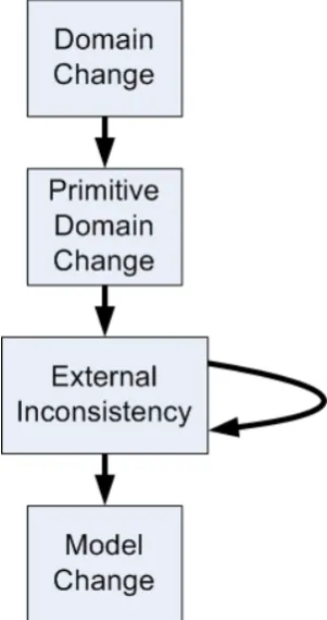
The change impact analysis process starts with the identification of a domain change, which should be performed by a requirements engineer. The require-ments engineer then splits the domain change up into one or more primitive domain changes. For each of these primitive domain changes, the engineer iden-tifies an element in the model which is now inconsistent with the domain, and also how it is inconsistent. This is also the reason why the domain change first has to be split up into primitive domain changes. Without doing so, it may not be possible to pin it down to one model element. After this step the semi-automatic process starts. Using the relations in the model, the process can semi-automatically determine which other model elements are also externally in-consistent. Finding all external inconsistencies is done recursively. After all have been identified, the process proposes model changes to eliminate them. Figure 4.1 shows the entire process schematically. Identifying the domain change and splitting it into one or more primitive domain changes is done entirely by the requirements engineer, as well as identifying a model element relevant to the in-consistency. Recursively finding the other external inconsistency is done partly automatic. The system identifies possible external inconsistency propagation scenarios. The requirements engineer will then have to select the correct one. This could be fully automated if the requirements were fully formalized. How-ever, fully formalizing requirements is extremely hard to do and demanding so would raise questions regarding the cost and benefits of this approach. Mapping the external inconsistencies to proposed model changes is entirely automated.
The exact implementation of the model changes is undefined here. It may be left completely to the user, but parts of it may also be automated.
Figure 4.1: Change impact analysis process
The change impact analysis process described further down in this chapter relies on a critical assumption: The model is internally consistent. The re-sults of the process if performed on a model which is internally inconsistent are undefined.
4.2
Relations between terms
4.3. External inconsistency propagation 21
Domain change External inconsistency Model change
New requirement added Requirement in the do-main, but absent in the model
Requirement is added
Existing requirement re-moved
Requirement not in the domain, but present in the model
Requirement is removed
Requirement made more specific
Requirement in the model less specific than in the do-main
Detail added to require-ment
Requirement made more abstract
Requirement in the model more specific than in the domain
Detail removed from re-quirement
Part removed from re-quirement
Requirement in the model has more parts than in the domain
Part removed from re-quirement
New part added to re-quirement
Requirement in the model has less parts than in the domain
[image:31.595.99.481.107.357.2]Part added to requirement
Table 4.1: Relation between domain changes, external inconsistencies and model changes
4.3
External inconsistency propagation
In order to perform external inconsistency propagation, we need rules which apply to specific relation types and external inconsistencies. For the moment, we consider only relation types between requirements. SysML also provides several relation types between requirements and other model elements, such as test cases, but these are not considered here. There are four relevant relations:
Tracerelations define a generic relation between requirements. For read-ability, this relation is calledtraced toin this paper
Compositerelations allow a requirement to contain sub-requirements. For readability, this relation is calledcomposed byin this paper
Copy relations define links between slave and master requirements. For readability, this relation is calledcopy ofin this paper
Derive relations allow one requirement to be derived from another. For readability, this relation is calledderived fromin this paper
Thecopy ofrelation in SysML is not included in the tables for readability purposes. External inconsistencies which apply to a requirement which copies or is copied by another requirement, are automatically propagated to the other end of the relation.
Another relevant relation in SysML which is also not shown here is the traced to relation. This relation is specified in SysML as a generic relation with no semantical definition. As a result, no assumptions can be made on the propagation of external inconsistencies regarding the source or target of this type of relation. It is recommended for requirements engineers to avoid the use of this relation if at all possible (the SysML specifications disencourage using it in combination with other relation types). This approach does not propagate any external inconsistencies between a requirement and another which is traced to or from it.
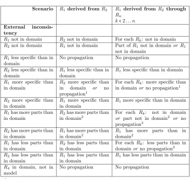
Table 4.2 shows the propagation of external inconsistencies with regard to thederived from relation. A requirement can be derived fromone require-ment, or more. The table makes a distinction between these two cases, as the propagation rules are different.
4.3. External inconsistency propagation 23
Scenario R1 derived from R2 R1 derived from R2 through
Rn
k∈2. . . n
External inconsis-tency
R1not in domain R2 not in domain For each Rk: not in domain
R2not in domain R1 not in domain Part of R1 not in domain or R1
not in domain
R1less specific than in
domain
No propagation No propagation
R2less specific than in
domain
R1 less specific than in
domain
R1 less specific than in domain
R1 more specific than
in domain
R2 more specific than
in domain or no propagation1
For each Rk: more specific than
in domainor no propagation1
R2 more specific than
in domain
R1 more specific than
in domain
R1 more specific than in domain
R1has more parts than
in domain
R2has more parts than
in domain2
For each Rk: not in domain
or part not in domain2 or no propagation3
R2has more parts than
in domain
R1has more parts than
in domain2
R1 has more parts than in
domain2
R1 has less parts than
in domain
R2 has less parts than
in domain
For each Rk: less parts than in
domainor no propagation3
R2 has less parts than
in domain
R1 has less parts than
in domain
R1 has less parts than in domain
R4 in domain, not in
model
No propagation No propagation
1In this scenario, a detail that madeR
1 a derivement from the other requirement(s)
has been removed from the domain. If there are no other such details, the relation or relations are no longer valid and should be removed
2In this scenario, it is possible that the last part whichR
1was deriving from the other
requirement has been removed. If so, the relation is no longer valid and should be removed
3In this scenario, at least one external inconsistency has to be propagated to at least
[image:33.595.99.479.113.470.2]one other requirement
Scenario R1 composed by R2 R1 composed by R2
throughRn
k∈2. . . n
R1 not in domain R2 not in domain For eachRk: not in domain
R2 not in domain R1has more parts than in
do-main
R1has more parts than in
do-main
R1less specific than
in domain
R2 less specific than in
do-mainor no propagation
For each Rk: less specific
than in domain or no prop-agation
R2less specific than
in domain
R1 less specific than in
do-main
R1 less specific than in
do-main
R1 more specific
than in domain
R2 more specific than in
do-mainor no propagation
For each Rk: more specific
than in domain or no prop-agation
R2 more specific
than in domain
R1 more specific than in
do-main
R1 more specific than in
do-main
R1 has more parts
than in domain
R2 not in domain or part
of R2 not in domain or no
propagation1
For each Rk: not in domain
or part not in domain or no propagation1
R2 has more parts
than in domain
R1has more parts than in
do-main
R1has more parts than in
do-main
R1 has less parts
than in domain
No propagation No propagation
R2 has less parts
than in domain
R1 has less parts than in
do-main
R1 has less parts than in
do-main
R4 in domain, not
in model
No propagation No propagation
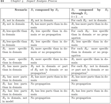
1In this scenario, a part has been removed from R
1 which was not in the other
[image:34.595.149.531.97.455.2]requirement. It is possible that the requirements are now copies and that the relation should be removed.
Table 4.3: External inconsistency propagation rules for the Composed By rela-tion
4.4
Summary
This chapter describes the change impact analysis process and the mappings from domain changes to external inconsistencies to model changes. Lastly, the external inconsistency propagation rules are provided.
5
Formalization of model elements and
changes
This chapter contains the formalization of the relevant SysML model elements and of the domain changes. We also use these formalizations to derive the external inconsistency rules here.
5.1
Introduction
This chapter first describes the relevant SysML model elements. Next, all of these model elements and the domain changes are mathematically formalized. Using these formalizations, the external inconsistency propagation rules are de-rived. Finally, some alternatives for the formalizaton are discussed.
5.2
Relevant SysML model elements
As stated in section 4.3, the relevant model elements areRequirement,Trace, and all subclasses of Trace. The other relations, such as SatisfyandRefine are not considered as of now. Traceand its subclasses are:
Tracerelations define a generic relation between requirements. For read-ability, this relation is calledtraced toin this paper
Compositerelations allow a requirement to contain sub-requirements. For readability, this relation is calledcomposed byin this paper
Copy relations define links between slave and master requirements. For readability, this relation is calledcopy ofin this paper
Derive relations allow one requirement to be derived from another. For readability, this relation is calledderived fromin this paper
5.3
Formalizations
5.3.1
Requirement
A Requirement R consists of a set of predicates P. Each of these predicates evaluate to true or false for any given implementation, or system. They have a textual description and a set of details D applied to them which, in turn, can have details applied to them as well. The details themselves are also textually described, but are meaningless when not associated to a predicate or another detail. Formally, this is denoted as:
R=<P>
P = {p1{<D1>}, p2{<D2>}, . . . , pn{<Dn>}} ∣n≥1
D= {d1{<D1>}, d2{<D2>}, . . . , dm{<Dm>}} ∣m≥0
[image:36.595.244.403.338.381.2]Figure 5.1 shows this formalization in a diagram.
Figure 5.1: Formalization data model
The P in the figure denotes the individual predicates in the requirements, of which a requirement has any number, but at least one. TheD in the figure denotes the individual details in either another detail or a predicate.
Sets of predicates cannot be empty, sets of details can. Details cannot be associated in a cyclical manner. In order to formalize the relation types, we need operators on requirements, predicates and details.
Two predicates are equal to each other with regard to the = operator if and only if their textual descriptions are equal. Details are not considered here
Two details are equal to each other with regard to the = operator if and only if their textual descriptions are equal and they are applied to two predicates which are also equal to each other with regard to the = operator or two details which are also equal to each other with regard to the = operator
Consider a predicate pand a detail d. The detaild is associated to the predicatepif, and only if, it is directly applied to it, or if it is associated to another detail which is associated to the predicate p. ”Detail d is associated to p” is denoted as d∈p.
Consider a predicate pand two detailsd1 andd2, withd1∈pand d2∈p.
The detail d1 is associated to the detail d2 if, and only if, it is directly
5.3. Formalizations 27
When evaluating a predicate pin a system S, p(S)denotes that pwith all detailsd∈pis evaluated to true in systemS.
For the following operator definitions, letR1 andR2 be requirements with
sets of predicatesP1 andP2respectively.
∣P1∣denotes the number of predicates inP1
P1=P2⇔ ∣P1∣ = ∣P2∣ ∧
∀pi∈P1∶ [∃pj∈P2∶ [pi=pj]] ∧
∀pi∈P2∶ [∃pj∈P1∶ [pi=pj]]
P1⊂P2⇔ ∣P1∣ < ∣P2∣ ∧ ∀pi∈P1∶ [∃pj∈P2∶ [pi=pj]]
P1⊆P2⇔P1=P2∨P1⊂P2
R1=R2⇔P1=P2∧
∀pi∈P1∶ [∀pj∈P2∶ [pi=pjÐ→ ∀dk∈pi∶ [dk∈pj]]] ∧
∀pi∈P2∶ [∃pj∈P1∶ [pi=pjÐ→ ∀dk∈pi∶ [dk∈pj]]]
There are a number of rules regarding predicates and details. Consider a systemS. Letp1andp2be predicates with p1=p2.
∀dk∈p1∶ [dk∈p2] ∧p2(S) ⇔p1(S)
∀dk∈p1∶ [dk∈p2] ∧ ¬p1(S) ⇔ ¬p2(S)
A number of assumptions need to be taken into account when regarding this formalization:
Consider a requirementRwith set of predicatesP. Letp1andp2be parts
withp1∈P andp2∈P. Then, for any systemS, the following statement
holds:
p1(S) ⇏ ¬p2(S)
In other words, requirements cannot be internally inconsistent.
Consider a requirementRwith a set of predicatesP, containingp1 topn.
Then, the following statement holds:
∃S∈ U ∶ [pi(S)] ∣i∈1. . . n
In other words, requirements have to be satisfiable.
5.3.2
Formalization of TracedTo
5.3.3
Formalization of DerivedFrom
The derived from relation denotes that one requirement is derived from a number of other requirements. Satisfying the derived requirement implies that the requirements which it was derived from are also satisfied.
LetR1,R2throughRn(withN≥2) be requirements with sets of predicates
P1,P2throughPnrespectively. R1isDerived fromR2throughRnif and only
if the following statements hold:
Pm⊆P1∣m∈2. . . n
∀pi∈P1∶ [∃m∶ [pi∈Pm]] ∣m∈2. . . n
∀pj∈Pm∶ [∀pi∈P1∶ [pi=pjÐ→ ∀dk∈pj∶ [dk∈pi]]] ∣m∈2. . . n
∃pj∈Pm∶ [∃pi∈P1∶ [pi=pj∧ ∃dk∈pi∶ [dk∉pj]]] ∣m∈2. . . n
The first and second statement show thatR1 has all of the predicates of the
other requirements combined, and no more. The third statement shows that all of these predicates have at least all of the details of the parts of the requirements which it is derived from. The fourth statement shows that for every requirement
R1 is derived from, there is at least one detail of a predicate inP1which is not
in a predicate of the other requirement.
5.3.4
Formalization of ComposedBy
Thecomposed by relation denotes that a requirement is contained in another requirement. The containing requirement is, in turn, completely or partially composed of all of its contained requirements.
LetR1,R2 throughRn (withn≥2) be requirements with sets of predicates
P1,P2throughPn respectively. R2throughRnarecomposed byR1if and only
if statement the following statements hold:
Pm⊂P1∣m∈2. . . n
∀pj∈Pm∶ [∀pi∈P1∶ [pi=pjÐ→ ∀dk∈pi∶ [dk∈pj]]] ∣m∈2. . . n
∀pj∈Pm∶ [∀pi∈P1∶ [pi=pjÐ→ ∀dk∈pj∶ [dk∈pi]]] ∣m∈2. . . n
The first statement shows that all predicates in the requirements contained are also in the containing requirement. The second and third statements show that the details in all corresponding predicates are the same.
5.3.5
Formalization of CopyOf
Acopy ofrelation denotes that one requirement is a copy of another.
Let R1 and R2 be requirements with parts P1 and P2 respectively. R1 is
copy ofR2 if and only if the following statements hold:
P1=P2
∀pi∈P1∶ [∀pj∈P2∶ [pi=pjÐ→ ∀dk∈pi∶ [dk∈pj]]]
5.4. Domain change case analysis 29
The first statement shows that the predicates of both requirements are equal. The second and third statements show that the details of all the predicates are also equal. The copy ofrelation is reflexive, symmetric and transitive. This definition is not as strict as in SysML, where there is a difference between slave and master requirements, with slave requirements being unmodifiable. This property is of no concern for this approach, however.
5.4
Domain change case analysis
As specified in section 3.2, the following domain changes are considered in this approach:
New requirement added
Existing requirement removed
Requirement made more specific
Requirement made more abstract
Part removed from requirement
New part added to requirement
These are based on the formalization of the concept of requirement, as pro-vided earlier in this chapter. The domain changes is always first applied to exactly one requirement. Each domain change is a specific change to either the parts of a requirement, or the details. Note that since applying change in this process is partly manual, mistakes can be made. Specifically, a change may be seen as a domain change where actually it is only a model change. The exact difference is this: A change to the model is only a domain change if it alters the sets of systems which satisfy the model. Formally, this can be denoted follows. LetMb be the model before the change, andMa the model after the change.
∃S∈ U ∶ [(Mb(S) ∧ ¬Ma(S)) ∨ (Ma(S) ∧ ¬Mb(S))]
In the following sections,Pb indicates the parts of a requirement before the
change, wherePa denotes those parts afterwards.
5.4.1
New requirement added
A domain change is classified as ”new requirement added” if and only if the following statements hold:
Pb= ∅
Pa≠ ∅
5.4.2
Existing requirement removed
A domain change is classified as ”removing an existing requirement” if and only if the following statements hold:
Pb≠ ∅
5.4.3
Requirement made more specific
A domain change is classified as ”requirement is made more specific” if and only if the following statements hold:
Let detail e{<D>}be added to predicateq.
Pb=Pa
D= ∅
∀pj∈Pb∶ [∀pi∈Pa∶ [pi=pjÐ→ ∀dk∈pj∶ [dk∈pi]]]
∀pj∈Pb∶ [∀pi∈Pa∶ [pi=pjÐ→ ∀dk∈pi∶ [dk∈pj∨dk=e]]]
5.4.4
Requirement made more abstract
A domain change is classified as ”requirement is made more abstract” if and only if the following statements hold:
Let detail ebe removed from predicateq1.
Pb=Pa
∀pj∈Pb∶ [∀pi∈Pa∶ [pi=pjÐ→ ∀dk∈pj∶ [dk∈pi∨dk=e∨dk∈e]]]
∀pj∈Pb∶ [∀pi∈Pa∶ [pi=pjÐ→ ∀dk∈pi∶ [dk∈pj]]]
5.4.5
Part removed from requirement
A domain change is classified as ”part removed from requirement” if and only if the following statements hold:
Let predicateqbe removed.
Pa=Pb−q
∀pj∈Pb∶ [∀pi∈Pa∶ [pi=pjÐ→ ∀dk∈pj∶ [dk∈pi]]]
∀pj∈Pb∶ [∀pi∈Pa∶ [pi=pjÐ→ ∀dk∈pi∶ [dk∈pj]]]
5.4.6
New part added to requirement
A domain change is classified as ”new part added to requirement” if and only if the following statements hold:
Let predicateq{<D>}be added.
Pa=Pb+q
D= ∅
∀pj∈Pb∶ [∀pi∈Pa∶ [pi=pjÐ→ ∀dk∈pj∶ [dk∈pi]]]
5.5. Propagation rule derivation 31
5.5
Propagation rule derivation
The derivation of the external inconsistency propagation rules as shown in chap-ter 4 is based on the formalization of requirement, the relation types and the domain changes. Every combination of relation type and domain change re-quires an external inconsistency propagation rule. This derivation is performed with these rationale.
1 The rules guarantee that the (remaining) relations in the resulting require-ments model are all still valid
2 When a domain change specifies that a part or detail is removed from a requirement, it should be removed from the entire requirement model
This derivation is shown here, grouped first by domain change.
5.5.1
New part added to requirement
A domain change is classified as ”new part added to requirement” if and only if the following statements hold:
Consider predicateq1 to be added.
Pa=Pb+q1
∀pj∈Pb∶ [∀pi∈Pa∶ [pi=pjÐ→ ∀dk∈pj∶ [dk∈pi]]]
∀pj∈Pb∶ [∀pi∈Pa∶ [pi=pjÐ→ ∀dk∈pi∶ [dk∈pj]]]
Consider the composition relation. It is formalized as:
Let R1, R2 through Rn (with n ≥ 2) be requirements with parts P1, P2
through Pn respectively. R2 through Rn are composed by R1 if and only if
statement the following statements hold:
Pm⊂P1∣m∈2. . . n
∀pj∈Pm∶ [∀pi∈P1∶ [pi=pjÐ→ ∀dk∈pi∶ [dk∈pj]]] ∣m∈2. . . n
∀pj∈Pm∶ [∀pi∈P1∶ [pi=pjÐ→ ∀dk∈pj∶ [dk ∈pi]]] ∣m∈2. . . n
First, consider the domain change being applied toR2. This implicates that
P2 corresponds toPb before the change and toPa after the change.
There are two possible scenarios. For each scenario, the two rationale are considered to determine necessary action:
Scenario 1: q1∈P1
This implies:
P2⊆P1
In this scenario, the change made is not a domain change as it does not alter the set of systems which satisfy the model.
Scenario 2: q1∉P1
P2⊄P1∧P2≠P1
In this scenario, the relation no longer holds. Here, we propagate the domain change toR1.
Consider predicate q2 to be added.
Pa=Pb+q2
∀pj∈Pb∶ [∀pi∈Pa∶ [pi=pjÐ→ ∀dk∈pj∶ [dk∈pi]]]
∀pj∈Pb∶ [∀pi∈Pa∶ [pi=pjÐ→ ∀dk∈pi∶ [dk∈pj]]]
Then, for R1 we have P1b, the predicates before the new change has been
applied, andP1a, the predicates after the new change has been applied.
Then we have,P1a=P1b+q2. If the change is correctly implemented,q1=q2.
I.e. the addition to the R1 is the same as the addition toR2. If so, the
state-ments which have to hold for the composition relation between R1 and R2 to
be valid, hold.
From this analysis, we can determine that there are two possible propagation scenarios:
No propagation
Apply domain change ”New part added to requirement” toR2
Next, consider the domain change being applied toR1. This implicates that
P1 corresponds toPb before the change and to Pa after the change. Here, the
statements which much hold for the composition relation between R1 and R2
throughRn to be valid, hold.
From this analysis, we can determine that there is only one possible propa-gation scenario:
No propagation
5.5.2
Requirement made more abstract
A domain change is classified as ”requirement made more abstract” if and only if the following statements hold:
Let detail ebe removed from predicateq1.
Pb=Pa
∀pj∈Pb∶ [∀pi∈Pa∶ [pi=pjÐ→ ∀dk∈pj∶ [dk∈pi∨dk=e∨dk∈e]]]
∀pj∈Pb∶ [∀pi∈Pa∶ [pi=pjÐ→ ∀dk∈pi∶ [dk∈pj]]]
Consider the derivement relation. It is formalized as:
LetR1,R2 throughRn (withn≥2) be requirements with sets of predicates
P1,P2throughPnrespectively. R1isDerived fromR2throughRnif and only
if the following statements hold:
5.6. Discussion of formalization 33
∀pi∈P1∶ [∃m∶ [pi∈Pm]] ∣m∈2. . . n
∀pj∈Pm∶ [∀pi∈P1∶ [pi=pjÐ→ ∀dk∈pj∶ [dk ∈pi]]] ∣m∈2. . . n
∃pj∈Pm∶ [∃pi∈P1∶ [pi=pj∧ ∃dk∈pi∶ [dk∉pj]]] ∣m∈2. . . n
First, consider the domain change being applied toR1. This implicates that
P1 corresponds toPb before the change and toPa after the change. Then, for
each requirement R2 through Rn, the possible scenarios are the same, so we
only considerR2 here.
Scenario 1: q1∉P2
In this scenario, the statements which have to hold for the relation betweenR1
andR2 to be valid, hold.
Scenario 2: q1∈P2∧p∈P2∶ [p=q1∧e∈p]
In this scenario, the statements which have to hold for the relation between
R1 and R2 to be valid, hold. However, considering the first propagation rule
derivation rationale, since the detail is removed fromR1 and is present inR2,
it should also be removed there.
Scenario 3: q1∈P2∧p∈P2∶ [p=q1∧e∉p]
In this scenario, the fourth statement which have to hold for the relation between
R1andR2 to be valid, may or may not still hold. This can be evaluated by the
following statement:
∃pj∈P2∶ [∃pi∈P1∶ [pi=pj∧ ∃dk∈pi∶ [dk∉pj∧dk≠e]]]
In natural language, R1 needs to have another detail apart from e which
makes it a derivation ofR2. If the previous statement evaluates to false, it does
not and the relation is no longer valid. Otherwise, there are no inconsistencies. In both cases however, there is no external inconsistency propagation. From this analysis, we can determine that there are two possible propagation scenarios:
Apply domain change ”requirement made more abstract” toR2
No propagation
Note that in case the change is not propagated, the validity of the relation needs to be checked.
5.6
Discussion of formalization
5.6.1
Using predicates and systems
[GKvdB09] formalizes requirements using predicates, similar to us, and systems. This is most likely is sufficient. Formalizing the relations is possible and ade-quate, as well as deriving the external inconsistency propagations rules. In fact, the difference between using predicates and systems and the current approach lies only in the explicit nature of the details. However, we believe that using parts and details as opposed to predicates and systems makes the derivation of the external inconsistency propagation rules more clear. As stated before, domain changes include removing and adding parts and details. Directly incor-porating these in the formalization of the requirements and the relations creates a much clearer link between these formalizations and the derivation of the rules. Another thing to note is that there is some redundancy when using predicates and systems, as the systems which satisfy a requirement can be derived from its predicates.
5.6.2
Using systems only
We also attempted to create a formalization of each of the relevant model ele-ments using only systems. This created a problem concerning thederived from and thecomposed byrelation types. Without further information, thederived from relation type only states the necessity of a subset relation between the systems of two requirements. This would however, by definition create aderived from relation to a composed requirement from each of its components.
Since the SysML specifications are not entirely clear on the definitions of these relation types, this could be interpreted as perfectly fine formalizations. However, we felt it would increase the value of the entire metamodel if the derived from were not just a reversedcomposed by relation. This is why we needed additional information.
5.7
Summary
This chapter first formalized requirements as a collection of parts which can have details applied to them. Using this formalization, the various relation types were formalized; DerivedFrom, ComposedBy and CopyOf. The domain changes were formalized as the difference between the parts and details of a single requirement before and after the domain change has been determined.
Next, rules with which the external inconsistencies are propagated were de-termined. Only a small number of scenarios were described. These scenarios consist of one domain change, two requirements and one relation between the two requirements. The rule determination was done by combining the formaliza-tions of requirement, relaformaliza-tions and domain changes. We also shortly discussed alternative requirement formalizations.
6
Example process usage
In this chapter we show how the process described in the previous chapters can be used in practice.
6.1
Example Model
As an example model we use a subset of a fictional Course Management System for a fictional university [CMS]. There are four stakeholders in this system:
Students
Lecturers (in the example model shown here labeled as teachers)
Administrators
System maintainers
The main subject of the system are the courses. Course information such as roster, lecturer, enrolled students and news messages can be managed, as well as personal information regarding students and lecturers. Note that the example intentionally contains some conflicting requirements, mostly between different stakeholders. For each stakeholder, there are also a number of non-functional requirements, such as privacy, security and interoperability.
We show the working of our process using a subsection of the requirements which regards the functionality for the lecturers to manage dynamic course information. This involves the following:
Posting news messages for a course. Only students enrolled in that course can read them.
Managing the course archive. The archive contains items such as home-work assignments and lecture sheets.
Managing student teams. Lecturers can create student teams for a course and manage them.
Managing student grades for a course.
Importing course information from one year into another, so that the lecturer doesn’t have to re-enter a lot of the information again every year.
We chose this subset because it is relatively easy to understand and because it contains bothDerivedFromandComposedByrelations. The example does not contain the CopyOfrelation, no conflicting requirements and no non-functional requirements.
[image:46.595.151.504.313.549.2]Figure 6.1 shows the requirements model of the subsection of the Course Managament System in a graphical notation. The specifics can be found in appendix B.
Figure 6.1: Example Requirements model
The dots in the figure between T11.3.2 and T11.3.7 mark the requirements T11.3.3 to T11.3.6. The dotted lines in the figure indicate that there is some relation between the predicates of the requirements connected with this line, but this relation is not of a type specified in SysML.
6.2
Example changes
6.2. Example changes 37
Teachers will no longer be allowed to set the visibility of items in the archive
Student teams need no longer be supported by the system
Teachers have to be able to remove grades as well as storing them
6.2.1
Remove setting visibility of archived items
As specified by the process, the domain change first has to be decomposed into an atomic domain change, but how this is done is not elaborated upon. This specific domain change however, can only be decomposed and applied correctly in one way: By applying the domain change ”Requirement made more abstract” to requirement T11.2.1.
The domain change is then mapped automatically to the external inconsis-tency ”Requirement in the model more specific than in the domain”, as stated in table 4.1, and applied to T11.2.1. The process then picks requirement T11.2 to be handled next, as it is the only related requirement. The scenario in this case is: T11.2.1 is designated externally inconsistent as ”Requirement in the model more specific than in the domain” and is related to T11.2 by theDerivedFrom relation, with T11.2.1 as the source. As specified in table 4.2, there are two propagation possibilities:
To apply the external inconsistency ”Requirement in the model more spe-cific than in the domain” to T11.2
Not to propagate an external inconsistency
This choice is made by the requirements engineer, who we assume makes the second choice, being the correct one for this domain change. Note that table 4.2 contains a foot-note on this scenario, namely that the two requirements may have become identical. It is up to the requirements engineer to solve this issue. Since no other requirements are related to T11.2.1 and T11.2 is designated not externally inconsistent, the propagation ends. The process then maps the inconsistency to a proposed model change, according to table 4.1. The result is shown in table 6.2.1.
Requirement External Inconsistency Proposed
model change
T11.2.1 Requirement in the model more specific than in the domain
Detail removed from requirement
Table 6.1: Process result for example one
6.2.2
Remove student team support
Again, the requirements engineer has to decompose and apply the domain change. In this case, the fact that the system needs no longer support stu-dent teams implies that teachers need no longer be able to manage them. This domain change can be handled in several ways:
Applied to requirement T11.3 as ”Existing requirement removed”
Applied to requirement T11 as ”Part removed from requirement”
Applied to requirements T11.3.2 to T11.3.7 as ”Existing requirement re-moved”
It is up to the requirements engineer to choose which is most practical, but note that requirement T11.3.1 needs also be designated as ”Existing requirement removed”, as it is not related to any other requirement in the model by a SysML specified relation. Whichever approach the engineer chooses, the results are the same, provided the correct propagation possibilities are selected. For this example, we assume the domain change ”Existing requirement removed” is applied to T11.3. The other options are not elaborated upon here.
The domain change is automatically mapped to the external inconsistency ”Requirement not in the domain, but present in the model”, as stated in table 4.1, and applied to T11.3. The process then randomly picks a requirement related T11.3 to handle next, but whichever order the requirements are handled in, the results are the same given that the requirements engineer selects the correct propagation possibilities. We assume T11.3.2 is picked first.
The scenario being handled in this particular situation is: T11.3 is designated externally inconsistent as ”Requirement not in the domain, but present in the model” and is related to T11.3.2 by theComposedByrelation, with T11.3 as the source. As specified in table 4.3, there is only one propagation possibility: To apply the same external inconsistency to T11.3.2.
After this step, the process selects another random requirement related to either T11.3 or T11.3.2. As T11.3.2 is not related to any requirement which has not been processed yet, a requirement related to T11.3 will be selected. We assume the process first selects the requirements T11.3.3 to T11.3.7. These requirements are handled in exactly the same manner as T11.3.2.
Finally, the process will select T11. The scenario in this case is: T11.3 is designed externally inconsistent as ”Requirement not in the domain, but present in the model” and is related to T11 by the ComposedBy relation, with T11 as the source. As specified in table 4.3, there is only one propagation possibility: To apply the external inconsistency ”Requirement in the model has more parts than in the domain” to T11.
As a last step, the process selects T11.2. The scenario in this case is: T11 is designated externally inconsistent as ”Requirement in the model has more parts than in the domain” and is related to T11.2 by theComposedBy relation, with T11 as the source. As specified in table 4.3, there are three propagation possibilities:
6.2. Example changes 39
To apply the external inconsistency ”Requirement in the model has more parts than in the domain” to T11.2
Not to propagate an external inconsistency
This choice is made by the requirements engineer, who we assume makes the third choice, being the right one for this domain change. At this point, as there are no requirements related to requirements with an external inconsistency applied to them which have not yet been handled, the propagation ends.
The next step is for the process to automatically map the external incon-sistencies to proposed model changes. This mapping is done according to table 4.1 and the results are shown in the table 6.2.2.
Requirement External Inconsistency Proposed model change
T11 Requi
![Figure 2.1: OMG architectural layers. Based on [OMG02]](https://thumb-us.123doks.com/thumbv2/123dok_us/1207446.644313/18.595.237.411.126.394/figure-omg-architectural-layers-based-on-omg.webp)

![Figure 2.3: UML and SysML. [OMG07a]](https://thumb-us.123doks.com/thumbv2/123dok_us/1207446.644313/20.595.215.433.526.686/figure-uml-and-sysml-omg-a.webp)
![Figure 2.4: Diagrams in SysML. [OMG07a]](https://thumb-us.123doks.com/thumbv2/123dok_us/1207446.644313/21.595.120.426.273.403/figure-diagrams-in-sysml-omg-a.webp)
![Figure 2.5: Change management process. [KS98]](https://thumb-us.123doks.com/thumbv2/123dok_us/1207446.644313/23.595.126.424.501.613/figure-change-management-process-ks.webp)