Abstract—We focus in this paper on the specification and the
execution of behavioral concepts for Open Distributed Processing (ODP) Enterprise Language. The behavior of an ODP system is determined by the collection of all the possible actions in which the system (acting as an object), or any of its constituent objects, might take part, together with a set of constraints on when these actions can occur. In order to specify the executable behavior of a system and to make the processes of the enterprise executable and controllable, the Reference Model for ODP RM-ODP can be used as a meta-model for behavioral specifications. In the enterprise language the behavior is specified in terms of roles, processes, policies, and the relationships between these concepts. Firstly, we give the description and specification of the behavior by the activity diagrams. Secondly, we define the mapping from the concepts of behavior enterprise language to BPEL concepts and we present the syntax and the structure of a BPEL Behavior process. Then we generate the corresponding BPEL and computational files to implement the specified process.
Index Terms—RM-ODP, Enterprise Language, Behavior
Business Process Model, BPEL
I. INTRODUCTION
The rapid growth of distributed processing has led to a need for coordinating framework for the standardization of Open Distributed Processing (ODP). The Reference Model for Open Distributed Processing (RM-ODP) [1-4] provides a framework within which support of distribution, networking and portability can be integrated. The foundations part [2] contains the definition of the concepts and analytical framework for normalized description of (arbitrary) distributed processing systems. These concepts are grouped in several categories. The architecture part [3] contains the specifications of the required characteristics that qualify distributed processing as open. It defines a framework comprising five viewpoints, viewpoint language, ODP functions and ODP transparencies. The five viewpoints, called enterprise, information, computational, engineering and technology provide a basis for the specification of ODP systems.
Each viewpoint language defines concepts and rules for specifying ODP systems from the corresponding viewpoint. The ODP functions are required to support ODP systems.
Youssef Balouki, Department of Mathematics & Computer Science, University Mohammed V Morocco, email: [email protected]
Mohamed Bouhdadi, Department of Mathematics & Computer Science, University Mohammed V Rabat, Morocco, email: bouhdadi@ fsr.ac.ma). The transparency prescriptions show how to use the ODP
functions to achieve distribution transparency. The first three viewpoints do not take into account the distribution and heterogeneity inherent problems. This corresponds closely to the concepts of PIM (Plat-form Independent Model) and PSM (Plat-form Independent Model) models in the OMG MDA architecture.
However, RM-ODP can not be directly applicable [5]. In fact RM-ODP only provides a framework for the definition of new ODP standards. These standards include standards for ODP functions [6-7]; standards for modelling and specifying ODP systems; standards for programming, implementing, and testing ODP systems.
We treated the need of formal notation for behavioural concepts in the enterprise language [8]. Indeed, the viewpoint languages are abstract in the sense that they define what concepts should be supported, not how these concepts should be represented. It is important to note that, RM-ODP uses the term language in its broadest sense:" a set of terms and rules for the construction of statements from the terms;” it does not propose any notation for supporting the viewpoint languages. Using the Unified Modelling Language (UML)/OCL (Object Constraints Language) [9, 10] we defined a formal semantics for a fragment of ODP behaviour concepts defined in the RM-ODP foundations part and in the enterprise language [11]. These concepts (time, action, behaviour constraints and policies) are suitable for describing and constraining the behaviour of ODP enterprise viewpoint specifications.
A part of UML meta-model itself has a precise semantics [12, 13] defined using denotational meta-modelling approach. A denotational approach [14] is realized by a definition of the form of an instance of every language element and a set of rules which determine which instances are and are not denoted by a particular language element.
For testing ODP systems [2-3], the current testing techniques [15], [16] are not widely accepted. A new approach for testing, namely agile programming [17], [17] or test first approach [19] is being increasingly adopted. The principle is the integration of the system model and the testing model using UML meta-modelling approach [20, 21]. This approach is based on the executable UML [22].
In this context OCL is used to specify the properties to be tested. The UML meta-models provide a precise core of any ODP testers.
In this context we use in this paper the BPEL (Business Process Execution Language for Web Services) (BPEL4WS or BPEL for short) for specifying process behaviour based on actions and policies in the context of ODP systems. The Business Process Execution Language for Web Services (BPEL4WS or BPEL for short) is an XML-based standard
A UML Profile for Automated Behavior
Processes in ODP Enterprise Language
for de fining how you can combine Web services to implement business processes. It builds upon the Web Services Definition Language (WSDL) and XML Schema Definition (XSD). This article specifies the behavior processes by the activity diagrams, and generates the corresponding BPEL and computational files to implement that process. This capability is used to highlight some of the benefits of the Object Management Groups (OMG) Model Driven Architecture (MDA) initiative: raising the level of abstraction at which development occurs, which, in turn, will deliver greater productivity, better quality, and insulation from underlying changes in technology.
The paper is organized as follows. Section 2 introduces, both BPEL and the core behaviour concepts (time, action, behaviour, role, process). Section 3 describes and specifies the behaviour by the activity diagrams. In Section 4 we define the mapping from the concepts of behavior enterprise language to BPEL concepts and we present the syntax and the structure of a BPEL Behaviour process. We focus on behavioural policies. A conclusion ends the paper.
II. PRELIMINARIES A. BPEL
BPEL, also known as BPEL4WS, build on IBM's WSFL (Web Services Flow Language) and Microsoft's XLANG (Web Services for Business Process Design). It combines the features of a block structured process language (XLANG) with those of a graph-based process language (WSFL). BPEL is intended to describe a business process in two different ways: executable and abstract processes. An abstract process is a business protocol specifying the message exchange behavior between different parties without revealing the internal behaviour of any of them. An executable process specifies the execution order between a number of constituent activities, the partners involved, the message exchanged between these partners, and the fault and exception handling mechanisms.
A composite service in BPEL is described in terms of a process. Each element in the process is called an activity. BPEL provides two kinds of activities: primitive activities and structured activities. Primitive activities perform simple operations such as receive (waiting for a message from an external partner), reply (reply a message to a partner), invoke (invoke a partner), assign (copying a value from one place to another), throw (generating a fault), terminate (stopping the entire process instance), wait (wait for a certain time), empty (do nothing),.
To en able the representation of complex structures, a structured activity is used to define the order on the primitive activities. It can be nested with other structured activities. The set of structured activities includes: sequence (collection of activities to be performed sequentially), flow (specifying one or more activities to be performed concurrently), while (while loop), switch (selects one control path from a set of choices), pick (blocking and waiting for a suitable message). The most important structured activity is a scope. A scope is a means of explicitly packaging activities together such that they can share common fault handling and compensation routines. It consists of a set of option al fault handlers (exceptions can
be handled during the execution of its enclosing scope), a single optional compensation handler (inverse some effects which happened during the execution of activities), and the primary activity of the scope which defines its behavior .
[image:2.612.314.541.344.528.2]The sequence, flow, switch, pick and whi1e constructs provide a means of expressing structured flow dependencies. In addition to these constructs, BPEL provides another construct known as control links which, together with the associated notions of join condition and transition condition, support the definition of precedence, synchronization and conditional dependencies on top of those captured by the structured activity constructs. A control link between activities A and B indicates that B cannot start before A has either completed or has been skipped. Moreover, B can only be executed if its associated join condition evaluates to true, otherwise B is skipped. An activity X propagates a positive value along an outgoing link L if and only if X was executed (as opposed to being skipped) and the transition condition associated to L evaluates to true. Transition conditions are Boolean expressions over the process variables. The process by which positive and negative values are propagated along control links, causing activities to be executed or skipped, is called dead path elimination.
Figure 1 defines the BPEL core concepts [23]
Fig. 1 Model of BPEL Core Concepts
B. The Core behavioral Concepts in RM-ODP Foundations Part
roles of the community, together with a set of constraints on when these actions may occur, It may be of interest to specify which actor (enterprise object) initiates that action.
There are many specification styles for expressing when actions may occur (e.g. sequencing, pre-conditions, partial ordering, etc.).The actions and their ordering can be defined in terms of processes.
A process identifies an abstraction of the community behaviour that includes only those actions that are related to achieving some particular sub-objective within the community. Each abstraction is labelled with a process name. The emphasis is on what the behaviour achieves. Processes decompose the behaviour of the community into steps. Its specification shall include specification of how it is initiated and how it terminates.
We represent a concurrent system as a triple consisting of a set of behavior, a set of process and a set of action. Each behavior is modeled as a finite or infinite sequence of interchangeable behavior and actions. To describe this sequence there are mainly two approaches [24].
1. “Modeling systems by describing their set of actions and their behaviors”.
2. “Modeling systems by describing their action spaces and their possible sequences of action changes”.
[image:3.612.313.543.147.285.2]These views are dual in the sense that an behavior can be understood to define action changes, and action occurring in action sequences can be understood as abstract representations of process. We consider both of these approaches as abstraction of the more general approach based on RMODP. We provide the formal definition of this approach that expresses the business process models.
Fig. 2 Core Behavior Concepts
III. UML PROFILE FOR AUTOMATED BEHAVIOR PROCESSES The ability to extend or customize UML is essential to MDA; UML can be customized to support the modelling of the systems behavior. The scope of this article is mainly centred on stereotypes. Stereotypes are a way of categorizing elements of a model. We can combine a set of these stereotypes in a Profile. A UML Profile is used to define a specific set of extensions to the base UML in order to represent a particular domain of interest. For instance
there are Profiles defined for CORBA and Data Modelling. A profile defines what elements of UML are to be used, how they may be extended, and any well-formedness rules to constrain the assembly of the elements.
[image:3.612.71.298.416.619.2]This section introduces a UML Profile which supports modelling with a set of semantic constructs that correspond to those in the Business Process Execution Language for behavior in enterprise language (see table 1).
Table 1 Behavior concepts to UML mapping overview
We represent a subset of the UML profile through an example that defines a simple behavior process. It may be summarized as follows:
"On receiving the action request, the condition of action is checked. If it is true, then the actor3 action is invoked. If the Actor2 deems the action constraint is not checked , it is also passed to the Actor3. When either the Actor3 has completed or the Actor2 has accepted, the objective information is returned.''
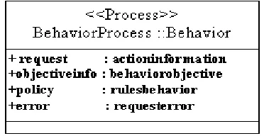
BPEL processes are stateful and have instances, so in BPEL this scenario is implemented as a behavior process which would have an instance for each actual behavior application being processed. Each instance has its own state which is captured in BPEL variables. In the UML profile, a process is represented as a class with the stereotype <<Process>>. The attributes of the class correspond to the state of the process (variables in BPEL 1.1). The UML class representing the behaviourl process is shown in Figure 3.
Fig. 3 A UML class used to model a Behavior BPEL Process
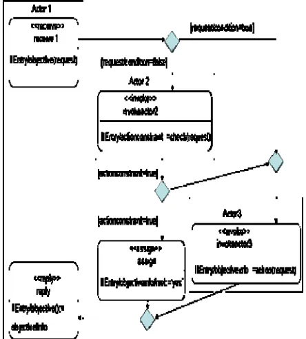
The behavior of the class is described using an activity graph. The activity graph for the behavior process is shown in figure 4. The activities, such as invokeAactor2, are shown as the rectangles with rounded corners. The actions to be performed are shown as Entry conditions to the activity. For example, action constraint (a variable) is set to
Behavior Concepts Profile Construct Process_El << process>> class
Action Activity graph on a
<<process>> class
Actor <<partner>> class
Policy <<process>> class attributes
Objective Hierarchical structure and
control flow <<receive>>,
<<reply>>,
<<invoke>> actions
[image:3.612.319.505.535.631.2]the result of the check service. The actors with which the process communicates are represented by the UML partitions (also known as swimlanes): Actor1, Actor2, and Actor3. Activities that involve a message send or receive operation to an actor appear in the corresponding partition. The arrows indicate the order in which the process performs the activities. Note that the assignment activity is not in a swimlane; it depicts an action that takes place within the process itself.
Fig. 4 An Activity Diagram for the Behavior Process
The reply activity returns a response back to the actor1, completing the execution of the process. Each activity has a descriptive name and an entry action detailing the work performed by the activity.
IV. MAPPING TO BPEL A. From UML to BPEL
The UML profile for automated behavior processes expresses that complete executable BPEL artifacts can be generated from UML models. Table 2 shows an overview of the mapping from the profile to BPEL covering the subset of the profile introduced in this article.
B. Execution of the Behavior processes
BPEL is representation XML of an executable process, which can be deployed on any process motor.
Table 2. UML to BPEL mapping overview
The atomic element of a process BPEL is a " activity ", which can be the sending of a message, the reception of a message, the call of an operation (sending of a message, makes an attempt of an answer), or a transformation of data
A process BPEL defines, in XML, the activities realized within the framework of the execution of the behavior process .In the following we describe his structure and his syntax .
< el_behavior >
< actors /> Æ definition of the actors (roles) <containers/> Æ definition of the containers of the data <transitioncondition>
<policies /> Æ A set of rules related to a behavior. </transitioncondition>
<sequence/>
<receive /> Æ reception of a request of process <assign /> Æ transformation of the data <invoke /> Æ call of an process
<assign /> Æ transformation of the data <reply /> Æ sending of an answer to the process </sequence>
</el_behavior > <process >
< partners /> Æ definition of the partners (actions) <containers/> Æ definition of the containers of the data <sequence />
<receive /> Æ reception of a request <assign /> Æ transformation of the data <invoke /> Æ call of an action
<assign /> Æ transformation of the data <reply /> Æ sending of an answer </sequence>
</process>
<policies> name = "namepolicy" <process name ="process"/> < actors name = "actor"/> <choice >
<policy type ="obligations"/> <policy type ="permissions"/> <policy type ="prohibitions"/> <policy type ="authorizations"/> </choice >
</policies>
A cutdown version of the BPEL document that would be generated from the behavior process example in this paper
Profile Construct BPEL Concept
<< process>> class BPEL process definition Activity graph on a
<<process>> class
BPEL activity hierarchy <<process>> class attributes BPEL variables Hierarchical structure and
control flow
BPEL sequence and flow activities
<<receive>>, <<reply>>, <<invoke>>activities
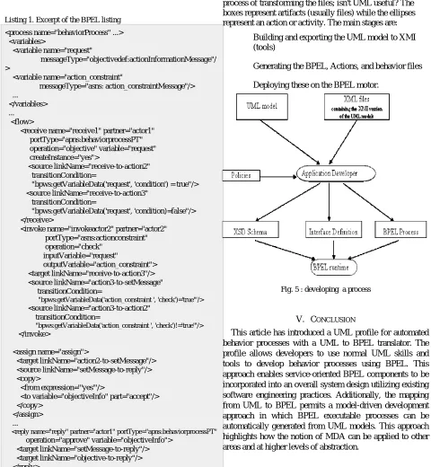
is shown in Listing 1 (much of the detail is omitted here due to space constraints).
Listing 1. Excerpt of the BPEL listing
<process name="behaviorProcess" ...> <variables>
<variable name="request"
messageType="objectivedef:actionInformationMessage"/ >
<variable name="action_constraint"
messageType="asns: action_constraintMessage"/> ...
</variables> ...
<flow>
<receive name="receive1" partner="actor1" portType="apns:behaviorprocessPT" operation="objective" variable="request" createInstance="yes">
<source linkName="receive-to-action2" transitionCondition=
"bpws:getVariableData('request', 'condition') = true"/> <source linkName="receive-to-action3"
transitionCondition=
"bpws:getVariableData('request', 'condition)=false"/> </receive>
<invoke name="invokeactor2" partner="actor2" portType="asns:actionconstraint" operation="check"
inputVariable="request"
outputVariable="action_constraint"> <target linkName="receive-to-action3"/> <source linkName="action3-to-setMessage" transitionCondition=
"bpws:getVariableData('action_constraint ', 'check')='true'"/> <source linkName="action3-to-action2"
transitionCondition=
"bpws:getVariableData('action_constraint ', 'check')!='true'"/> </invoke>
<assign name="assign">
<target linkName="action2-to-setMessage"/> <source linkName="setMessage-to-reply"/> <copy>
<from expression="'yes'"/>
<to variable="objectiveInfo" part="accept"/> </copy>
</assign> ...
<reply name="reply" partner="actor1" portType="apns:behaviorprocessPT" operation="approve" variable="objectiveInfo">
<target linkName="setMessage-to-reply"/> <target linkName="objective-to-reply"/> </reply>
</flow> </process>
C. The UML to BPEL Mapping Transformation t
The approach comes with a set of sample files for different scenarios [25]. The sample files are of two main types: UML model files which can be opened and modified with tools, and XML files containing the XMI version of the UML models, which are exported by theme. In figure 5 you
can see that this corresponds to the UML models, or the XMI output of these tools.
Figure 5 uses a UML Activity Diagram to show the overall process of transforming the files; isn't UML useful? The boxes represent artifacts (usually files) while the ellipses represent an action or activity. The main stages are:
• Building and exporting the UML model to XMI (tools)
[image:5.612.65.545.83.603.2]• Generating the BPEL, Actions, and behavior files • Deploying these on the BPEL motor.
Fig. 5 : developing a process
V. CONCLUSION
This article has introduced a UML profile for automated behavior processes with a UML to BPEL translator. The profile allows developers to use normal UML skills and tools to develop behavior processes using BPEL. This approach enables service-oriented BPEL components to be incorporated into an overall system design utilizing existing software engineering practices. Additionally, the mapping from UML to BPEL permits a model-driven development approach in which BPEL executable processes can be automatically generated from UML models. This approach highlights how the notion of MDA can be applied to other areas and at higher levels of abstraction.
REFERENCES
[1] ISO/IEC, ‘’Basic Reference Model of Open Distributed Processing-Part1: Overview and Guide to Use, ‘’ISO/IEC CD 10746-1, 1994 [2] ISO/IEC, ‘’RM-ODP-Part2: Descriptive Model, ‘’ ISO/IEC DIS
10746-2, 1994.
[3] ISO/IEC, ‘’RM-ODP-Part3: Prescriptive Model, ‘’ ISO/IEC DIS 10746-3, 1994.
[4] ISO/IEC, ‘’RM-ODP-Part4: Architectural Semantics, ‘’ ISO/IEC DIS 10746-4, July 1994.
[6] ISO/IEC, ‘’ODP Type Repository Function, ‘’ ISO/IEC JTC1/SC7 N2057, 1999.
[7] ISO/IEC, The ODP Trading Function, ISO/IEC JTC1/SC21 1995. [8] ISO/IEC, ‘’RM-ODP Enterprise Langauge,’’ ISO/IEC 15414, July 2006. [9] . J. Rumbaugh, G. Booch, J. E. Jacobson, The Unified Modeling
Language, Addison Wesley, 1999.
[10] J. Warner and A. Kleppe, The Object Constraint Language: Precise Modeling with UML, Addison Wesley, 1998.
[11] M. Bouhdadi, Y. Balouki, ‘’Meta-modelling Semantics of Behavioral Concepts for Open Virtual Enterprises,’’ ECC 2007, Athens 25-27 Sep, Springer Verlag (to appear
[12] S. Kent, S. Gaito, N. Ross, ‘’A meta-model semantics for structural constraints in UML, ‘, In H. Kilov, B. Rumpe, and I. Simmonds, editors, Behavioral specifications for businesses and systems, Kluwer Academic Publishers, Norwell, MA, September 1999. chapter 9. [13] E. Evans, R. France, K. lano, B. Rumpe, ‘’Meta-Modeling Semantics
of UML, ‘’ In H. Kilov, B. Rumpe, and I. Simmonds, editors, Behavioral specifications for businesses and systems, Kluwer Academic Publishers, Norwell, MA, September 1999. chapter 4 [14] D.A. Schmidt, ‘’Denotational semantics: A Methodology for
Language Development, ‘’ Allyn and Bacon, Massachusetts, 1986. [15] G. Myers, ‘’The art of Software Testing, ‘’, John Wiley &Sons, 1979 [16] R. Binder, ‘’ Testing Object Oriented Systems. Models. Patterns, and
Tools, ‘’ Addison-Wesley, 1999
[17] A. Cockburn, ‘’Agile Software Development. ‘’Addison-Wesley, 2002.
[18] B. Rumpe, ‘’ Agile Modeling with UML, ‘’ LNCS vol. 2941, Springer, 2004, pp. 297-309.
[19] K. Beck. Column on Test-First Approach. IEEE Software, vol. 18, no. 5, pp.87-89, 2001
[20] L. Briand , ‘’A UML-based Approach to System testing, ‘’ LNCS vol. 2185. Springer, 2001, pp. 194-208,
[21] B. Rumpe, ‘’ Model-Based Testing of Object-Oriented Systems; ‘’ LNCS vol.. 2852, Springer; 2003; pp. 380-402.
[22] B. Rumpe, Executable Modeling UML. A Vision or a Nightmare?, In: Issues and Trends of Information technology management in Contemporary Associations, Seattle, Idea Group, London, pp. 697-701.
[23] Dimitris Karagiannis et al. Business-oriented IT management developing e-business applications with E-BPMS,’’ ICEC 2007, 97-100
[24] M. Broy, ‘’Formal treatment of concurrency and time,’’ Software Engineers’s Reference Book, Oxford Butterworth-Henenmann (1991). [25] keith_mantell,” From UML to BPEL Model Driven Architecture in a
![Figure 1 defines the BPEL core concepts [23]](https://thumb-us.123doks.com/thumbv2/123dok_us/1328990.663796/2.612.314.541.344.528/figure-defines-the-bpel-core-concepts.webp)