EPC To BPEL Transformations
Lucas O. Meertens [email protected]
Version: final (v Edited: 1/22/2009
EPC To BPEL Transformations
Lucas O. Meertens [email protected]
EPC To BPEL Transformations
January 2009
Graduation thesis of: Lucas O. Meertens
Student number 0037141
Business Information Technology University of Twente
On behalf of:
Sogeti Nederland B.V. Lange Dreef 17 4131 NJ Vianen
Under supervision of:
Dr. M.E. Iacob (University of Twente, faculty of MB)
Abstract
Companies looking to improve their business processes can choose from several approaches. Almost all of these include modeling the processes. Implementing the modeled processes is the next step. Usually, developers create the required software, based on the models. However, often the resulting code does not meet the demands of the business. In order to improve the transition from business process models to code, Model-Driven Engineering (MDE) provides a promise by using model transformation. This promise consists of the ability to change business models into code automatically.
This research investigates one of the possible model transformations. Namely, the transformation from Event-driven Process Chains (EPC) models to Business Process Execution Language (BPEL) specifications. Business modelers use EPC to create process models of the control flow. IT developers can use the resulting BPEL specifications as executable code, which contains the control flow.
A conceptual model provides a method for evaluating model transformation. Ontology (the BWW model) and workflow patterns form its basis. According to the conceptual model, it is possible to transform most patterns and constructs from EPC to BPEL. However, one pattern is impossible to transform, and several constructs cause ambiguities. A conceptual mapping from EPC to BPEL offers one way to deal with these issues.
structuring is impossible, decomposing the model into smaller diagrams is a solution. This can lead to irrational diagrams from a modeler’s point of view, though.
Samenvatting
Organisaties hebben meerdere mogelijkheden om bedrijfsprocessen te verbeteren. De meeste methoden omvatten het modeleren van de processen. Implementeren van de gemodelleerde processen is het volgende doel. Op basis van de modellen bouwen ontwikkelaars meestal de benodigde applicaties. Helaas voldoet de gecreëerde code vaak niet aan de eisen van de organisatie. De belofte van Model-Driven Engineering (MDE) om de ontwikkeling van model naar code te verbeteren is gebaseerd op modeltransformatie. Hierbij worden bedrijfsprocesmodellen automatisch omgezet naar code.
Dit onderzoek bekijkt een van de vormen van modeltransformatie, namelijk de transformatie van modellen in Event-driven Process Chains (EPC) naar Business Process Execution Language (BPEL) specificaties. Vanaf de bedrijfskant gebruiken modelleurs EPC om procesmodellen in kaart te brengen, die het gedrag binnen het proces beschrijven. Ontwikkelaars aan de ICT kant kunnen de resulterende BPEL specificaties, die het gedrag bevatten, gebruiken as uitvoerbare code.
Het conceptueel raamwerk biedt een manier om modeltransformaties te analyseren. Ontologie (het BWW model) en procespatronen vormen de basis van het raamwerk. De meeste bouwstenen en patronen zijn transformeerbaar van EPC naar BPEL volgens het raamwerk. Eén patroon is niet transformeerbaar, en meerdere bouwstenen veroorzaken onduidelijkheid voor transformatie. Om met deze problemen om te gaan verschaft het raamwerk één mogelijke vertaling.
Toepassing van elf voorschriften levert EPC modellen die de Oracle BPA Suite kan transformeren. De meeste beperkingen zijn omzeilbaar, door de EPC diagrammen te structureren volgens het principe, dat de laatst geopende verbinding als eerst gesloten wordt. Ontleden van het model in kleinere diagrammen is een oplossing, als structureren onmogelijk blijkt. Deze oplossing leidt mogelijk tot modellen, die onlogisch zijn vanuit het standpunt van een modelleur.
Preface
This thesis is part of the final assignment for a Master of Science degree in Business and Information Technology at the University of Twente. Several pleasant years, I have spent at the university, and I hope to spend some more there. The research for this assignment was conducted at Sogeti Nederland B.V. Most of my time during the past few months was spent at their office in Amersfoort or on the way to and from there. Sogeti provided me with the opportunity and resources required to do this research.
I would like to thank my supervisors at the university, Maria Iacob and Silja Eckartz, and at Sogeti, Sander Bosma and Margot van Es, for providing me with ideas, motivation, guidance, and constructive criticism. Furthermore, I would like to thank my parents for supporting me throughout my study. Finally, I would like to thank my girlfriend, Woutske Hartholt, for putting up with me having so little time for her.
Table of Contents
Abstract ... i
Samenvatting ... iii
Preface ... v
Table of Contents ... vi
1 Introduction ... 1
1.1 Background ... 1
1.1.1 The worlds of business and IT ... 1
1.1.2 Sogeti (and the two worlds) ... 2
1.1.3 Model transformation ... 3
1.2 Scope ... 3
1.3 Outline ... 4
2 Research Design ... 5
2.1 Research Objective ... 5
2.2 Research Questions ... 6
2.3 Research Model ... 7
2.4 Material for Investigation ... 8
2.5 Research Strategy ... 9
3 Related research ... 11
3.1 Ontology ... 11
3.1.1 Ontology for information systems ... 12
3.1.2 The choice for the BWW model ... 13
3.2 Workflow patterns ... 14
3.2.1 The source for patterns ... 14
3.2.2 Evaluation of patterns ... 15
3.3 Event-driven Process Chain (EPC) ... 16
3.3.1 History ... 16
3.3.2 (Non-) local semantics ... 17
3.3.3 Extensions ... 17
3.4 Business Process Execution Language (BPEL) ... 17
3.4.1 History ... 18
3.4.2 Issues ... 18
3.4.3 Web services ... 19
3.4.4 Versioning ... 19
3.5 Model-Driven Engineering (MDE) ... 19
3.5.1 History ... 20
3.5.2 Levels of abstraction ... 20
3.5.3 Round-Trip Engineering ... 21
3.6 Model transformation ... 22
3.6.1 Transforming to BPEL ... 23
3.6.2 Transforming from EPC ... 23
3.6.3 Transforming from EPC to BPEL ... 24
3.7 Oracle BPA Suite ... 24
3.7.1 Components ... 25
3.7.2 Integration ... 25
3.8 Discussion of treated literature ... 26
4 A framework to evaluate model transformation ... 27
4.1 Ontological analysis of business process modeling languages ... 27
4.1.1 Completeness and clarity ... 27
4.1.2 BPEL and the BWW model ... 28
4.1.3 EPC and the BWW model ... 29
4.1.4 Representational power of EPC versus BPEL ... 29
4.2 (Business) Process patterns... 32
4.2.2 Patterns in EPC ... 33
4.2.3 Limitations of transforming patterns from EPC to BPEL ... 33
4.3 Discussion of encountered issues ... 34
4.3.1 Possible solutions ... 34
4.3.2 Implementation ... 36
4.3.3 Other considerations ... 36
4.4 Conceptual mapping from EPC to BPEL ... 37
4.4.1 EPC construct based mapping ... 38
4.4.2 Pattern-based mapping ... 39
4.4.3 Ontology-based mapping ... 46
4.5 Concluding the conceptual model ... 48
5 Pattern Transformation Results ... 50
5.1 Input: EPC diagrams ... 50
5.2 Process: creating and transforming diagrams ... 51
5.3 General BPEL code generation ... 53
5.4 Transformation of Patterns ... 54
5.4.1 Diagram 1: WFCP 1 – Sequence ... 54
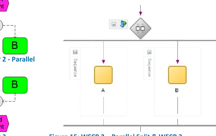
5.4.2 Diagram 2: WFCP 2 – Parallel Split & WFCP 3 - Synchronization ... 56
5.4.3 Diagram 3: WFCP 4 – Exclusive Choice & WFCP 5 – Simple Merge ... 57
5.4.4 Diagram 4: WFCP 6 – Multi Choice & WFCP 7 – Synchronizing Merge ... 59
5.4.5 Diagram 5: WFCP 11 – Implicit Termination ... 61
5.4.6 Diagrams 6 and 7: WFCP 10 – Arbitrary Cycles ... 62
5.5 Conclusion of pattern transformation ... 63
6 Validation: a composite case from practice ... 65
6.1 Case description: “Accounting close” ... 65
6.2 Transforming individual sub-processes... 67
6.3 Diagram 8: Prepare accounting close ... 67
6.5 Diagram 10: Check final hour download ... 68
6.6 Diagram 11: Preliminary rebilling ... 69
6.7 Diagram 12: Update report data ... 69
6.8 Diagram 13: Report ... 70
6.9 Diagram 14: Full composite diagram – Accounting close ... 70
6.10 Conclusion of case transformation ... 71
7 Guidelines for modeling ... 73
7.1 Criteria ... 73
7.2 Limitation 1: Construct excess (OR-connector) ... 75
7.3 Limitation 2: Construct overload and redundancy ... 76
7.4 Limitation 3: Pattern incompatibility (WFCP 10 - Arbitrary Cycle) ... 77
7.5 Limitation 4: Multiple start events ... 78
7.6 Limitation 5: Degree of connectors ... 78
7.7 Limitation 6: Multiple end events ... 79
7.8 Limitation 7: Combination of constructs and structures ... 80
7.9 Limitation 8: Block-structured versus graph-structured ... 80
7.10 General guidelines ... 82
7.11 Applying the guidelines ... 82
7.12 Validation of the guidelines in the composite case ... 84
7.12.1 Applying the guidelines while modeling ... 84
7.12.2 Applying the guidelines to an existing model ... 85
8 Discussion ... 89
8.1 Validity ... 89
8.2 Limitations ... 90
8.4 Further Research ... 91
8.5 Recommendations ... 92
9 Conclusions ... 94
9.1 Answers to research sub-questions ... 94
9.2 Answers to main research questions ... 95
9.3 Contributions ... 97
1
Introduction
Due to globalization and economic crisis, companies feel an increased market pressure. In response, they look for new ways of improving their business processes. To achieve processes that are more efficient, several established approaches are available. Examples are Business Process Management (BPM), Business Process Engineering (BPE), and Business Process Reengineering (BPR). Each of these approaches has their own set of supporting tools. A recent initiative introduced an extra means to support the existing approaches, by making the improved business process executable. This new approach goes under the name of Model-Driven Engineering (MDE) (Kent, 2002). The central idea of MDE is that models can transform into other models. While this idea sounds trivial, it allows transformation from business process models to executable models. This research handles a specific case of this model-to-model transformation.
1.1
Background
1.1.1 The worlds of business and IT
This research classifies two separate worlds: The business world of the modelers, and the information technology (IT) world of the developers. This research defines the modelers as the people who create and manage the business process models. These models are their main artifacts. They are generally business architects, business modelers, requirements engineers, and process analysts. On the other hand, developers are the people who create and edit executable code and applications. The created code is their main artifact. Developers are generally programmers, software engineers, and software architects. While this is a coarse division, it serves the purpose of this research.
coding. If the tooling also supports round-trip engineering, then it allows continuous process improvement to take place, as is required from a BPM perspective (Smith & Fingar, 2003). MDE provides the promise of achieving the business demands.
From the IT world point of view, the demands of the business world often appear to be unreasonable. IT has to work within strict specifications, limited budget, and harsh deadlines. For developers, the constraints often mean that they compromise one of the three constraints to achieve the others. The concession results in either hurried, over-budget, or sub-standard projects. MDE automates a large part of the process, and provides clearer artifacts. This frees up budget and time for the developers. Furthermore, maintenance is often a significant cost driver, due to poor development in the past and frequent changes to systems. Applying MDE allows modelers to change the systems correctly according to the business process. This saves work on the implementation of changes by maintenance. In conclusion, MDE enables IT to achieve the demands of business.
1.1.2 Sogeti (and the two worlds)
This research was conducted on behalf of Sogeti Nederland B.V. Sogeti provides IT services to businesses and public-sector organizations. Sogeti employs about 18,000 employees, of which about 3,400 work in The Netherlands. It is a wholly owned subsidiary of the international Capgemini organization. Sogeti Nederland B.V. has a divisional structure. Two of these divisions are of particular interest to this research, as they correspond to the two worlds of IT and business.
The division Architecture & Business Solutions (A&BS) first looks at the business objectives of customers. Based on this, they examine which business processes, systems, and information the customers require. They use methodologies such as Architecture of Integrated Information Systems (ARIS) (Scheer & Schneider, 1992) and Dynamic Architecture (DYA) (Wagter, Van den Berg, Luijpers, & Van Steenbergen, 2001). As this division focuses on the business, its professionals are in the modeler category of the business world.
development platform. Their aim is to deliver maintainable, future proof systems, which match the customer’s demands. The professionals working for DSE represent the developers of the IT world.
1.1.3 Model transformation
MDE is an approach with many aspects. Of these aspects, this research focuses on model transformation. This resides at the heart of MDE. The specific type of model transformation under investigation is the transformation from Event-driven Process Chain (EPC) (Scheer & Schneider, 1992) models to Business Process Execution Language (BPEL) specifications (OASIS, 2003). EPC models are the notation of ARIS for the control flow of business processes. The business world uses these to model part of their business processes, using tools such as IDS Scheer’s Architect. BPEL is the de facto standard for orchestrating web services. The IT world uses BPEL to model and execute the control flow from web service to web service, for example in a Service Oriented Architecture (SOA). For this, they use tools such as Oracle’s JDeveloper, part of the Oracle SOA Suite.
For the direct transformation from EPC to BPEL, only two tools are available. These are the Oracle BPA Suite and IDS Scheer SOA Architect. The Oracle BPA Suite has the SOA Architect as basis, through an OEM license. Both tools have the same basis, but the Oracle BPA Suite is freely available in the form of an evaluation version. Therefore, this research uses only the Oracle BPA Suite for transformation.
The Oracle BPA Suite includes the Business Process Architect component. This component allows specifying business processes, using de facto standards, such as BPMN and BPEL, as well as the EPC models from ARIS. The product descriptions promise that, with a click on a button, transformation is possible from modeled EPC business processes to BPEL specifications (Oracle, 2008). From there, it is possible to generate, orchestrate, and execute web services, with the Oracle SOA Suite (Oracle, n.d.). Oracle claims that their SOA Suite and BPA Suite together are an integrated environment, enabling round-trip engineering.
1.2
Scope
transformation. The focus is on transforming EPC models to BPEL specifications, especially discovering the feasibility of automated transformation from EPC to BPEL. The model is put to the test in the Oracle BPA Suite, by transforming a series of diagrams. If any limitations and difficulties arise during transformation, then guidelines help the modeler to solve and avoid them. These guidelines improve the feasibility of model transformation. Together, these parts lead to a conclusion on the feasibility of the transformation of EPC models to BPEL specifications.
1.3
Outline
2
Research Design
As the research explores a single type of transformation within a single product, several choices are clear from the start. The research aims at providing a profound examination of the EPC to BPEL transformation, in a qualifying manner. Studying existing literature on related topics forms a basis. The basis is used to build a conceptual model as theoretical research. Empirical investigation tests this theory. Finally, guidelines are devised based on the results.
This chapter starts with a description of the research objective. Then, it specifies the research questions that require answers, in order to reach the research objective, as well as how to answer these questions. Finally, the chapter defines the materials used and explains the research strategy.
2.1
Research Objective
2.2
Research Questions
In order to reach the objectives of this research, several questions require answers. Each of the main research questions corresponds to a limited fraction of the research model (see section 2.3). When all main research questions are answered, the research objectives are reached.
1. To what extent is automated transformation from EPC models to BPEL specifications possible?
a. To what ontology must business process modeling languages adhere? b. Which business process patterns are commonly used in business processes? c. How do the constructs of each language relate to the patterns and ontology? d. How do the constructs map from EPC to BPEL in theory?
2. What are the effectiveness and the limitations of (partially) automated transformations from EPC models to BPEL specifications, as supported by the Oracle BPA Suite?
a. What are the known limitations of such transformations?
b. Which patterns, concepts, and constructs do not transform successfully? c. Are acceptable workarounds available for those cases?
3. What modeling guidelines must modelers follow, to enable (partially) automated transformations from EPC models to BPEL specifications, as supported by the Oracle BPA Suite?
a. What is the level of detail required for EPC diagrams, compared to that required by BPEL specifications?
b. What type of information must EPC models include before transformation can take place?
c. Are acceptable workarounds available for limitations that need them?
d. How must EPC models be structured (e.g. composed of patterns and avoid patterns) to allow transformation?
e. Is such a structuring acceptable?
chapters 5 and 6 reveal limitations. Confronting the empirical results to the conceptual criteria provides the evaluation of question 2. Finally, chapter 7 prescribes the guidelines that the last question asks for, based on the earlier findings. The remaining chapters discuss and conclude the overall findings, and evaluate the research.
2.3
Research Model
In order to conduct the research successfully, a research model is formulated. Figure 1 provides a visual representation of this model. The following paragraphs specify a textual interpretation (Verschuren & Doorewaard, 1998).
[image:19.595.74.526.272.617.2]The research starts with a review of selected literature on modeling. The focal points are workflow patterns and ontology: the basis for the criteria. Further literature includes model transformation, MDE, and the two modeling languages. Furthermore, documentation of the chosen tool, Oracle BPA Suite, is inspected. The literature review leads to a selection of commonly used business process patterns and an ontological foundation, on which to compare EPC to BPEL. The two sources together compose the criteria, on which to judge the
effectiveness of transformation from EPC models to BPEL specifications. Known issues are collected from literature. The tool’s own specifications supplement the known issues. Possible workarounds provided in the literature are used to devise guidelines for modeling. The known issues and standard business process patterns both act as a starting point to create small EPC diagrams. In addition to the small diagrams, a larger, real-life case is used, composed of as many of the standard patterns as reasonable. The whole set of diagrams is transformed from EPC to BPEL specifications using the Oracle BPA Suite. Limitations and difficulties of the transformation are detected by comparing the resulting specifications to the original models. Confronting the limitations to the desired criteria set previously supplies a conclusion on the effectiveness of the transformation. Combining the limitations with possible workarounds leads to a set of guidelines, which modelers can apply to improve automated transformation.
2.4
Material for Investigation
BPA Suite. For the final main research question, the analysis of the experiment is most important in devising guidelines for modeling. Existing workarounds and guidelines are taken from the documentation of the Oracle BPA Suite and literature on model transformations. This literature functions to review the acceptability of the guidelines. Table 1 lists the material, in combination with the sub-questions that require it.
2.5
Research Strategy
The research as a whole consist of three parts, as divided by the research objectives and questions. The first two parts are explanatory and predictive in nature (Gregor, 2006). At first, analyzing the content of prior literature and documentation establishes a general theoretical model on transformation. The model consists of criteria based on both ontology and workflow patterns. Basing the research on a stable foundation supports the theoretical soundness and avoids duplicating previous research. The theoretical model explains and predicts the features of model transformation. Secondly, in order to prove the established theory in practice, conducting an experiment produces empirical results. The experiment consists of the construction and transformation of process patterns. The patterns are constructed as EPC diagrams, according to the criteria learned from literature. The Oracle BPA Suite transforms the selected diagrams into BPEL specifications. The results of the experiment include the output specifications and any errors encountered. The results are analyzed to evaluate the effectiveness of the transformation by considering the, severity of, limitations and possible workarounds. Selecting and analyzing the patterns happens in a hierarchical fashion, where the different patterns are first constructed, transformed, and
Table 1: Research material
Sources Questions
Documentation Language specifications
1c, 1d, 3a
BPA Suite 2a, 3a
Experiment Input/Output/Result 2b
Analysis 3a, 3b, 3c
Literature Workflow patterns 1b, 1c, 2b, 2c, 3d
Model
transformation
1d, 2a, 2c, 3c, 3a, 3b, 3c, 3d, 3e
3
Related research
This chapter provides an overview of existing literature related to this research. It begins with elaborating the criteria, based on which to evaluate the model transformation. The conceptual model in chapter 4 uses these criteria, which originate from ontology (section 3.1) and workflow patterns (section 3.2). For the same chapter, sections 0 and 3.4 introduce EPC and BPEL as the two modeling languages. Before dealing with the main subject of this research, section 3.5 introduces Model-Driven Engineering, to provide a background for the whole research. Model transformation is one of the key issues within MDE, and as the focal point of this research, section 3.6 investigates it next. Then, section 3.7 treats the tool that actually transforms from EPC to BPEL, the Oracle BPA Suite. Chapters 5 and 6 use it to obtain empirical results. Finally, section 3.8 draws some conclusions based on the literature. Together, these subjects cover all aspects of the research.
3.1
Ontology
In general, ontology is a branch of metaphysics concerned with the nature of being. Metaphysics, in turn, is the philosophy concerned with abstract concepts, such as the nature of existence or of truth and knowledge (Soanes & Hawker, 2005). It is the discipline concerned with theories of how the "world" may be viewed, conceived, or modeled (Falkenberg, et al., 1998). As part of this research, ontology provides a theoretical foundation, as it studies the way the world, in this case business processes, is viewed, and especially modeled.
3.1.1 Ontology for information systems
The specific ontology applied is the BWW model. It is an adoption of Bunge’s ontology (Bunge, 1977, 1979), specifically adapted for information systems by Wand and Weber (Wand & Weber, 1990). In the view of Bunge (1977), ontology is an attempt to categorize, in order to provide a mutual base for understanding. While two parties may agree to disagree, at least they agree on what they disagree. For modeling, this means anything can be expressed by a certain set of concepts, an ontology, and that agreement can be reached on these concepts. For example, in the case of EPC, two business analytics may disagree on the exact form of the business process (do we need an AND-split or an OR-split in this place in the process), but at least the notation (events, functions, arcs, and connectors) is agreed upon.
Wand and Weber (1990) view an information system as a model (abstract artifact) of a real-world system, as viewed by an individual. Information system development, in turn, is the transformation of this individuals view to the artifact (the information system) itself. They aim to specify the quality of the transformation from the individual’s view to the artifact. In simpler words: How good the representation is.
3.1.2 The choice for the BWW model
The choice for the BWW model is not without argument. The Scandinavian Journal of Information Systems (2006) published a debate on the BWW model. The main criticisms given in this debate (Wyssusek, 2006), include that the BWW model lacks ontological commitment, Bunge’s ontology is inappropriately used as a language, conceptual modeling is by definition not captured in ontology, and Wand and Weber missed or ignored several relevant parts. Both Wand and Weber, and other respected researchers provided their view on the critique (Wand & Weber, 2006). They managed to put aside these criticisms, although the debate remains open.
Other ontologies, not BWW or even based on Bunge (for example the ideas of Guizzardi (2005)) or completely different evaluation approaches may be more suitable for analyzing models. Illustrative of this issue is that Wand and Weber (2006) themselves welcome suggestions about other ontologies that may be better in providing a foundation for conceptual modeling. Criteria for an applicable ontology are already described (Gehlert & Esswein, 2007). Still, this research uses the BWW model as one of the two criteria. This choice is based on general acceptance in the field of information systems, theoretical foundation, and extent of available literature on the BWW model. The following paragraphs further elaborate these points.
The general acceptance of the BWW model is demonstrated by the amount of research that empirical validated the model (Bodart, Patel, Sim, & Weber, 2001) (Gemino & Wand, 2005) (Parsons & Cole, 2005) (Burton-Jones & Meso, 2006) and as it is the one generally used in similar cases. For example, it was used to assign semantics to UML (Everman & Wand, 2001), evaluate UML (Opdahl & Henderson-Sellers, 2002), design an approach to evaluate reference models (Fettke & Loos, 2003), analyze the five views of ARIS (Green & Rosemann, 2000), and compare process modeling techniques (including BPEL and EPC) (Rosemann, Recker, Indulska, & Green, 2006).
of formalization and has a standard notation. Lastly, Bunge firmly rooted his ideas on prior ontological research.
More literature focused on deriving new artifacts from the BWW model. In relation to th research, several articles handled the evaluation of conceptual models by using the BWW model, including giving a framework of conceptual modeling
method to validate conceptual models and pitfalls for conceptual modeling
3.2
Workflow patterns
A second approach to evaluate and compare modeling languages to other languages,
identified in architecture 1977). The style applied there Johnson, & Vlissides, 1995)
literature, specifically the patterns by Van Aalst et al. Barros, 2003) (Aalst, Barros, Hofst
patterns for control flow, resources
(Russell N. , Hofstede, Edmond, & Aalst, 2005) Hofstede, 2006)
only deal with static flow of control, only static workflow control patterns (WFCP, further use of patterns refers to these specific patterns, unless explicitly stated otherwise) are the patterns considered as criteria for this research.
patterns.
3.2.1 The source for patterns
[image:26.595.111.467.584.624.2]The original source for patterns 20 patterns. The patterns flow (patterns 1
Figure 2: Example pattern using CP
of formalization and has a standard notation. Lastly, Bunge firmly rooted his ideas on prior ontological research.
More literature focused on deriving new artifacts from the BWW model. In relation to th research, several articles handled the evaluation of conceptual models by using the BWW model, including giving a framework of conceptual modeling
method to validate conceptual models (Shanks, Tansley, & Weber, 2003) and pitfalls for conceptual modeling (Weber, 2003)
Workflow patterns
A second approach to evaluate and compare modeling languages
to other languages, is to identify their support for patterns. Patterns in general were first identified in architecture (Alexander, Ishikawa, Silverstein, Jacobson, Fiksdahl
. The style applied there was copied for use in other areas, including IT
Johnson, & Vlissides, 1995). For this research, the applicable patterns appear in workflow literature, specifically the patterns by Van Aalst et al.
(Aalst, Barros, Hofstede, & Kiepuszewski, 2000)
patterns for control flow, resources (Russell, Aalst, Hofstede, & Edmond, 2004) (Russell N. , Hofstede, Edmond, & Aalst, 2005)
Hofstede, 2006). Both dynamic and static patterns were identified. As both EPC and BPEL only deal with static flow of control, only static workflow control patterns (WFCP, further atterns refers to these specific patterns, unless explicitly stated otherwise) are the patterns considered as criteria for this research.
The source for patterns
The original source for patterns (Aalst, Hofstede, Kiepuszewski, & Barros, 2003) 20 patterns. The patterns fall into categories, ranging
flow (patterns 1-5), advanced branching and synchronization (6
: Example pattern using CP nets (from www.wo
of formalization and has a standard notation. Lastly, Bunge firmly rooted his ideas on prior
More literature focused on deriving new artifacts from the BWW model. In relation to th research, several articles handled the evaluation of conceptual models by using the BWW model, including giving a framework of conceptual modeling (Wand & Weber, 2002)
(Shanks, Tansley, & Weber, 2003), and possibilities (Weber, 2003).
A second approach to evaluate and compare modeling languages, as well as their mappings is to identify their support for patterns. Patterns in general were first
(Alexander, Ishikawa, Silverstein, Jacobson, Fiksdahl
copied for use in other areas, including IT (Gamma, Helm, . For this research, the applicable patterns appear in workflow literature, specifically the patterns by Van Aalst et al. (Aalst, Hofstede, Kiepuszewski, & ede, & Kiepuszewski, 2000). They defined workflow
(Russell, Aalst, Hofstede, & Edmond, 2004) (Russell N. , Hofstede, Edmond, & Aalst, 2005), and exception handling (Russel, Aalst, &
. Both dynamic and static patterns were identified. As both EPC and BPEL only deal with static flow of control, only static workflow control patterns (WFCP, further atterns refers to these specific patterns, unless explicitly stated otherwise) are the patterns considered as criteria for this research. Figure 2 provides an example
(Aalst, Hofstede, Kiepuszewski, & Barros, 2003) fall into categories, ranging from simple to complex: basi 5), advanced branching and synchronization (6-10), structural (11
nets (from www.workflowpatterns.com)
of formalization and has a standard notation. Lastly, Bunge firmly rooted his ideas on prior
More literature focused on deriving new artifacts from the BWW model. In relation to this research, several articles handled the evaluation of conceptual models by using the BWW (Wand & Weber, 2002), a , and possibilities
, as well as their mappings is to identify their support for patterns. Patterns in general were first (Alexander, Ishikawa, Silverstein, Jacobson, Fiksdahl-King, & Angel, (Gamma, Helm, . For this research, the applicable patterns appear in workflow (Aalst, Hofstede, Kiepuszewski, & . They defined workflow (Russell, Aalst, Hofstede, & Edmond, 2004), data (Russel, Aalst, & . Both dynamic and static patterns were identified. As both EPC and BPEL only deal with static flow of control, only static workflow control patterns (WFCP, further atterns refers to these specific patterns, unless explicitly stated otherwise) are the provides an example of one such
(Aalst, Hofstede, Kiepuszewski, & Barros, 2003) considered from simple to complex: basic control 10), structural (11-12),
multiple instance (13-16), temporal (17), state-based (18), and cancelation patterns (19-20). In parallel to architectural patterns (Alexander, Ishikawa, Silverstein, Jacobson, Fiksdahl-King, & Angel, 1977), each pattern has a description, synonyms, and examples. The complex cases include the problem (why it is hard to realize) and a possible implementation strategy. As criteria for transformation, only those patterns that EPC can model are applicable as criteria.
The first set of patterns was later complemented. A new article added four advanced patterns (Aalst, Barros, Hofstede, & Kiepuszewski, 2000). Besides workflow control patterns, the previously mentioned data, resource, and operational patterns were defined. Additionally, several new patterns were conceived and recorded. A more recent article introduces many extra patterns, including relations between the patterns (Russell N. , Hofstede, Aalst, & Mulyar, 2006). The complete set of (known) patterns resides at http://www.workflowpatterns.com (which Van Aalst and Ter Hofstede maintain).
3.2.2 Evaluation of patterns
The patterns were researched in a number of ways. Formal definitions of the patterns were given in relation to three evaluation strategies languages use: standard, safe (subset of standard based on or-join behavior), and synchronized (avoids arbitrary cycles and thus deadlocks) (Kiepuszewski, Hofstede, & Aalst, 2003). In order to verify and validate the patterns, they were transformed to Colored Petri Nets (Mulyar & Aalst, 2005). Additionally, the patterns were drawn on, to specify a Workflow Pattern Specification Language (Mulyar, Aalst, Hofstede, & Russell, 2006). With the aim to rank the patterns, two studies were conducted on the use of the patterns in practice (Vries & Ommert, 2001) (Vries & Ommert, 2002). The above research improved the knowledge on patterns widely.
3.2.3 Application
modeling languages, including U
BPMN (Wohed, Aalst, Dumas, Hofstede, & Russell, 2006) Nüttgens, 2005)
leaves the comparison of the two languages, EPC and BPEL, according to the patterns, for this research.
3.3
Event-driven Process Chain (EPC)
Event-driven Process Chains (EPC) is a business process modeling language, developed to model the control flow of business processes (Keller, Nüttgens,
of EPC are functions, events, connectors, and arcs. exception of arcs (arrows),
Functions are the elemental activities in a business process triggers each function
always alternate, similar to places and transitions in Petri represent the control flow through the model
other. Connectors split and join t the AND-, OR-, and XOR
block-based, such as BPEL. and semantics (Aalst, 1999) 3.3.1 History
Originally developed
in ARIS, EPC represents the center of the
ARIS-House of Business Engineering
& Schneider, 1992)
four other aspects of the ARIS architecture use different modeling languages to present their information.
different models of the ARIS produces a holistic
It established this reputation thanks to its application in both the ARIS toolset and SAP, who modeling languages, including UML (Wohed, Aalst, Dumas, Hofstede, & Russell, 2005)
(Wohed, Aalst, Dumas, Hofstede, & Russell, 2006)
ttgens, 2005), and BPEL (Wohed, Aalst, Dumas, & Hofstede, 2003)
leaves the comparison of the two languages, EPC and BPEL, according to the patterns, for
driven Process Chain (EPC)
driven Process Chains (EPC) is a business process modeling developed to model the control flow of business (Keller, Nüttgens, & Scheer, 1992). The basic elements are functions, events, connectors, and arcs.
exception of arcs (arrows), Figure 3 shows the constructs. ns are the elemental activities in a business process
triggers each function, and each function leads to a new event itself always alternate, similar to places and transitions in Petri represent the control flow through the model
Connectors split and join the control flow. The EPC language has splits and joins of , and XOR-connector types. EPC is a graph
based, such as BPEL. Mapping the basic elements to Petri (Aalst, 1999).
History
developed for business processes represents the center of the
House of Business Engineering (Scheer
& Schneider, 1992), shown in Figure 4. The ther aspects of the ARIS architecture use different modeling languages to present their information. Coupling the different models of the ARIS-house
a holistic, yet complex, view. EPC is a
[image:28.595.108.521.486.713.2]It established this reputation thanks to its application in both the ARIS toolset and SAP, who
Figure
(Wohed, Aalst, Dumas, Hofstede, & Russell, 2005) (Wohed, Aalst, Dumas, Hofstede, & Russell, 2006), EPC (Mendling, Neumann, &
(Wohed, Aalst, Dumas, & Hofstede, 2003). The prior research leaves the comparison of the two languages, EPC and BPEL, according to the patterns, for
driven Process Chain (EPC)
driven Process Chains (EPC) is a business process modeling developed to model the control flow of business The basic elements are functions, events, connectors, and arcs. With the shows the constructs.
ns are the elemental activities in a business process. An internal or external leads to a new event itself. Events and functions always alternate, similar to places and transitions in Petri nets. Directed
represent the control flow through the model, attach the functions and events to each he control flow. The EPC language has splits and joins of connector types. EPC is a graph-based language, as opposed to Mapping the basic elements to Petri nets formalized their syntax
is a popular business process modeling language. It established this reputation thanks to its application in both the ARIS toolset and SAP, who
Figure 3: EPC constructs
Figure 4: Five views of ARIS
(Wohed, Aalst, Dumas, Hofstede, & Russell, 2005), (Mendling, Neumann, & . The prior research leaves the comparison of the two languages, EPC and BPEL, according to the patterns, for
n internal or external event vents and functions irected arcs, which , attach the functions and events to each he control flow. The EPC language has splits and joins of age, as opposed to ets formalized their syntax
popular business process modeling language. It established this reputation thanks to its application in both the ARIS toolset and SAP, who
adopted it to model their workflows. EPC is chosen for this research because of the popularity it has among business analysts as a business process modeling language, while it nevertheless has little attention for use in execution of business processes by IT.
3.3.2 (Non-) local semantics
The semantics of the join are a particular issue for EPC. Local semantics for the XOR-join were proposed first (Rittgen, 1999) (Aalst, 1999). More recently, non-local semantics were proposed (Nüttgens & Rump, 2002) (Kindler, 2006) (Cuntz & Kindler, 2005). Non-local semantics imply that a join locks when one branch reaches the join. If another branch also ends (for example after an AND- or OR-split), then the join does not continue again. Similarly, the OR-join has non-local semantics in EPC too. After an OR-join, the next step only executes when all activated branches have reached the join.
3.3.3 Extensions
Several extensions to EPC were proposed. These proposals include modified EPC (modEPC) (Rittgen, 1999), extended EPC (eEPC) (Scheer, 1994), and YAWL EPC (yEPC) (Mendling, Neumann, & Nüttgens, 2005). Each of these extensions has its own use. The first extension was an attempt to provide formal semantics for EPC. It led to modEPC, which tries to retain the understandability of EPC, while having rigorous formal semantics. The second extension, eEPC, is applied in practice most often. As its name implies, it extends the functionality of EPC for business processes. For example, SAP uses it currently to model the control flow. The last extension came from the area of workflow patterns (see section 3.1). EPC was adapted to YAWL (Yet Another Workflow Language) (Aalst & Hofstede, 2005), so it could represent all workflow patterns. This research considers only classical EPC, as this is what the tool supports.
3.4
Business Process Execution Language (BPEL)
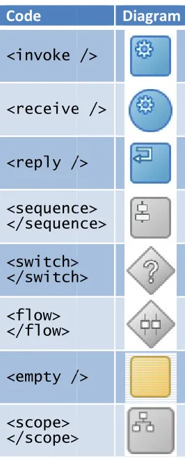
communication occurs through partnerLinks. examples of some constructs
2007) references all constructs
3.4.1 History
BPEL is an eXtensible Markup Language (XML) based language. As the name implies, it is aimed at making business processes executable. Its first
combination of Microsoft’s execution language XLANG and IBM’s execution language WSFL. Shortly after
and the second version (1.1)
in use now, was submitted to the standards body OASIS and approved as an official, open standard. Currently
version is 2.0 (OASIS, 2007) version includes m
behind (OASIS, 2007) 3.4.2 Issues
BPEL was created to accommodate both the internal, executable view of processes, in addition to the external, abstract view
used (Aalst, Dumas, Hofstede, Russell, Verbeek, & Wohed, 2005)
lies in the power BPEL has to be executable, which makes it a hard language to learn. The targeted users for the abstract portion, business modelers, prefer to stick to languages in which they are able to easier and better expre
example, Business Process Modeling Notation (BPMN)
and EPC. The BPEL specification does not impose any graphical representation or design methodology for the processes modeled in it.
different representations, possibly leading to confusion. Some tried to use BPMN as the notation for BPEL. However, the attempts drew attention to various incompati
between executable specifications and abstract models Formal semantics are not yet complete
(Green & Rosemann, 1999)
communication occurs through partnerLinks.
examples of some constructs. The official specification references all constructs.
History
is an eXtensible Markup Language (XML) based language. As the name implies, it is aimed at making business processes executable. Its first specification (1.0) was built in 2002 as a combination of Microsoft’s execution language XLANG and IBM’s execution language WSFL. Shortly after,
and the second version (1.1) (OASIS, 2003), which is commo , was submitted to the standards body OASIS and approved as an official, open standard. Currently
(OASIS, 2007), which was approved in 2007. version includes many improvements, but tool support still lag
(OASIS, 2007).
BPEL was created to accommodate both the internal, executable view of processes, in addition to the external, abstract view (OASIS, 2007)
(Aalst, Dumas, Hofstede, Russell, Verbeek, & Wohed, 2005)
lies in the power BPEL has to be executable, which makes it a hard language to learn. The targeted users for the abstract portion, business modelers, prefer to stick to languages in which they are able to easier and better expre
example, Business Process Modeling Notation (BPMN)
The BPEL specification does not impose any graphical representation or design gy for the processes modeled in it.
different representations, possibly leading to confusion. Some tried to use BPMN as the notation for BPEL. However, the attempts drew attention to various incompati
between executable specifications and abstract models
Formal semantics are not yet complete (Reichert & Rinderle, 2006) (Green & Rosemann, 1999) (Wohed, Aalst, Dumas, & Hofstede, 2003)
Table 2 provides he official specification (OASIS,
is an eXtensible Markup Language (XML) based language. As the name implies, it is aimed at making business processes specification (1.0) was built in 2002 as a combination of Microsoft’s execution language XLANG and , others joined in , which is commonly , was submitted to the standards body OASIS and approved as an official, open standard. Currently, the newest approved in 2007. This s, but tool support still lags
BPEL was created to accommodate both the internal, executable view of processes, in IS, 2007). In practice, the abstract view is hardly (Aalst, Dumas, Hofstede, Russell, Verbeek, & Wohed, 2005). The cause for lack of use lies in the power BPEL has to be executable, which makes it a hard language to learn. The targeted users for the abstract portion, business modelers, prefer to stick to languages in which they are able to easier and better express themselves. These languages include, for example, Business Process Modeling Notation (BPMN) (Object Management Group, 2008)
The BPEL specification does not impose any graphical representation or design gy for the processes modeled in it. Consequently, different tool vendors different representations, possibly leading to confusion. Some tried to use BPMN as the notation for BPEL. However, the attempts drew attention to various incompati
[image:30.595.393.526.90.420.2]between executable specifications and abstract models (Recker & Mendling, 2006) (Reichert & Rinderle, 2006). BPEL (Wohed, Aalst, Dumas, & Hofstede, 2003) and
Table 2: BPEL constructs
Code <invoke /> <receive /> <reply / <sequence> </sequence> <switch> </switch> <flow> </flow> <empty /> <scope> </scope>
BPEL was created to accommodate both the internal, executable view of processes, in the abstract view is hardly . The cause for lack of use lies in the power BPEL has to be executable, which makes it a hard language to learn. The targeted users for the abstract portion, business modelers, prefer to stick to languages in These languages include, for (Object Management Group, 2008) The BPEL specification does not impose any graphical representation or design ifferent tool vendors have different representations, possibly leading to confusion. Some tried to use BPMN as the notation for BPEL. However, the attempts drew attention to various incompatibilities
(Recker & Mendling, 2006).
. BPEL was analyzed and compared to
: BPEL constructs
other languages (Shapiro, 2002) (Söderström, Andersson, Johannesson, Perjons, & Wangler, 2002). Several attempts cover the semantics of a limited number of elements (Reichert, Rinderle, & Dadam, 2004). One of the things that received adequate attention is the control flow (Ouyang, Verbeek, Aalst, Breutel, Dumas, & Hofstede, 2007). As this research focuses on the transformation of the control flow, it suffices that the control flow semantics are formalized.
3.4.3 Web services
For web services, BPEL is the de facto standard as orchestration language. It describes when to call which service. In addition to using standard XML technology, such as XPath, BPEL closely relates to WSDL and SOAP. BPEL uses WSDL to specify message and port types, both for web services it communicates to, and to specify itself as a web service. BPEL makes use of SOAP as a messaging protocol. Together with UDDI, for discovery and publishing, these standards provide a basis for web services and service oriented architecture (SOA).
3.4.4 Versioning
The primer, which accompanies the BPEL version 2.0 specifications (OASIS, 2007), documents the differences between the BPEL versions. In short, the main improvements are improved data access with XPath, extension possibilities, extra scope options, new structure activities, clearer names for some old activities, adaptation and formalization of some proprietary extensions, and clarified usage of abstract processes.
3.5
Model-Driven Engineering (MDE)
define methodologies, develop systems at any level of abstraction, and organize testing and validation (Fondement & Silaghi, 2004).
3.5.1 History
Kent (2002) coined the term Model-Driven Engineering (MDE). However, its history starts earlier. Kent’s starting point was the Model-Driven Architecture (MDA), which he defined as an instance of MDE. With MDE, he tried to fill the gap left by MDA. Extra dimensions were introduced, mainly borrowed from Aspect Oriented Software Development. MDA is a registered trademark from the Object Management Group (OMG), who established it in 2001 as a base architecture. It is the most widely known form of MDE. MDA aims to achieve architectural separation of concerns in a four-step approach. The first step is to design the business process as a Computation Independent Model (CIM), which describes how the system fits in its domain. The second step devises a Platform Independent Model (PIM), according to the CIM. The PIM specifies the system itself, without advancing to platform specific implementation details. The third step creates a Platform Specific Model (PSM) through, preferably automated, transformation from the PIM. Finally, the PSM is converted to an executable implementation, which happens through, once again preferably automatic, transformation. Together, these four steps complete the route from (business) model to code (Object Management Group, 2003). MDE can be viewed as a continuation from Computer Aided Software Engineering (CASE) tools, which have been used from the eighties onwards.
3.5.2 Levels of abstraction
MDE provides modelers with the ability to work at different levels of abstraction. It provides this ability by taking the view that, “everything is a model” (adjusted for MDE from the object-oriented “everything is an object”) (Bézivin, 2004). This view permits source code, as
Table 3: A couple of acronyms related to MDE
MDA Model Driven Architecture MDD Model Driven Development MDE Model Driven Engineering
MDSD Model Driven Software Development MDSE Model Driven Software Engineering
well as conceptual models, to be seen as models, in turn allowing model transformation along the entire process chain of software and system development.
Models exist at different levels of abstractions. Two dimensions for abstraction of models exist, one focusing on use of the model and the other on definition of the model. The first dimension is the obvious difference between the source code and any other model of the business process. Here it is clear that any subsequent business process model is more abstract, in order to be easier to understand or be applicable to more situations. The second dimension is the way models are defined. This dimension is presented in a four level architecture (Object Management Group, 2003), as depicted in Table 4. A model (M1) represents the real world (M0). A model is written in a certain modeling language (M2, model). A model (M3) describes the modeling language. Finally, the meta-meta-model also describes itself. This is of utmost importance for model transformations, as the ability to transform between different models depends on the clear definition of the modeling constructs used.
3.5.3 Round-Trip Engineering
As was already noticed in the eighties in the case of CASE tools, models have the tendency to get out-of-sync with the system. The cause for this problem is that the system is developed, without updates to the model, leading to maintenance problems. (Imagine the real life case, where a water pipeline is demolished, because a new road is constructed based on outdated infrastructural charts, which do not include the pipeline yet.) To avoid similar problems, not only transformation of models to (a representation closer to) source code must take place (also known as forward engineering), but also reverse engineering to update (abstract) models based on changes in concrete models, such as source code. This combination of reverse and forward engineering is known as round-trip engineering. It is
Table 4: MDA "3+1"-level Architecture
Level Name Description Example
M3 Meta-meta-model A language to define a modeling language. Includes defining itself.
MOF
M2 Meta-model A modeling language. EPC; BPEL
M1 Model The model itself. A process model “BP”
more than a sequence of forward and reverse engineering, as the representations must stay synchronized. Information “lost” during the initial action, must be recoverable by the reverse action. Round-trip engineering enables modelers and developers to work on the same artifact, at different levels of abstraction. Round-trip engineering, consequently, facilitates the desirable separation of concerns (Sendall & Küster, 2004).
3.6
Model transformation
In this research, model transformation corresponds to the transfer of a model from one modeling language (meta-model) to another. From the MDE point of view that everything is a model, this also includes the transformation to and from source code (Bézivin, Farcet, Jézéquel, Langlois, & Pollet, 2003). Thus, in contrast to (Alanen, Lilius, Porres, & Truscan, 2003) and sticking to MDA (Object Management Group, 2003), no distinction is made between model-to-model and model-to-code transformation. Transforming toward a more concrete model (for example code) is called forward engineering, while going toward a more abstract model is called reverse engineering. The specific focus is on mapping transformations, where each element of a source model maps to zero, one, or more elements in a target model (Alanen, Lilius, Porres, & Truscan, 2003). As opposed to update transformations, mapping transformations do not alter the source model. A classification of model transformation approaches was proposed (Czarnecki & Helsen, 2003). While transformation of models within a language is possible, this research only considers transformation of models between two languages, namely EPC to BPEL as provided by the Oracle BPA Suite.
code-to-code, the first code already is an abstraction from machine code. Machine code-to-code, in turn, is an abstraction (model) of bits and bytes. The history shows that what was previously deemed hard, impossible, or a typical human activity is now standard an automated process. The model transformation under consideration is regarded as a next step in “model becomes code”.
Much research on model transformation has been conducted already. For sake of brevity, the section discusses only studies on transformation to BPEL and on transformation from EPC. Some transformations that do not fit in these two categories but are still of interest, include the transformation of graph-structured to block-structured diagrams (Mendling, Lassen, & Zdun, 2007) (Mendling, Lassen, & Zdun, 2006), and the reverse engineering of BPEL to EPC (Mendling & Ziemann, 2005).
3.6.1 Transforming to BPEL
Within the first category, the predominant transformation investigated is from BPMN to BPEL. The aim of BPMN stated in its specification, to provide a visualization for BPEL (Object Management Group, 2008), stirs the interest for this transformation. The BPMN specification, as well as other work by one of the authors of the original specification, specified a simple mapping (White, 2005). However, when trying to formalize the transformation several researchers ran into complications (Recker & Mendling, 2006) (Ouyang, Aalst, Dumas, & Hofstede, 2006) (Srikarsemsira & Roongruangsuwan, 2005). The problems found, include the difficulty of mapping a graph structure to a block structure, loss and lack of data, ontological (domain representation) mismatch, and pattern (process representation) mismatch. Workarounds and improvements for some of these problems were formulated (Hauser & Koehler, 2004) (Ouyang, Aalst, Dumas, & Hofstede, 2006) (Ouyang, Dumas, Aalst, & Hofstede, 2006). Other transformations to BPEL studied, include mappings from workflow nets (Aalst & Lassen, 2005), Petri nets (Koschmider & Mevius, 2005) (and reverse (Hinz, Schmidt, & Stahl, 2005)), UML (Gardner, 2003), and even from requirements to BPEL via colored workflow nets (Aalst, Jorgensen, & Lassen, 2005).
3.6.2 Transforming from EPC
and verification tools are readily available for Petri nets. A transformation of private, internal EPC diagrams to public, external BPMN diagrams is explained, to improve business collaboration (Hoyer, Bucherer, & Schnabel, 2008). A (partial) transformation to UML is also elaborated, in order to link business processes to object orientation (Nüttgens, Feld, & Zimmermann, 1998).
3.6.3 Transforming from EPC to BPEL
Finally, the transformation that is most interesting to this research, involves both categories: from EPC to BPEL transformation. Two research articles were located on the subject. One is an article by authors of IDS Scheer (Stein & Ivanov, 2007). They provided a ten-step approach, from modeling to implementation and testing, for the transformation of EPC to BPEL for SOA. The approach includes the input of four different human roles. The other article is from the same authors who published the BPEL to EPC transformation mentioned above (Ziemann & Mendling, 2005). They provided a conceptual mapping from EPC to BPEL, based on the five limiting assumptions in Table 5. These assumptions are required, as EPC is more abstract than BPEL.
3.7
Oracle BPA Suite
The Oracle Business Process Analysis (BPA) Suite contains one of the solutions for transformation. For this research, the Oracle BPA Suite is chosen as transformation tool, as it is the only tool accessible providing EPC to BPEL transformation. Besides EPC to BPEL, it is also capable of BPMN to BPEL transformation. The Oracle BPA Suite is based on an OEM agreement for the ARIS Design Platform from IDS Scheer (Oracle, 2006). It combines the capacity of execution and monitoring of Oracle, with the strength of business modeling of IDS Scheer. Oracle offers the Suite as a component of Oracle Fusion Middleware. Besides modeling business processes, it also provides simulation and publishing of the process models.
Table 5: EPC to BPEL transformation assumptions
1 No new, BPEL specific, EPC constructs
2 Technical information has to be added, but control flow is complete 3 A BPEL activity relates to an event + function in EPC
3.7.1 Components
The Oracle BPA Suite contains several components. For this research, the vital component is the Business Process Architect, wherein it is possible to specify business processes. Using on one hand, de facto standards, such as BPMN and BPEL, and, on the other hand, the EPC models from ARIS (Oracle, 2008) (Oracle, n.d.). This component is also able to simulate the business processes. Besides process modeling and simulation, the Business Process Architect provides transformation. This research does not use the other components. Table 6 lists all components (Oracle, 2006).
3.7.2 Integration
Oracle believes that BPEL provides an important building block for Service Oriented Architectures
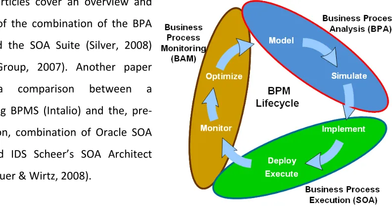
(SOA) (Oracle, 2006). Together with the Oracle SOA Suite, the Oracle BPA Suite is claimed to be an integrated environment, enabling round-trip engineering (“closed-loop BPM” in Oracle’s terms) (Oracle, n.d.). To enable this, Oracle attempts to adhere to standards. In the case of this research, the most important standard is BPEL. The integration of the BPA Suite and the SOA Suite happens in the three steps depicted in Table 7. The process is iterative, with the business model as master: the business (analyst) owns the model. In order to support the full extent of Oracle’s BPM Lifecycle (see Figure 5, on the next page), use is made of the existing coupling within the SOA Suite (for example BAM for monitoring, and the BPEL engine for execution) (Oracle, 2006).
Table 6: Oracle BPA Suite components
Component Description Business Process
Architect
Standards-based tool for process modeling. It uses various standards-based notations such as BPMN and EPC.
Business Process Repository Server
Server component for storing and sharing the process repository across multiple users in a collaborative environment
Business Process Simulator
Tool that simulates the process models based on a set of discrete events, to do "what if" analysis.
Business Process Publisher
Publishes process models to a large audience outside the core team designing the process models
Oracle Extensions for SOA
Allows bi-directional integration with the Oracle SOA Suite.
Table 7: Three step integration
Step 1 Business process modeling Step 2 Convert to Blueprint
Several articles cover an overview and analysis of the combination of the BPA Suite and the SOA Suite (Silver, 2008) (Butler Group, 2007). Another paper treats a comparison between a competing BPMS (Intalio) and the, pre-integration, combination of Oracle SOA Suite and IDS Scheer’s SOA Architect (Scheithauer & Wirtz, 2008).
3.8
Discussion of treated literature
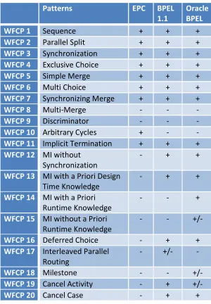
[image:38.595.118.514.78.289.2]As can be concluded from the above, model transformations are at the core of MDE. It is possible to evaluate modeling languages based on their ability to represent real world concepts (ontology) and their ability to form certain patterns. A model transformation is theoretically feasible depending on those criteria. The two modeling languages, EPC and BPEL, are compared based on the BWW representational model and 20 workflow control patterns. Issues for model transformation are anticipated, due to mismatches found in the ontology and pattern comparison, as well as due to the graph-to-block structure transformation and different levels of abstraction. The specific transformation for this research is a model-to-model mapping transformation of (abstract) classical EPC to (concrete) BPEL 1.1, without any extensions, such as the other ARIS views. The resulting BPEL specification is considered as (executable) code for integration with the Oracle SOA Suite. The Oracle BPA Suite performs the model transformation, specifically the Business Process Architect component. It creates BPEL output from EPC diagram input. This research does not consider round-trip engineering, so it takes only one-way mapping into account.
4
A framework to evaluate model transformation
Before transforming models from one language (EPC) to another (BPEL), the two languages are compared. Firstly, this comparison happens based on ontology (section 4.1), to see which concepts both languages represent and how good the completeness and clarity of the languages are. Differences between the lists of concepts each language supports indicate limitations for transformation. Secondly, section 4.2 defines a list of (business) process patterns, from which EPC models can be constructed. Prior research on the two languages in combination with such patterns, leads to expectations to which patterns can transform and which cannot. The resulting conceptual model answers main research question 1, as it describes to what extent automated transformation from EPC models to BPEL specifications is possible. Section 4.3 discusses the limitations and issues encountered, together with several possible solutions. As one of these solutions, section 4.4 provides a possible mapping from EPC to BPEL. Finally, section 4.5 summarizes and concludes the conceptual model. The conceptual model serves as a foundation for the remainder of the research: The transformation results in chapter 5 validate it, and it provides the theoretical limitations which the guidelines in chapter 7 attempt to solve.
4.1
Ontological analysis of business process modeling languages
An ontology attempts to capture the reality by precisely defining a set of concepts that specify the domain of the reality (Gruber, 1993). As such, the ontology provides a common vocabulary for users of the domain. For the domain of information systems (IS), a commonly used ontology is the BWW representation model. This ontology was derived from Bunge’s work on ontology in general (Bunge, 1977, 1979) and subsequently adapted for information systems (Wand & Weber, 1990). Constructs in business process modeling languages represent the concepts, which the BWW model defines. The leftmost column of in section 4.1.4 provides the (synthesized) concepts, which this research uses. This answers sub-question 1a: It is the ontology, to which business processes must adhere.
4.1.1 Completeness and clarity
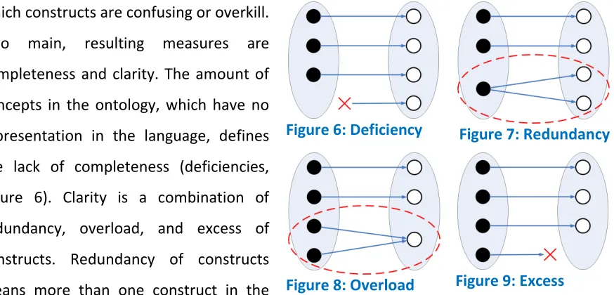
which constructs are confusing or overkill. Two main, resulting measures are completeness and clarity. The amount of concepts in the ontology, which have no representation in the language, defines the lack of completeness (deficiencies, Figure 6). Clarity is a combination of redundancy, overload, and excess of constructs. Redundancy of constructs means more than one construct in the
language represent one concept in the ontology (Figure 7). Overload of constructs indicates that one construct in the language represents more than one concept in the ontology (Figure 8). For example, the EPC function construct represents a property in general, a process, or a transformation. Constructs that do not represent any concept of the ontology cause excess of constructs (Figure 9). For this research, it is not only important to compare the languages to the ontology, but also to see to what extent the results of the comparison match.
4.1.2 BPEL and the BWW model
[image:40.595.86.523.71.281.2]Prior research was conducted to evaluate BPEL according to the BWW model already (Green, Rosemann, Indulska, & Manning, 2007). BPEL has the ability to represent approximately half (51.7%) of the concepts in the BWW model. While only half does not seem good, only ebXML and BPMN scored better in a comparative study (Rosemann, Recker, Indulska, & Green, 2006). The most eye-catching deficiencies are the lack of the th