Index Terms—Hierarchical description, devices, clamping,
clamping mechanisms, analysis, synthesis.
Abstract— The paper presents a method of analysing devices
for clamping pieces to machine-tools. This method is based on the hierarchical description of technical systems. The stages of technical system hierarchical description are, at the same time, creativity levels that creation themes may attain. Thus, a complete creative approach of a field implies, first of all, a systematic analysis followed by a creative analysis, which can be achieved on various creativity levels. The advantage of the hierarchical description is that the devices’ construction and functioning are analysed thoroughly. Therefore, the analysis reaches as far as the physical effects, principles and laws of device construction and functioning. For this reason, as a result of such an analysis, one can generate highly original creation and innovation themes.
I. INTRODUCTION
In order to achieve a scientific creative synthesis of the technical systems, it is necessary that first and foremost, they are thoroughly analysed [5], [6], [8]. This analysis can be a very important premise both when applying the logical-combinatorial methods and techniques of creation and when applying the psychological-intuitive ones [9]. The analysis, “dissection”, taking apart of the fundamental components of technical systems is an activity often performed involuntarily, which is the natural reaction of the creator in the technological field [12], [13], [14]. Generally, the following aspects are taken into account when analysing a technical system:
– establishing the functions of the technical system; – establishing the general structure of the technical system;
– tracing the component elements;
– establishing relations between elements, etc.
To achieve this analysis, one of the technical invariants was employed, the order (hierarchy) of describing the technical objects. The technical invariants (the technical categories) are the basic elements used by inventics/ invention science [1], [2], [15], [16]. Other technical invariants are: the
Manuscript received March 23, 2011, revised April 7, 2011. This work was supported by Romanian Ministry of Education and Youth and National Authority for Scientific Research (CNCSIS), in the framework of PN-II-ID-PCE-2008-2 research programme (the project Exploratory Research Regarding the Dynamic Behaviour Correction of Distributed Mass Structures Using Modal Energy Absorbers - CNCSIS 313).
N. Seghedin is with the Technical University “Gheorghe Asachi”, B-dul Prof. Dr. Doc. Dimitrie Mangeron 61-63, 700050, Iasi, Romania (phone: +40 0232-278680; fax: +40 0232-242109; e-mail:
technical object and technology, the systemics (systematics) of the problems encountered in solution search and selection, technical objects ecology, enlisting attributes, development criteria, quality indicators and the shortcomings (contradictions) of the technical objects, the technical object model and the technical laws [4], [10], [11].
The stages of the hierarchical description of technical systems represent, at the same time, creativity levels that the creation themes have reached. Thus, a complete creative approach of a field implies, first and foremost, a systematic analysis, followed by a creative synthesis which can be made on various creativity levels [1], [3], [4], [7].
II. THE HIERARCHICAL DESCRIPTION OF TECHNICAL SYSTEMS (OBJECTS)
The order (hierarchy) of describing the technical objects is, according to A.I. Polovinkin, a work instrument that can be used with the purpose of structuring creation problems. Therefore, creation themes can be classified depending on the steps taken in the hierarchical description of technical systems. This hierarchical description can be connected with the types of creative problems suggested by A.I. Polovinkin [2]:
– selecting or searching the most efficient physical principle of action for the given concrete tasks and conditions;
– searching and determining the rational technical solution for the pre-established physical principle, through the overall structure, the form of the functional elements, materials, element number, through their relative location, and through the direction of the energetic flux;
– determining the parameters’ optimal sizes for the final technical solution.
On the other hand, the hierarchical description can be a technique of achieving a minute, systematic and scientific analysis of the studied technical object. Hence, according to the same author, each technical object can be presented using a sequence of descriptions that are hierarchically subordinated, which can be characterised by two fundamental properties:
– each new description is more detailed and characterises more thoroughly the technical object than the preceding description;
– each new description comprises the preceding one. The stages of this description are presented in fig.1. Another hierarchical description is suggested by W.G. Rodenaker in the paper [9]. This hierarchical description is presented with the purpose of a more precise characterisation of the technical objects (notions). Thus, a declarative (didactic) description is proposed first:
Hierarchical Description of Technological
Devices
1.the visual description of the object;
2.the obtaining procedure (technological procedure); 3.usage, technical, economical, ergonomic performances.
The second type of hierarchical description suggested by Rodenaker consists of the following stages:
1.mentioning the technical characteristics of the object; 2.the active physical principle (the functioning physical principle);
[image:2.595.49.290.192.337.2]3.the intentional action (purpose, function).
Fig. 1. The stages of the hierarchical description of the technical objects
II. 1. Technical Project (T.P.)
The technical project is the first stage in describing (analysing) the technical objects. The technical project is the complete form of presenting the technical documentation of performing a technical system. For each functional element are mentioned: the constructive form, material, dimensions, technical conditions, dimensional errors concerning the form and relative position, rugosities etc. During this first stage of analysis, the detail constructive elements, which define the analysed product completely, are studied.
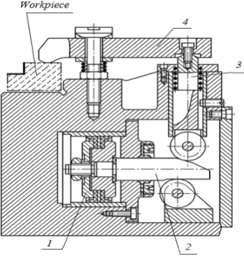
In fig. 2 there is a fragment from the technical project of a fixture during a cutting process.
Fig. 2. The technical project of a fixture
This device is performed pneumatically, aided by a pneumatic cylinder 1. The action force and stroke are
conducted to the working piece through a key 2, a plunger 3 and a lever 4. Technical details regarding the physical manner of achieving such an assembly can be noticed. Therefore, one can study the assembly elements, the sealing elements, the body of the device, joints etc. As a result creation themes referring to certain modifications, adjustments and improvements of the technical project alone can be formulated. These creation themes have a limited technical-economical impact, being characterised by a usually low creativity level.
II.2. Technical Solution (T.S.)
The technical solution could be in fact the presentation of the main, generic constructive variant of the analysed technical system. At this level of description constructive details are not mentioned, but only main constructive elements, which mostly define the way the analysed technical system functions.
The creation themes that can be structured as a consequence of the analysis at this level show a higher creative charge and can lead to significant constructive-functional changes.
In the case of the fixture in fig. 2, the technical solution is presented in fig. 3.
Q/Fa
Pa
Ca
S/Fs
[image:2.595.320.533.359.513.2]Cs
Fig. 3. The technical solution of the fixture in fig. 2 (pa air pressure, Q/Fa action force, sa action stroke, S/Fs clamping
force, cs clamping stroke)
In this case, the technical solution refers to the clamping mechanism and the action system contained by the analysed fixture structure. Thus, the technical solution consists of a double-effect pneumatic motor (cylinder), a key clamping mechanism, a roller plunger, and a lever.
II.3. Functioning Physical Principle (F.P.P.) The functioning physical principle of a technical object is made up of several physical effects combined serially, parallel and mixed. A physical-technical effect (PE) consists of three elements:
– entry action (A);
– the object that suffers the action (B);
– the effect of the action (physical effect) (C) and is formally represented by the relation:
PE = (A, B, C) (1) TP (TECHNICAL PROJECT)
TS(TECHNICAL SOLUTION) FP(FUNCTIONING PHYSICAL PRINCIPLE)
[image:2.595.80.255.550.740.2]If the functioning physical principle of a technical object is made up of a series of physical effects, then the exit effect of the first phenomenon is, at the same time, the entry action for the second one, meaning:
C1 = A2, (2) respectively,
FPP = (A1B1C1) (C1B2C2) (C2B3C3). (3)
If the fixtures are analysed, one must consider that in order to conduct the action force and stroke, a number of physics laws, effects and principles are used.
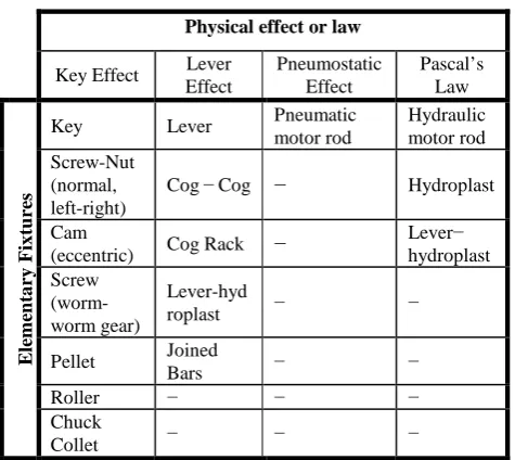
After analysing the elementary mechanisms that build up a clamping device, one could notice that they can be based, for instance, on the following effects and laws of physics (tab.1.) [17]:
[image:3.595.46.284.332.544.2]– key effect; – lever effect; – pneumostatic effect; – Pascal’s Law.
Table 1. The effects and laws of physics that describe the elementary fixtures
Physical effect or law
Key Effect Lever Effect Pneumostatic Effect Pascal’s Law E lem en ta ry F ix tu res
Key Lever Pneumatic
motor rod Hydraulic motor rod Screw-Nut (normal, left-right)
Cog − Cog − Hydroplast
Cam
(eccentric) Cog Rack −
Lever− hydroplast Screw (worm- worm gear) Lever-hyd
roplast − −
Pellet Joined
Bars − −
Roller − − −
Chuck
Collet − − −
The law of physics expresses the connection between the physical measures that characterise a phenomenon. The physical effect is a consequence, a result of a certain cause. Physical principles are truths that impose themselves due to the fact that they are not invalidated by the experiences of the field. Each of these effects and laws influences the way in which typical mechanisms conduct forces and motions. First of all, these effects and laws have a direct action on the manner in which fixtures transform motion. It has two
fundamental forms: rotation (R) and translation (T), every mechanism being characterised by one entry and one exit, which can specify their type of motion.
The result of the fixtures’ analysis was the possibility of stating a principle on whose basis one could explain the reason of ordering the typical fixtures in a certain way in the structure of combined fixtures. This principle was named the motion transmission compatibility principle: the necessary and sufficient condition that a sequence of two mechanisms is viable from a technical point of view is that the exit of the first mechanism be identical, as far as the motion form is concerned, with the entry of the second mechanism. This principle can be the selection grounds of those fixtures that are technically viable from the whole of possible mathematic combinations.
In the case of the analysed fixture, the action pneumatic system (pneumatic motor) functions based on the pneumostatic effect (the entry parameters being air pressure pa and debit q) and the fixtures are a materialisation of the key
effect (key mechanism) and the lever effect (lever mechanism). The plunger mechanism does not modify, in the absence of friction, neither the force, nor the motion (stroke), having the sole purpose of transmitting the mechanic object to a certain distance. Hence, the representation of the device in fig. 2 at this description level is that in fig. 4. One can see the physical effects and laws which characterise the functioning of each mechanism, as well as the motion form of the entry and exit of each mechanism (translation-T androtation-R).
II.4. Functional Structure (F.S.)
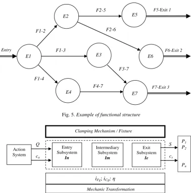
According to [1], the constructive-functional structure is an oriented graph, whose apexes are the elements and whose arms signify the functions of the elements (fig. 5).
In fig. 5 there is the functional structure of a system with 7 structural elements (E1, E2, E3, ..., E7), one entry and 3 exits. Also, the figure presents the connections between elements, which are, at the same time, the functions of these elements (F1-2, F1-3, F1-4, ..., F7-Exit 3). In the particular case of fixtures within the structure of clamping devices, the functional structure can be presented on three approach levels.
On a first approach level, as a result of analysing several fixtures and according to the papers [2], [3], the general structure of these mechanisms consists of three subsystems: entry (action) (In), intermediary (Im) and exit (Ie) (fig. 6).
The entry parameters are the action force and stroke (Q, ca), while the exit parameters are the clamping force and
stroke (S, cs). The entry parameters become exit parameters
through a mechanic transformation.
pa, q Q Q’ Q” S
[image:3.595.85.514.675.770.2]ca ca’ ca” cs
Fig. 5. Example of functional structure
Q S
ca cs
Fig. 6. The structure of clamping mechanisms/ fixtures The functions of static transfer, which characterise this
transformation, are the total rapport of force transmission (iFg), the rapport of stroke transmission (iCg) and the
mechanical efficiency (η).
The entry subsystem consists of those elements through
which energy is transmitted from the action system to the other subsystems of the fixture. There are cases in which clamping is made directly with the entry elements, when the other joints of the fixture are missing and the entry system is connected with one or more pieces P1, P2, …Pn.
The intermediary subsystem consists of elements that
transform (amplify or reduce) the action forces and strokes.
The exit subsystem consists of those elements that have
direct contact with the piece (pieces) – they are the elements that effectively ensure the clamping of the pieces in the device.
A second approach level establishes the structure of the entry, intermediary and exit subsystems. The results of the fixture analysis were:
─ the entry subsystem is materialised in one single element, because energy/power flux enters the mechanism through one single channel (channel, admission), after which there follows a dispersal of forces and strokes on more channels (channels, patterns), in the case of clamping more pieces;
─ the intermediary subsystem may be missing from the structure of the fixture or it can be materialised in one, two, three or four clamping elements. The extent to which intermediary subsystems may be materialised into a certain number of elements is presented in table 2;
Table 2. The number of elements that materialise the intermediary subsystem
The number of elements that may materialise the intermediary subsystem
0 1 2 3 4
The ponderosity from the total of studied intermediary subsystems
34% 34% 22% 9% 1%
─ the exit subsystem may be missing, case in which it is confused with the entry subsystem; this subsystem is materialised, almost every time, by one single element;
─ the structure of multiple fixtures, unlike that of simple fixtures, is an arborescent (symmetrical or unsymmetrical) structure.
F3-7 E1
Entry
E2
E3
E5
E4 E7
E6
F5-Exit 1
F6-Exit 2
F7-Exit 3 F1-2
F1-3
F1-4
F2-5
F2-6
F4-7
Clamping Mechanism / Fixture
Entry Subsystem
In
Intermediary Subsystem
Im
Exit Subsystem
Ie
i
Fg;
i
Cg;
η
Mechanic Transformation Action
System
P1 P2
According to what was mentioned above, the functional structure of fixtures can be encountered in many variants. Thus, one can see that the functional structures underlying the achievement of fixtures can be encountered in a very large number for the following reasons:
– the elements of each subsystem (entry, intermediary, exit) may have more exits;
– the number of generic elements in the intermediary subsystem can be from 0 to 3;
– the functional structures may be linear or arborescent, symmetrical or asymmetrical.
The third analysis level of fixtures, as far as the functional structure is concerned, refers to the types of elementary mechanisms (typical, specific) that materialise the entry, intermediary and exit subsystems. After the analysis of several fixtures, the conclusion was that their structure may contain the typical (specific) clamping elements (mechanisms) (Entry Elements: Screw-Nut (normal, left-right); Motor Rod; Cam (eccentric); Lever. Intermediary Elements: Plunger (rod); Lever; Hydroplast Lever; Hydroplast; Roller; Pellet; Joined Bars; Key (cone); Cog Rack; Screw; Cam (eccentric); Screw (worm-worm gear); Cog – Cog. Exit elements: Lever; Plunger; Jaw; Prism; Key Lever; Key; Spring; Roller; Chuck Collet).
One can notice that, besides the elementary fixtures usually encountered in the field (screw, key, lever etc.), there is a series of hybrid elements emphasised (hydroplast lever, key lever etc.). These hybrid elements are a result of the fusion of two elementary mechanisms (usually), comprising, therefore, the advantages and disadvantages of these elementary mechanisms. The table also emphasises the frequency with which these mechanisms occur in the studied fixture structures.
In the case of the device in fig. 2, the functional structure is that in fig. 7.
II.5. Technical Function (T.F.)
The structure of the technical function comprises the task (T) satisfied by the technical object and the physical operation (P) by the means of which this task is completed. The formalised descriptor consists of two terms [1]:
T.F. = (T, P). (4) The physical operation (P) can be formally represented by three components:
– the entry flux of the substance - F1; – the exit flux of the substance - F2;
– Koller operation (K) of changing F1 into F2. Therefore,
F = (F1, K, F2 ). (5)
This descriptor answers the questions “what” (F1), “how” (K) and “into what” (F2) is transformed through the described technical object (TO).
Otherwise said, it is at this description level that the way in which entry energy is transformed in exit energy is established. In the case of clamping devices it is established how action energy is transformed into piece clamping energy.
When clamping pieces in processing operations, several transformational physical operations can be used.
According to the tasks of this level of the hierarchical description, task T is to orient-position-clamp the piece. If only clamping the piece in the device is implied, the Koller transformational operation (transformational physical operation) through which this task is completed can be:
– Mechanical transformation of the mechanic work in action into clamping mechanic work through the clamping mechanisms;
– Pneumostatic transformation of the energy of the compressed air into mechanic work;
– Hydrostatic transformation of the energy of the liquid under pressure into mechanic work;
– Electrostatic transformation. Due to Coulomb’s Law, the electrostatic charge can generate the clamping of more pieces that are charged. Restrictions, in this case, are connected to the magnitude of the electrostatic attraction forces, labour protection etc.;
– Magnetic transformation. Some constant magnets can achieve magnetic attraction which can generate clamping forces. Following this principle, magnetic masses were carried out and used in the processing operations. Restrictions, in this case, are connected to the nature of the material the pieces are made of (alloys) and cutting conditions;
– Electromagnetic transformation. The pieces are clamped due to electromagnet forces generated by electromagnets placed in electromagnetic chucks. Restrictions refer to the nature of the material the pieces to be clamped are made of (ferromagnetic alloys), the length of the cutting process etc.;
– Vacuumatic transformation. The clamping force is due to the difference between the atmospheric pressure on the pieces and the formation of a cavity under the semi-product aided by special equipment to produce the void. Restrictions are connected to pieces with holes and the magnitude of the cutting forces;
– Adherence transformation. The pieces can effectively be glued up with various adhesives with the purpose of procession, assembly or verification [14];
– Cohesion transformation. The pieces can be immersed in a material that changes its aggregation state at various temperatures. The pieces can be clamped with certain slightly fusible alloys or with frozen water. Restrictions are linked to work temperature, forces’ magnitude;
p
a,q
Q Q’ Q” S
s
as
a’ s
a” c
sFig. 7. The functional structure of the device in fig. 2 Pneumatic
– Gravitational transformation. The pieces can be clamped simultaneously due to a suspended plate. Also, heavy pieces can be simultaneously clamped when, under their own weight and under the action of the cutting, assembly, and measurement forces, they can remain stable. Restrictions are connected to the weight of the pieces and the magnitude of exterior forces;
– Thermal transformation. The pieces can be clamped with elements that dilate under the action of temperature growth. Restrictions: the influence of temperature on the clamped pieces and the long period of clamping [14];
– Archimedes force transformation. The pieces can be clamped (at least theoretically) [14] due to Archimedes’ force, which occurs when they are immersed in a liquid.
These physical operations of transformation represent an important resource of creation themes in the field of clamping devices.
In the case of fixtures, the action force (Q) and action stroke (ca) are turned into clamping force (S) and clamping
stroke (cs).
The transformational Koller operation is the mechanic transformation. Thus, the technical function will comprise the tasks (functions, attributes, including special conditions and restrictions), to which the following elements are added:
– Q = action force; – sa = action stroke;
– C = clamping forces; – sc = clamping strokes;
–
i
Fg= the total rapport of force transformation; –i
Cg= the total rapport of stroke transformation; – η = mechanical transformation efficiency (η =Cg
Fg
i
i
×
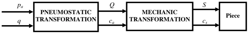
).Besides, one should also take into account the pneumostatic transformation of the compressed air energy into mechanic work that is necessary to action the clamping mechanism. Thus, the pressure p and debit q of the compressed air will become the action force Q and the speed s of the primer rod (due to the functional particularities of the fixtures, the main exit parameters will be the force Q and the stroke sa).
The conclusion could be that the technical function of a fixture is to complete the tasks T (orientation-positioning-clamping) through certain physical operations of energy transformation.
In the case of the fixture in fig. 2, its technical function, expressed synthetically through the transformational Koller operations, is presented in fig. 8.
II.6. Task (function, attribute) (T.)
The task is a brief description, in natural language, of the technical purpose, answering the question “What is the final purpose and what special conditions and restrictions must strictly be obeyed?”
In the case of the clamping devices at this analysis (description) level, the following tasks must be established:
a. the number of pieces to be clamped; b. pieces arrangement;
c. the number of forces applied on a piece;
d. the direction and orientation of the applied forces; e. the magnitude of the clamping forces;
f. . the magnitude of the clamping strokes etc.
Also, the special conditions and restrictions are connected to the following aspects:
– orientation-positioning precision; – clamping precision;
– the uniformity degree of clamping the pieces; – time norm;
– the possibility of clamping pieces with various configurations;
– contact deformities; – rigidity;
– attrition; – durability;
– resistance to fatigue break; – self-stopping securement degree; – force transmission stability; – access to work area; – universality degree; – complexity; – volume and mass.
These aspects behave, in fact, as restriction as well. From this list, in an actual case, only those elements relevant to the respective situation should be chosen.
Some of the most important tasks that fixtures have to complete are the optimal orientation-positioning schema and the optimal clamping schema. The optimal orientation-positioning schema is a graphic representation that gives information about the areas used for orientation-positioning, the freedom degrees undertaken on these areas, the used bearings etc.
The optimal clamping schema gives information about the clamping forces’ number, size, direction, orientation, application point and succession that are applied to the piece etc.According to [2], the task (T) of the technical system should contain the name of the action (A), the actioned object (O) and the special conditions and restrictions (R); therefore, the formalised descriptor comprises the three terms:
p
aQ S
[image:6.595.88.484.672.729.2]q c
ac
sFig. 8. Transformational Koller operations in the case of the fixture in fig.2 MECHANIC
TRANSFORMATION Piece
C = (A, O, R) (6)
In the case of the clamping devices, the three terms are:
● The action developed by the device is clamping the
piece, which means its orientation-positioning and clamping;
● The actioned object represented by the clamped piece (pieces);
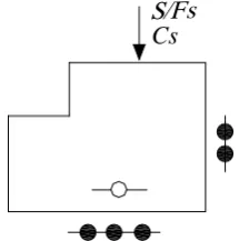
● The restrictions and special conditions listed above. In the case of the device in fig. 3.2, the task can be represented as in fig. 9.
S/Fs
[image:7.595.113.221.173.282.2]Cs
Fig. 9. The task imposed to the fixture in fig. 2 The successive stages of hierarchical description of the device in fig. 2 can be represented synthetically after the model in the paper [4], as in Annex 1.
III. Conclusions
The hierarchical description of technical systems is a method of maximum generality, which can be used in order to achieve a systematic analysis. The paper presents the application of the method on fixtures. After going through all the stages of the devices’ hierarchical description, the variable parameters that characterise each stage are established. This way, the general context is created, which allows, at least theoretically, the hierarchical description of any device. The analysis achieved as a result of the hierarchical description permits the structuring, in the field of devices, of new creation themes with various levels of novelty.
REFERENCES
[1] Aghezzaf E., Sitompul C., Van den Broecke F., . Computers & Industrial Engineering, vol. 60, Issue 2,pages 361-372,2011.
[2] Belousov V., Inventica. Ed. Gh. Asachi, Iaşi, 1992.
[3] Fahmy S., Balakrishnan S., El Mekkawy T
Manufacturing, vol. 27, issue 3, pages 591-603, 2011.
[4] Gherghel N. „Considerarea dispozitivului de prindere ca sistem în
creaţia ştiinţifică şitehnică”. Lucrările celui de-al III-lea Simpozion
naţional de inventică, Iaşi, 1988.
[5] Gherghel, N. „Viziunea sistemică asupra dispozitivelor de prindere-sursă importantă de idei creative”, in Revista de inventică, Vol. I, an 1, nr. 2, septembrie, 1990.
[6] Gherghel N., Seghedin N., Hanganu A.C., „The hierarchical description of the technological devices’ hydraulic action”, in Bul.
Inst. Polit. Iaşi (publicat de Universitatea Tehnică “Gh. Asachi”
Iaşi), tomul LIII (LVII), fasc. 5, secţia Construcţii deMaşini, 2007, pp. 245-254.
[7] Karshenas H., Nikanjam A., Helmi B.H., et al Conference on Intelligent Computing and Intelligent Systems, nov. 20-22, 2009, Shanghai. 2009 IEEE International Conference On
Intelligent Computing And Intelligent Systems (ICIS 2009), vol 1-4,
pages 848-852, 2009.
[8] Plahteanu B., Pleşu Gh., Călătoru V., Hanganu Şt., Concepţia şi
proiectarea creativă a maşinilor-unelte. Ed. Performantica, Iaşi, 2001.
[9] Rodenacker, W. G. Maschinenbau Heute und Morgen. Neue Lernziele und Lerninhalte. Expert Verlag, Berlin, 1983.
[10] Seghedin N., „Ierarhia descrierii mecanismelor de strângere multiplă” in Revista de inventică, 22-23, vol.IV, an X, 1999, p. 22-28. [11] Seghedin N., „Analiza structurală a mecanismelor de strângere
multiplă”in Construcţia de maşini,(52), nr.11, 2000, pp. 25-28. [12] Seghedin N., “Methodology for Clamping Mechanisms Analisys” in
Annals of DAAAM for 2001 and Proceeding of 12th International DAAAM Symposium "Intelligent Manufacturing & Automation: Focus on Precision Engineering", Editor: B. Katalinic, ISBN 3-901509-19-4, 24-27th October 2001, Jena, Germany, Published by DAAAM International, Vienna, 2001, pp. 433-434.
[13] Seghedin N., Analiza şi sinteza structurală creativă a mecanismelor
de strângere multiplă. Ed. Tehnopress, Iaşi, 2002, ISBN 973-8048-95-8.
[14] Seghedin N., „Usage of the Hierarchical Description of the Technical Systems for the Structuring the Creative Problems in the Field of the Clamping Devices”in Bul. Inst. Politehn. Iaşi (publicat de Universitatea Tehnică “Gh. Asachi” Iaşi), Tomul L (LIV), Fasc.
Va, Secţia Constr. de maş., 2004, pp. 133-136. [15] Seghedin N., Dispozitive. Ed. PIM, Iaşi, 2008.
[16] Seghedin N., Aplicaţii în creaţia tehnică. Ed. Performantica, Iaşi, 2008.
[17] * * * Vorrichtungen. Rationelle Planung und Konstruktion. VDI
Annex 1. The hierarchical description stages of the device infig. 2
Technical Project (T.P.)
Technical Solution (T.S.)
Q/Fa
Pa
Ca S/Fs
Cs
Functioning Physical Principle (F.P.P.)
Functional Structure (F.S.)
Technical Function (T.F.)
Task (function, attribute) (T.) S/Fs