Abstract— Electrochemical machining (ECM) is an important manufacture technology in machining difficult-to-cut materials and to shape complicated contours and profiles with high material removal rate without tool wear and without inducing residual stress. This paper presents the physical and mathematical models on the basis of which of the Simulation Process Module in the Computer-Aided Engineering System (CAE-ECM) for ECM has been developed. The results of computer simulation of electrochemical sinking and examples of CAE-ECM System application are discussed.
Index Terms—electrochemical machining, ECM, computer simulation, mathematical modeling
I. INTRODUCTION
Electrochemical machining (ECM) is an important manufacture technology in machining difficult-to-cut materials and to shape complicated contours and profiles with high material removal rate without tool wear and
[image:1.595.53.290.390.560.2]without inducing residual stress.
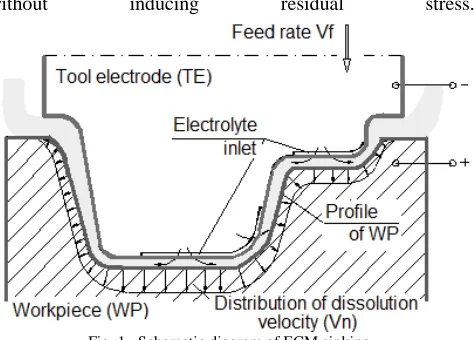
Fig. 1. Schematic diagram of ECM sinking.
As shown in Fig. 1 machining based on controlled anodic electrochemical dissolution process in which the workpiece is the anode and the tool is the cathode of an electrolytic cell. In the ECM process, a low voltage (8-30V) is normally applied between electrodes with a small gap size (usually 0.2 to 0.8 mm) producing a high current density of the order of (10 to 100 A/cm2), and a metal removing rate ranging from an order 0.1 mm/min, to 10 mm/min. Electrolyte (typically NaCl or NaNO3 aqueous solutions) is supplied to flow through the gap with a velocity of 10 to 50 m/s to maintain the electrochemical dissolution with high rate and to flush away the reactions products (usually gases and hydroxides)
Manuscript received July 19, 2011; revised August 7, 2011. This work was supported in part by the Polish Ministry of Science and Higher Education.
J. Kozak is with the Institute of Aviation, Al.Krakowska 110/114, 02-256 Warsaw Poland (fax: +48 22 846 44 32; e-mail: [email protected]).
and heat generated caused by the passage of current and electrochemical reactions.
As electrochemical dissolution proceeds, the tool electrode-cathode can be fed mechanically towards the workpiece - anode in order to maintain the machining action. Under these conditions, the inter-electrode gap width gradually tends to a steady-state value, and a shape, complementary to that of the cathode-tool, is reproduced approximately on the anode-workpiece. Being a non-mechanical metal removal process, ECM is capable of machining any electrically-conductive material with high stock removal rates regardless of their mechanical properties, such as hardness, elasticity and brittleness. It has been applied in diverse industries such as aerospace, automotive and electronics to manufacture airfoils and turbine blades, die and mold, artillery projectiles, surgical implants and prostheses, etc. [1]-[5].
The main objective of ECM is to achieve the required shape of workpiece within a given tolerance on the shape and dimensions. The tasks relating to this purpose can be reduced directly (or indirectly) to a problem of searching for a boundary of the area within which the machining, i.e. to a value boundary problems (moving boundary problem, free boundary problem or inverse boundary problem).
Depending on which the electrode surface is to be determined all tasks can be divided into two groups [1]–[9]: 1 - tasks in which for a known shape of the tool electrode and known condition of machining, the evolution of a shape of workpiece surface has to be determined,
2 - tasks in which the tool electrode shape is searched for, which ensures obtaining the required shape of the workpiece.
The first category of the problems is encountered in the analysis of ECM accuracy. The tasks from the second category mainly deal with the tool electrode design and most frequently are encountered in practice.
Industrial practices in ECM have revealed some problems impeding its further development and wider acceptance by industrial users. Among them, prediction and control of the local gap width distribution (and hence, the control of dimensional accuracy), along with the design of tool electrodes for complex workpiece shapes and optimization of process, are the major problems encountered by ECM users.
The optimization and tool - electrode design is carried out using ECM process models. Software for the computer-aided ECM (CAE-ECM) has been developed in Warsaw University of Technology covers basic manufacturing problems ECM [3], [4], [8] and [9].
The paper presents the physical and mathematical models, basis of which a process simulation module has been
Computer Simulation of Electrochemical
Machining
developed the ECM sinking. The example of results of simulation by CAE-ECM System are discussed.
II. MATHEMATICAL MODELING OF ECM SINKING PROCESS The main task of the electrochemical shaping, regardless of variant, is to calculate distribution of the material removed thickness on the anode-workpiece surface after a time step used in numerical calculations, which is determined by current density distribution in the gap, in particular in a medium of varying electrical conductivity, with complex processes occurring on the surfaces of the electrodes and with shape change of machined surface during course of machining. Since properties of electrolyte depend on temperature and gas phase concentration (mainly on concentration of generated during machining hydrogen), which distributions depend on velocity and pressure fields as well as on current density, ECM processes have to be described by set of mass, heat and electric charge transfer equations.
The problem of determining the changes shape of machining surface and physical conditions in the inter-electrode gap for transit and steady state of the ECM with using contoured cylindrical tool-electrode is consider in this paper (Fig. 2).
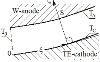
[image:2.595.50.287.453.590.2]The electrode flow is from left to right in a thin gap of local size S and of length L. The down surface is the tool-electrode which moves upward with feed rate Vf. At a point opposite the tool, the workpiece surface is moving upward with local velocity Vn. This distribution of the velocity of dissolution and the change of physical conditions along the flow path evoke non-uniform distribution of the gap size S and a shape error of the workpiece-anode.
Fig. 2. Schematic diagram for mathematical model of ECM sinking.
The mathematical model of ECM process, referring to the formulated problems consists of sequence of mutual conjugated partial models which describe in the gap: - distribution of the local gap size, S,
- distribution of the flow parameters such as the static pressure p(x) and the velocity, w,
- distribution of the temperature, T,
- distribution of the void fraction, ββββ or the thickness layer h with two phase flow (electrolyte and gas),
- distribution of the electrical conductivity, κκκκ,
The physical model with the following assumptions serves as the basis for mathematical modeling [8]:
1. The three regions can be identified in the gap: 1- the region with pure electrolyte, 2- the bubble region near cathode with thickness h <<<< S and which consist of
mixture of electrolyte and gas (hydrogen), where the void fraction of hydrogen in the bubble region layer is constant and equal ββββ*, 3 - the region of two phase flow
witch change of ββββ,
2. The current density i is depends on medium conductivity in the gap and on the voltage U according to Ohm’s law, which is extrapolated to the whole gap size. The electrochemical reaction will be accounted for by introducing the total overpotential
E = Ea - Ec, where Ea and Ec are the overpotential
potential of anode and cathode, respectively,
3. The surface tension effect on the gas bubbles is neglected, and so is the bubble formation time,
4. Since analytical models of Kv = Kv(i) and E = E(i) are not
available, experimental results are used with theoretical model,
5. The effect of bubble layers on pressure and the flow velocity of the electrolyte is accounted by consideration of a homogeneous two-phase model flow, where the electrolyte in the gap is treated as a uniformly-mixed pseudo-continuous medium of gas and liquid with local average void fraction:
β β
= ∗h S0<h<S (1) 6. The electrical conductive of the two-phase medium can
be determined by the Bruggeman equation:
[
]
(
)
3/21
1 α θ β
κ
κ = o + T − (2) where: θ = T - To, To = inlet electrolyte temperature, αT = the temperature coefficient of the electrolyte conductivity at To, and κo = electrolyte conductivity at To and β = 0.
To formulate the mathematical model, a general case describing change in shape of the surface of the workpiece can be examined using coordinate system attached to the workpiece, which is immovable during machining (Fig. 3).
[image:2.595.342.507.557.660.2]To simplify the calculations let us introduce a curvilinear coordinate system (ξ ,ζ ), connected with the tool-electrode in which a coordinate ξ lies on the given electrode and is measured from the inlet of the electrolyte and let axis ζ overlap its normal nC (Fig. 2 and Fig. 3).
Fig.3. Scheme of the curvilinear coordinate system
The surface of the workpiece at a given moment in time can be described by: z = Z(x, y,). According to electrochemical shaping theory, the evolution of the shape of the workpiece F(x, y, t), can be described as follows [3]-[5]:
( )
1 2 2 + + =
y Z x
Z i
i K t Z
A A v
∂
∂
∂
∂
∂
where: KV is the coefficient electrochemical machinability, which is defined as the volume of material dissolved per unit electrical charge.
At the beginning of machining: t = 0, z = Z0(x, y), where: Z0(x, y) describes an initial shape of the workpiece surface.
To find the current density iA on the surface of the workpiece, approximation using linearization of electric potential distribution along the segments of distance S between a given point of anode and given point on the TE has been applied [3], [4]. The current density can be obtained by Ohm’s law with respect of change of conductivity across the gap:
S
E
U
i
o TG−
=
κ
φ
(4) where:∫
− − + = S o T TG T d S 1 2 / 3 ] ) 1 )( 1 ( 1 [β
α
ζ
φ
(5)The equation of mass conservation for the hydrogen generation in the case of cylindrical electrodes and curvilinear coordinates can be obtained from mass balance as:
∫
=∫
∗oh H H o
g w d K id
ξ ξ
η ζ ζ β
ρ ( ) (6) where:
RT p
g =
ρ
- specific gas density of hydrogen, R = gas constant for 1 kg of hydrogen, ηH = current efficiency of the hydrogen generation, KH = electrochemical equivalent of hydrogen,w( )
ξ
- average velocity in the given cross section of the gap.The heat transfer in the gap with respect to Joule’s heat is described by: κ ρ ∂ζ ∂ ∂ζ∂ ∂ξ ∂ ζ ξ ⋅ ⋅ + ⋅ + = ⋅ p T C i T a a T w 2 ) ( ) ,
( (7)
where: a - thermal diffusivity, aT - turbulent thermal diffusivity by turbulence pulses (for laminar flow aT = 0), ρ - specific medium density (in the region 1 ρ = ρe, and in the region 2 and 3 ρ=ρe(1−β) where ρe - density of electrolyte and Cp – heat capacity of electrolyte.
The boundary conditions are as follows: T(ξ=0) = To, T(ξ, 0) = TA, T(ξ, S) = TC, where: TA and TC are temperatures of the anode and cathode, respectively.
To complete of the systems of Eqs. (2) - (7), the formulation the pressure and the flow rate must be included. The continuity equation can be expressed by:
ζ β wd S
wo =
∫
oS (1− ) (8) where:w S
o,
o - average velocity and gap size in inlet, respectively.The momentum balance equation for the moving control is:
[
]
c a e d dp S d S w dw τ τ
ξ ξ
β
ρ ⋅ − ⋅ ⋅ =− ⋅ − −
⋅ (1 ) (9)
where: τa and τc are the shear stresses on the surfaces of anode and cathode, which are assumed to be equal (τa = τc). In general, the shear stress is expressed as follows:
τ λ ρ= w2
8
(10)
where λ=C Re/ m ,
ν
wS
2
Re= is Reynolds number (for laminar flow: C=96 and m=1; for turbulent: C=0.316 and
m=0.25).
The boundary conditions for Eqn. (9) is described by:
2 ) 0 ( 2 1 o in w p
p
ξ
= = −ς
ρ
;2 ) ( 2 2 w p L
p
ξ
= = out+ς
ρ
, where: 21,ς
ς is the hydraulic loss pressure in the inlet and the outlet, respectively.
The system of equations (2) - (9) has been solved numerically using the Finite Difference Method and iterative procedure.
In the first iteration one-dimensional approximation has been used for distribution of temperature and for determination of change of thickness the bubble layer h(1), next this distribution of h(1) is used in the second iteration and in the first approximation of two-dimensional (2-D) calculation of temperature distribution. Calculation of a given iterative cycle are finished, when the criteria of accuracy of calculation is satisfied and the simulation ECM process culminates in printout and plots of: the gap distribution and distributions of p, w, T, β.
After analysis of results of computer simulation of ECM at different operating parameters, the critical conditions can be determined from the point of view of the process limitations such as: boiling, choking flow and cavitation.
III. COMPUTER SIMULATION SYSTEM FOR ELECTROCHEMICAL SHAPING
A. Structure of the CAE-ECM System
The developed CAE-ECM System is based on the conventional concepts of the expert system, in which the user interface, knowledge base, working data base and inference engine. Generally expert systems are classified as being of either of two types: the analytical type or the synthetic type. A diagnosis expert system is a typical example of analytical type, while a design system is an example of the synthetic type.
First type can be used for:
• selection of electrochemical methods of manufacturing leading to obtain required results (for example: deburring, sinking, EC-drilling etc.),
• simulation of different ECM processes for analyzing machining conditions and the results of machining,
• recognition and diagnosis the causes of the trouble in EC - manufacturing and suggest some remedies for them.
Second type can be used for:
• planning and optimization of conditions of selected method of EC-manufacturing,
• tool electrode design for ECM,
The presented CAE-ECM System can also serve as training and learning tool. Using the System the inexperienced engineers in EC-manufacturing or operators may get to know about the applicability of electrochemical technology for certain job, the selection of methods, the preparation of tooling and planning of operations, the analysis of some defects during machining and trouble-shooting etc.
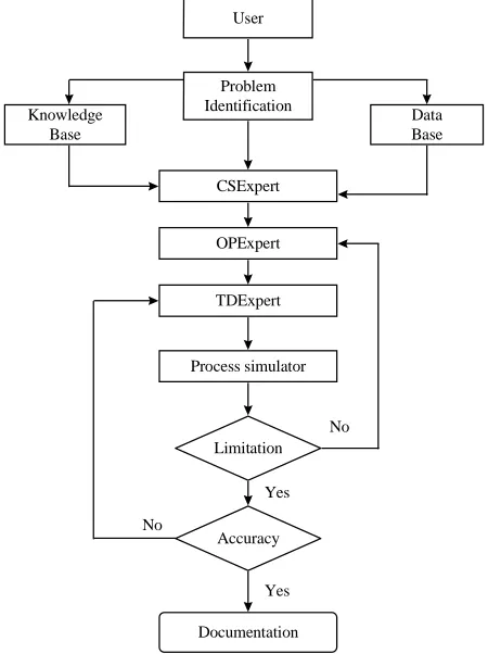
The general structure of the CAE-ECM software is shown in Fig.4.
The knowledge base is comprised of two forms of information:
(1) files which hold principal mathematical relations and characteristics of different methods of EC-manufacturing, (2) other data held as facts or in rule-based forms.
The working data base also holds two forms information. The first type of information relates to data about the electrolytes, materials of workpiece process, limitations of machine tool etc.
Data Base Knowledge
Base
Problem Identification
CSExpert
OPExpert
TDExpert
Process simulator
Limitation
Accuracy
Documentation No
Yes
No
User
[image:4.595.320.534.90.252.2]Yes
Fig. 4. Architecture of the CAE-ECM software.
This type data is different for each methods of EC-manufacturing (for example: at ECM - shaping and finishing it is relation between the electrochemical machinability and current density; at electropolishing it is volt-ampere curves, etc.).
The second is the information which is inferred and computed by the system. For example, computed function for EC-machinibility after filling experimental data for „new” material of workpiece, which must be included to CAE-ECM System. The machining condition and parameters for the simulation of process and tool design is provided by the conditions selection module CSExpert (Fig. 4).
The operating parameters are selected by OPExpert module, uses transferred information from Process
Simulator module and tool design module TDExpert.
[image:4.595.56.281.275.576.2]The software of CAE-ECM System is based on multithread structure, which enables parallel simulation of many processes for different input data.
[image:4.595.314.541.276.429.2]Fig. 5. Window for physical parameters of the process.
Fig. 6. Window with database of function KV.
Fig. 7. Data base of machine tool used in Center for Nontraditional Manufacturing and Research at University of Nebraska - Lincoln.
[image:4.595.317.536.449.616.2]shape of electrodes is given by points – interpolation of splain functions is applied. The window for given electrodes contains options of saving designed shape of electrode or getting the shape from database.
Beside input data connected with physical parameters of modeling, program gives the possibility of establishing (also during simulation process) of the speed and preciseness of presented graphics connected with time step. In case of omitting such parameters, program uses default data. Buttons responsible for graphics presentation (start, pause, next step, previous step, that enable more precise analysis of shape evolution), are situated on the tool strip in the main window. After completed modeling, user can get the display of output data from hand menu of the process window.
Program simulating electrochemical sinking process is integrated with database, which gives possibility to save full set of physical parameters, shapes of electrodes and settings of presentation.
Results of simulation such as the distributions of gap size, current density, static pressure, void fraction, average temperature and temperature across and along the gap can be saved and displayed. Several windows connected with input and output data are illustrated Fig. 5, 6 and 7.
B.
An example of results of simulation of ECM
sinking
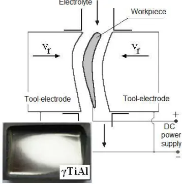
[image:5.595.313.540.49.213.2]To illustrate application of CAE-ECM System simulation of ECM sinking operation for shaping, of airfoils are considered (Fig. 8).
Fig. 8. Electrochemical sinking operation at manufacturing airfoil.
For given anode (workpiece) profile, the tool electrode shape was designed using the CAE-ECM system
Examples of simulation of ECM shaping are shown in Fig. 9, where subsequent graphs illustrate anode-workpiece shape evolution in time.
Fig.9. Screen print-out containing the evolution of the shape of the workpiece during machining.
[image:5.595.317.539.286.422.2]The gap size distribution with neglecting changes of properties electrolyte i.e. under “ideal” conditions of ECM, is shown in Fig. 8.
Fig. 10. Distribution the gap size in steady state ECM with neglecting influence of the heat and hydrogen generation (i.e. from the model of ideal
ECM process).
[image:5.595.79.258.400.581.2]In practice, ECM conditions are far to the ideal process of electrochemical shaping. In consequence, the material removal rate is distributed over the anode-workpiece surface in a different way in compare with the distribution in “ideal” process, and the machined part takes on a profile from that found from mathematical modeling and theoretical design. Calculation that is more exact needed simulation of all shaping process with regarding heat and mass transfer, as well as anodic dissolution characteristics.
Fig. 11. Plot of distribution of the gap size in steady state of ECM with regarding changes of properties of the electrolyte due to heating and gas
generation.
[image:5.595.313.542.577.715.2]The minimum practical tool gap size, which may be employed, however is constrained by the onset of unwanted electrical discharges. These short electrical circuits reduce the surface quality of the workpiece, and led to electro-erosive wear of the tool-electrode, and usually machining cannot progress because of them. Investigations of electrical discharges in an electrolyte reveal that the probability of electrical breakdown the gap is a function of the evolution of gaseous-vapor layers and passivation of the work surface. Intense heating, hydrogen generation sometimes choking phenomena and cavitation within the gap can lead to evaporation and subsequent gas evolution, and it is this gas which is believed to cause the onset of electrical discharge.
The issue of heating of electrolyte is primary importance for the determination of limit condition of ECM process. The distribution of mean temperature in the inter-electrode gap along the flow was determined using one-dimensional mathematical model of ECM process [1]. Further specification of temperature distribution was revealed in [3], [7]-[9]. Due to the heat exchange through electrodes as well as distribution of electrolyte velocity, the temperature changes along the flow path as well across the gap size.
Fig.12. The steady distribution temperature in the gap with size S = 0.1 [mm], (U=9 [V], E=3 [V], flow rate 6 [m/s], electrolyte: 12%
NaNO3).
The electrolyte temperature distributions across the gap width, at the different distances from the inlet electrolyte in ECM process with inter-electrode gap size S=0.1 [mm] is shown in Fig. 12.
The two maxims that can be observed in (Fig. 12) in proximity of electrodes are very important in ECM input parameters selection. The input parameters should always be chosen such that the maximum temperature of electrolyte never reaches its boiling point. One - dimensional model, in which only average values of (T, and β) across the gap can be calculated, may not be accurate enough to properly estimate the maximum temperature.
For example, in the Fig. 12, the maximum average increment of temperature is ∆Tav =32 [oK], in this time, the maximum temperature, as shown in Fig. 12 is ∆Tmax =46.47 [oK]. Use of input parameters from simulation that underestimated electrolyte temperature for actual machining may lead to short-circuit between electrodes and, what follows, to damage of tool and workpiece.
IV. CONCLUSION
The presented CAE-ECM system can be useful for process planning for different variants of ECM. It can be used for process analysis, tool design and parameters selection. Presented software has significant potential to be used in industry applications.
REFERENCES
[1] J. A. McGeough: Principles of Electrochemical Machining. Chapman & Hall, London, 1974.
[2] K. P. Rajurkar, J. A. McGeough, J. Kozak, A. De Silva: New Developments in Electro-Chemical Machining, Annals of the CIRP Vol.48/2, pp. 567-579, 1999.
[3] J. Kozak: Surface Shaping by Electrochemical Machining. Transaction of Warsaw University of Technology (WUT), Warszawa, (in Polish), 1976.
[4] A. D. Davydov, J. Kozak: High Rate Electrochemical Shaping. Ed.Nauka, Moscow, (in Russian). 1990.
[5] A.D. Davydov, V.,M. Volgin: Electrochemical Machining. in
Encyclopedia of Electrochemistry, vol.5. Chapter 12.
Electrochemical Engineering, A. J. Bard, Ed.New York,Willey-VCH, 2007.
[6] C. S. Chang, L. W. Hornung: Two-dimensional two-phase numerical model for tool design in electrochemical machining.Applied Electrochemistry, 31, 2001, pp.145–154.
[7] V. V. Klokov, E. E. Filatov, A. G. Firsov, A. Tikhonov: The complex computer simulation of the ECM blades shaping. The Proceedings of
the 15th Int. Con. on Computer-Aided ProductionEngineering
CAPE’99, 1999, Durham, UK, pp. 451-456.
[8] J. Kozak: Mathematical Models for Computer Simulation of Electrochemical Machining Processes. Journal of Materials
Processing Technology, Volume 76, N.1-3, 1998, pp.170-175.