Simulink Modelling of PV System in Micro-grid
using Robust Control Mechanism
Chandan Kumar1, Dr. Samina Elyas Mubeen2
1
M-tech scholar (Power System),2Head of Department (HOD), Department of Electrical & Electronics Engg. REC Bhopal (INDIA)
Abstract: Micro-grid is the major part of future electrical power structures, referred to as "smart grids". In this context, synchronization of a micro-grid with software or other micro-grids might be a critical and common challenge throughout the electricity system operation. Based on the sturdy manipulate principles, a new approach for synchronizing micro-grid. The problem of manipulate or control of parallel-related photovoltaic (PV) based totally distributed era (DG) gadgets in an AC distribution system is studied in this work. Firstly, a new strong back-again-stepping sliding mode based maximum strength or power point monitoring (MPPT) strategy is designed for each PV machine. Then, a brand new manipulate scheme is provided for electricity management of parallel-linked inverters of PV systems.
Keywords: PV, DG, MPPT, Parallel architecture, Micro-Grid, Power System.
I. INTRODUCTION
Renewable energy is harvested from nature, it's clean and free. However, it's wide accepted that renewable energy isn't a nostrum that comes while not challenges. As associate interface between the distributed generation (DG) plants and also the grid, the grid-connected inverters are essential to convert every kind of generated power into a top quality AC power and inject it into the grid dependably.
The inverters put in in dg plants are typically voltage supply inverters with associate output filter [1-2].
Nowadays, distributed generations (DGs) are incrementally penetrating into trendy electrical distribution systems as a result of challenges such as increasing demand for energy, environmental issues, and increasing reliable-ness in power systems [1-2]. during this context, a micro-grid is specifically outlined as a small-scale low-voltage power supply network, that contains a minimum of one dg and is intended to supply electrical loads for a tiny community such as a university field, a business space, etc. and may operate in islanded or grid-connected modes. As a micro-grid is a converter-dominated network, power electronic interfaces have associate necessary role in their management.
Micro-grids are expected to be additional sturdy and cost- effective than the ancient approach of centralized grids. However, variety of technical and regulative problems like correct power sharing among DGs in a very typical micro-grid, load frequency management, synchronization with utility, and protection in each islanded and grid-connected modes are to be resolved before the micro-grid will become widespread.
This section describe the introductory part of the topic, rest of the paper as follows section II describe the recent development and problem formulation or statement describe in the section III, section IV explain the proposed methodology and simulation results describe in the section V and concluded paper in the section VI.
II. RECENT DEVELOPMENT
In this section discusses the recent developments related to the technologies and techniques or methodologies for the parallel connected renewable system such as PV system and draw some conclusion as problem formulation or statement.
B. This paper has described a hybrid energy system with variable speed wind generation, photovoltaic system with power electronic interface under alone mode. Computer simulation was conducted using MATLAB/SIMULINK. In the stand-alone mode the performance of the system is evaluated for various wind speeds and various irradiation levels and the performance was analyzed. Due to variations in wind speed and solar irradiation AC voltage varies. Battery system is used to maintain the balance between the source and load. The performance of the developed system is evaluated in MATLAB/SIMULINK platform and the results are presented.
C. This paper has investigated the stability issues for an LCL-type grid-connected inverter in the discrete-time domain. It is shown that with the proportional feedback of capacitor current, the valid damping region is only (0, fs/6), and three cases are divided to establish the stability conditions for Kp. In order to ensure robustness against grid impedance variation, an improved capacitor-current-feedback AD is proposed. The damping region is widened to (0, fs/4), which can cover all the possible resonance frequencies. The influence of damping coefficient R on damping performance is studied. Unlike the passive damping, due to the calculation delay and ZOH, the optimal damping is obtained at the actual resonance frequency of (fr+fs/4)/2. Further, an approximate calculation for the optimal R is also given. Theoretical analysis and experimental results have verified the effectiveness of the proposed method.
D. Characterizing the external behavior, the inverter output impedance can be shaped to improve the harmonic-rejection-ability and the stharmonic-rejection-ability-robustness. Rather than adjusting the current loop gain, virtual impedances are employed in this paper to shape the output impedance, which allows the current control loop to be designed independently. Considering practical restrictions caused by the control delays, the virtual parallel impedance is used to maximize the magnitude of output impedance and meanwhile a series virtual inductor is used to boost its phase. Thus, the grid-connected inverter exhibits strong rejection ability of grid voltage harmonics and achieve strong stability-robustness against the variations of the typical inductive-resistive grid impedance. Experimental results of a 6 kW single-phase grid-connected inverter with LCL filter confirm the effectiveness of the proposed method.
E. A novel AD method based on the injected grid current feedback has been proposed for grid-connected LCL-filtered inverters. The LCL resonance has been highly rejected by the high-pass plus phase-shifting feedback of the injected grid current. Compared with the typical control methods, aside from avoiding extra high-precision sensors and observations, the proposed control is attractive for both the high closed-loop bandwidth and the good robustness.
III. PROBLEM STATEMENT
Implementation of low voltage micro-grid system facing few explicit issues, that square measure as follows.
A. The methodology is developed supported the preponderantly inductive line resistivity. in a very low-voltage micro-grid, because the distribution feeder is especially resistive, this droop methodology is subject to poor transient (or even poor stability) thanks to the important and reactive power coupling among dg units when no extra inductance is present.
B. The unequal line impedances and dg output impedances considerably have an effect on the accuracy of reactive power management throughout grid-connected operation mode and therefore the reactive power sharing throughout islanding mode because of the unequal voltage drops.
C. The reactive power sharing accuracy is additional deteriorated if there are native loads at dg output.
IV. PROPOSED METHODOLOGY
Figure 1: Overall Block Diagram of Parallel Connected PV System
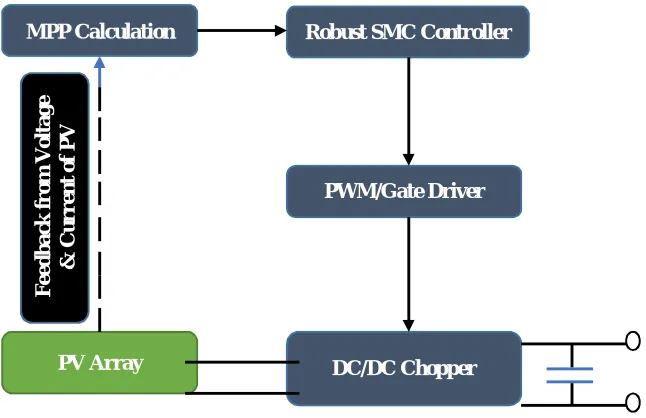
Figure 2: Proposed Robust Controller i.e. SMC based MPPT Approach
PV Array No 1 DC/DC Chopper DC/AC Inverter No. 1 Controller Inverter No. 1 Controller P C C M ic r o -G ri d
Feedback from O/P Voltage & Line Current Feedback from
DC Bus Voltage Feedback from Voltage
& Current of PV
L-C Filter
Z
1Lo ad -1 Lo ad -2 Lo ad -3 ES S Inverter Of ESS ESS Inverter Controller PV Array No 2 DC/DC Chopper Controller Feedback from Voltage
& Current of PV
DC/AC Inverter No. 2 Inverter No. 2 Controller Feedback from
DC Bus Voltage
Feedback from O/P Voltage & Line Current
L-C Filter
Z
2
MPP Calculation Robust SMC Controller
[image:3.612.146.469.489.698.2]A. Proposed MPPT Approach Based on Robust Back Stepping Sliding Mode Control
As above depicted figure 2 shows that the robust control technique i.e. SMC based MPPT approach for every PV module system. In this section describe an optimal approach based i.e. SMC which depicted in the figure 4.12. This new robust control approach totally based on an output voltage and current of the PV module system, a maximum peak point i.e. MPP found by the proposed module system and then proposed robust controller i.e. SMC control the DC/DC converter duty cycle, MPP tracked.
B. Calculation for MPP
An output voltage VPV and current IPV are applied to the unit of MPP so this unit has calculated the maximum power point of the
proposed system module. As the V-I characteristics, according or referring to this figure or characteristics the corresponding voltage Vm and also corresponding current Im calculated respectively, after that the proposed robust controller i.e. SMC enforces the converter (DC/DC converter) to follow this point. As maximum power point MPP is a point where the following condition met;
=
For find-out the PV output impedance considering the following relation;
=
Generally or commonly the PV output impedance is pure resistive so can again written as; =
Thus;
= + =
The solution goes non-trivial to the above equation is;
+ =
The open circuit and short circuit characteristics of the PV module system and solving these equation the voltage and current at maximum power point MPP i.e. Vm and Im are obtained or calculated.
V. SIMULATION RESULTS
In this section first compare the results between diesel generator plant, diesel generator plant 1, and PV array module system on the basis of linear and non-linear load then getting better results among of them compare to the base research paper.
A. For Linear Load
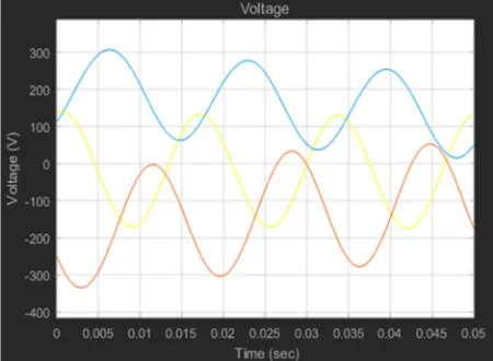
[image:4.612.193.418.544.709.2]When applied linear load at the load side of systems i.e. diesel generator plant, diesel generator plant-1 and PV array module system. In this case diesel generator plant for linear load and PV array module system provided better outcome voltage profile as compare to the normal diesel generator plant-1. Between these two diesel generator plant and PV array system module, the PV array module system provided the better voltage profile with better amplitude.
Figure 4: Output Voltage of Diesel Generator Plant for Linear Load
Figure 5: Output Voltage of PV Module for Linear Load
B. For Non-Linear Load
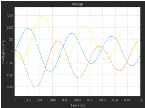
Figure 7: Output Voltage of Diesel Generator Plant for Non-Linear Load
Figure 8: Output Voltage of PV Module for Non-Linear Load
When applied non-linear load at the load side of systems i.e. diesel generator plant, diesel generator plant-1 and PV array module system. In this case diesel generator plant for non-linear load and PV array module system provided better outcome voltage profile as compare to the normal diesel generator plant-1. Between these two diesel generator plant and PV array system module, the PV array module system provided the better voltage profile with better amplitude.
VI. CONCLUSION
Micro-grids will have important role in future electrical power systems, since they can offer improved service reliability, better economy, and reduced dependency on local utility. As micro-grids are being more commonplace, the need for soft synchronization techniques is being more evident.
The simulation results confirmed that the new approach could reduce the frequency and power oscillations and keep the micro-grid robustly stable during the long network delays or changes in the system parameters.
REFERENCES
[1] Ali Akhavan, Hamid Reza Mohammadi, and Josep M. Guerrero, “Modeling and Design of a Multivariable Control System for Multi-Paralleled Grid-Connected Inverters with LCL Filter”, in International Journal of Electrical Power & Energy Systems. IEEE Transaction January 2018.
[2] B. Kanaga Sakthivel and Dr. D. Devaraj, “Modelling Simulation and Performance Evaluation of Solar PV-Wind Hybrid Energy System”, 978-1-4799-7678-2/15/$31.00 © 2015 IEEE.
[3] Xiaoqiang Li, Xiaojie Wu, Yiwen Geng and Xibo Yuan, “Wide Damping Region for LCL-Type Grid-Connected Inverter with an Improved Capacitor-Current-Feedback Method”, 10.1109/TPEL.2014.2364897, IEEE Transactions on Power Electronics 2014.
[4] Dongsheng Yang, Xinbo Ruan, and Heng Wu, “Impedance Shaping of the Grid-Connected Inverter with LCL Filter to Improve Its Adaptability to the Weak Grid Condition”, DOI: 10.1109/TPEL.2014.2300235, IEEE Transactions on Power Electronics · November 2014.
[5] Jinming Xu, Shaojun Xie and Ting Tang, “Active Damping-Based Control for Grid-Connected LC L-Filtered Inverter with Injected Grid-Current Feedback Only”, Pp. 4746-4758, IEEE Transactions on Industrial Electronics, Vol. 61, No. 9, September 2014.
[6] Shao Zhang, Shuai Jiang, Xi Lu Baoming Ge and Fang Zheng Peng, “Resonance Issues and Damping Techniques for Grid-Connected Inverters with Long Transmission Cable”, Pp. 110-120, IEEE Transactions On Power Electronics, Vol. 29, No. 1, January 2014.