in the image are complex to model, and the edges belonging to each selected area for message embedding are considered as noisy area for embedding. It is seen that embedding in edge pixels of image leads to changes in edges of the stego image. Thus, quality of the image is reduced. To improve quality of image as well as message payload capacity, area for message embedding is identify before message embedding using surrounding pixels intensity value difference. In addition to that, to provide higher security use of cryptography tech-niques is obvious. Furthermore, random pixel block selection for message embedding using pseudorandom generator and use of stego key boost the security of hidden message.
Message bits are embedded in the cover image using parity and substitution based image steganography algorithm in following steps [4].
1) Read the entire message from text file.
2) Convert message’s character stream in binary data stream using UNICODE conversion. Let M is a n-bit secret message represented as
M ={mi|0≤i≤n, mi∈ {0,1}} (1)
3) Enter the 16-bit stego key K.
4) Generate cipher binary data stream after encoding binary data stream using AES encoder and stego key. M0 is cipher data stream generated after encryption
M0={m0i|0≤i≤n, mi∈ {0,1}} (2)
5) Acquire the gray scale or color image as cover object. LetC is the cover image which has a totalNC×MC×
LC pixels represented as
C={Xijk|0≤i≤MC,0≤j ≤NC,0≤k≤LC}
(3) where,Xijk∈ {0,1, ...255}
6) Find out 2 ×2 non overlapping pixels blocks which are most suitable for message embedding and generate
2×2 pixels block location databaseD where message bits probably can embed based on their pixel value difference. Set the T hresholdmin value in such way
that, enough 2×2 pixels block location generated to embed secret message.
D={Da|0≤a≤l} (4)
where,l is a length of message database.
7) Randomly select location Da in the range 0 < a < l
from location database D for 8 bit message message embedding.
8) Read 8 bits of cipher binary data X =
x7x6x5x4x3x2x1x0 from cipher stream for data
embedding.
9) Select 4 bits of cipher binary data stream x3x2x1x0
and embed using pixel value difference embedding al-gorithm.
10) Select another 4 bits of cipher binary data stream x7x6x5x4 and changed the least significant bit (LSB)
value of pixel P(x, y), P(x, y+ 1), P(x+ 1, y) and
P(x+ 1, y+ 1) respectively using pixel parity based message encoding algorithm.
11) Repeat step 7, 8, 9, 10 until all cipher binary data stream of message and 16-bit stop flag1111111111111111has been embedded.
12) Save image data as a stego image(S) and transmit over channel.
B. Universal blind steganalysis
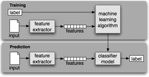
[image:2.612.315.567.270.400.2]Universal blind steganalysis can be considered as a clas-sification problem. In general, clasclas-sification is dividing a set of many possible object into disjoint subsets where is subset forms a class. Usually, the pattern recognition techniques are used to resolve classification problem. Pattern recognize techniques are used to identify complex pattern form given training sample and making intelligent decisions for testing sample.
Fig. 2. SVM classifier system
Universal blind steganalysis examines the characteristics of images which is used for training purpose and determine whether this characteristics exhibit as abnormality in test image. As a result of that, classifier should be able to decide the class cover or stego in which the test image belongs. Hence the problem of blind steganalysis can be considered as a binary classification problem. The general framework of the blind steganalysis is shown in figure 2.
In early stage of blind steganalysis research, image quality metrics, moments of image statistic histograms and wavelet decompositions are used as features. More recent features include markov empirical transition matrix, co-occurrence ma-trix and moment of image statistic from spatial and frequency domains. The features used for blind image steganalysis in this decade available on Binghamton University’s website. Among all of available feature extractor source code, SPAM features [5] set is used in this experiment. SPAM feature set is selected because SPAM feature set is highly precise and more appropriate for support vector machine classifier.
labels feed in to classifier for training purpose. Once classified is trained it works as an intelligent machine which can catego-rize the probably correct class of test (unknown) image based on the given features of test image. For practical steganalysis, main intend to identity the testing medium belongs to stego class or the cover class. When applying image steganalytic method to n image data set of cover image and stego image for detection, There are four possible situations, leftmargin=*
1) Stego medium is correctly detected as stego and it is referred asTrue Positive(TP)
2) Stego medium is incorrectly detected as cover and it is referred asFalse Negative(FN).
3) Cover medium is correctly detected as cover and it is referred asTrue Negative(TN).
4) Cover medium is incorrectly detected as stego and it is referred asFalse Positive(FP).
COVER IMAGE STEGO IMAGE
TRUE
FALSE
NEGATIVES POSITIVES
(TN)
(FP)
FALSE
TRUE
NEGATIVES
POSITIVES
(FN)
(TP)
NUMBER OF DETECTED NUMBER OF DETECTED
COVER IMAGE(DC) STEGO IMAGE(DS)
COVE R IMA G E(T C ) STE G O IMAGE(T S )
TRUE TYPE
DETECTED TYPE
COVER IMAGESTEGO IMAGE NU
MBE
R OF T
RU
E
NU
MBE
R OF T
RU
[image:3.612.77.265.265.431.2]E
Fig. 3. The confusion matrix
The results of test are represented in form of2×2matrixas as shown in figure and it is calledConfusion Matrixas shown in figure 3. Based on confusion matrix some evaluation matrix can be defined as mention below.
True Positive Rate(T P R) = T P
T P +F N (5)
False Negative Rate(F N R) = F N
F N+T P (6)
False Positive Rate(F P R) = F P
F P +T N (7)
True Negative Rate(T N R) = T N
F P+T N (8)
Accuracy= T P+T N
T P +F P+F N+T N (9)
Precision= T P
T P +F P (10)
III. PERFORMANCEEVALUATION
For experimental evaluations of the steganography method, the cover and stego image databases with different sizes are used. The message embedding rate is chosen to generate stego image as per the requirement of the experiment. Prior to the experiments, using MATLAB program the cover images and stego images datasets are divided into training and a testing set of equal sizes, with the same number of cover and stego images. Thus, it is ensured that images in the testing set were not used in any form during the training process or conversely. There is a SVM based classifier use with a gaussian kernel. This classifier must be adjusted to provide optimal results. In addition to that, the SPAM features [5] extraction method is using to extract image features and those features set will be used by SVM classifier. The SVM classifier produces output in form of confusion matrix. For experiment, stego images dataset is generated using 0.01 bpp, 0.05 bpp, 0.1 bpp and 0.2 bpp message embedding rates. Each stego images dataset is jointly used with cover images dataset for classification. Output produced by the SVM classifier for different message embedding rate are shown in figure 4, 5, 6 and 7.
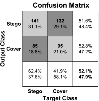
Fig. 4. Confusion matrices of proposed algorithm for 0.01 bpp message payload
[image:3.612.344.533.317.510.2]Fig. 5. Confusion matrices of proposed algorithm for 0.05 bpp message payload
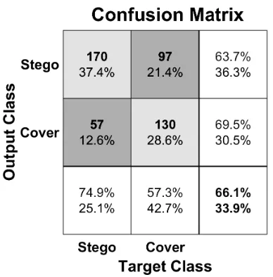
Fig. 6. Confusion matrices of proposed algorithm for 0.1 bpp message payload
from the security point of view. As shown in figure 6, for message embedding rate 0.1 bpp overall classification accuracy is 66.10% which is good indication for proposed steganography algorithm. In other words, when 52000 message bits are embedded in the image SVM classifier does not detect presence of messier bits in image because lower accuracy of the classifier is not consider as good performance of the classifier after training. It is also true that, once message embedding rate is increase over all accuracy of classifier is also increased it can be easily seen in figure 7.
[image:4.612.78.272.288.485.2]It is worth to say proposed steganography algorithm per-forming stupendous based on above discussion. Comparison with standard algorithms is required to prove it. Table I present comparison of proposed algorithm with F5 [7], MB1 [3]and Outguess [6]. Here comparison performed with frequency
Fig. 7. Confusion matrices of proposed algorithm for 0.2 bpp message payload
TABLE I
SVM CLASSIFIER DETECTION RATE COMPARISON OF PROPOSED ALGORITHM WITH OTHER ALGORITHMS
Rate Algoritham TP FN FP TN Accuracy
0.05 bpp
Outguess [6] 90.1 9.9 12.4 87.6 88.8
F5 [7] 57.0 43.0 41.4 58.6 57.8
MB1 [3] 82.0 18.0 20.6 79.4 80.7
Proposed 55.6 44.4 45.8 54.2 54.9
0.1 bpp
Outguess [6] 96.5 3.5 5.4 94.6 95.5
F5 [7] 70.2 29.8 31.9 68.1 69.1
MB1 [3] 93.3 6.7 8.8 91.2 92.2
Proposed 64.8 35.2 42.8 57.2 61.0
0.2 bpp
Outguess [6] 98.3 1.7 2.80 97.2 97.7
F5 [7] 88.3 11.7 14.2 85.8 87.0
MB1 [3] 97.8 2.2 3.3 96.7 97.2
Proposed 98.2 1.8 4.4 95.6 96.9
domain algorithm instead of spatial domain algorithm. It is widely known that, spatial domain algorithm provide higher payload capacity and frequency domain algorithm provide higher security against message detection attack. Past results shows that proposed algorithm has a higher payload capacity as compared to other algorithm. Now, it is time to prove that proposed algorithm provided better security against message detection attack. Statics of table I shows that for 0.05 bpp and 0.1 bpp message embedding rates proposed algorithm provide better security compare to F5 [7], MB1 [3] and Outguess [6] algorithm. For 0.5 bpp performance is proposed algorithm is close to MB1 [3]and Outguess [6] algorithm but F5 [7] algorithm provide better security for this case.
[image:4.612.315.561.322.445.2]and cover image class. This problem is resolved by Receiver Operating Characteristic (ROC) curve.
The steganography security under practical steganalyzers defined as following:
• A Steganography system is said to be γ secure with respect to steganalyzer
if |T P R−F P R|≤γ , where 0≤γ≤1.
• A steganography system is said to be perfectly secure with respect to steganalyzer
if γ= 0.
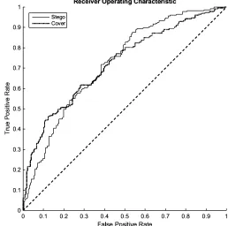
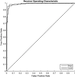
It is also represented in graphical form byReceiver Operat-ing Characteristic(ROC) performance curve of steganography system. Basically, ROC is curve of True Positive Rate Vs False Positive Rate. Figures 8, 9, 10 and 11 shows ROC curves of stego images when message embedding rate is 0.01 bpp, 0.05 bpp, 0.1 bpp and 0.2 bpp. For this experiment, training and testing images are selected randomly form cover and stego image dataset using MATLAB program and may be in unequal size. Moreover, 70% images are used for training purpose and 30% of images are used for testing purpose.
[image:5.612.314.566.48.312.2]Any steganography system can get the point on left bottom (T P R= 0 ,F P R= 0) and hence classifying everything as negative; similarly any steganography system can get the point on top right (T P R= 1,F P R= 1) and hence classifying as positive. When T P R=F P R, message detection probability is 0.5 and point on diagonal line. The steganography system is said to perfectly secure if we can get point on left top (T P R= 1,F P R= 0).
Fig. 8. ROC curves of steganography algorithm for 0.01 bpp message payload
[image:5.612.309.567.347.603.2]It is clearly seen in figure 8 and 9, at lower message embedding rate ROC curves of stego and cover images class
[image:5.612.49.304.403.667.2]Fig. 9. ROC curves of steganography algorithm for 0.05 bpp message payload
Fig. 10. ROC curves of steganography algorithm for 0.1 bpp message payload
Fig. 11. ROC curves of steganography algorithm for 0.2 bpp message payload
Fig. 12. ROC curves comparison of the proposed algorithm with F5, LSB, LSB±and MB algorithms
chance of correct classification of class appreciably increased which easily seen when message embedding rate is equal to 0.2 bpp in figure 11.
It also compares ROC of proposed algorithm with F5 [7], LSB [8], LSB± [9] and MB [3] image steganography al-gorithm curves as shown in figure 12. For ROC curve comparison, message embedding rate 0.1 bpp has been set. Figure 12 undoubtedly indicate proposed algorithm is secured compare to F5 [7], LSB [8], LSB±[9] and MB [3] algorithms because ROC curve of proposed steganography algorithm is
near to the ideal characteristic curve in compare to other algorithm. Finally, proposed image steganography algorithm performed stupendous in terms of security against universal blind steganalysis.
IV. CONCLUSIONS
Universal blind steganalyzer performance for security anal-ysis plays vital role. For lower message embedding rate, ROC curves of stego and cover images class are too close to the ideal characteristic curve which is the indication of random guessing. Hence, SVM classifier does not classify correct class of stego or cover image because true positive rate and true negative rate are smaller. Once message embedding rate is increased over all accuracy of classifier is also increased and ROC curve moves away from the ideal characteristic curve. ROC curve comparison demonstrates that steganography al-gorithm is more secure compare to F5, LSB, LSB±and MB algorithms. After the considering above facts, performance of pixel parity and substitution based image steganography algorithm is “stupendous”in terms of security.
In future work, Larger image database steganalysis should be performed to verify that hidden message bits in the stego image are not detected by universal image blind steganalysis technique and different feature sets are used in them. Targeted steganalysis frame work should be implemented to test the image steganography algorithm provide better security in com-pare with other well known image steganography algorithms. Hidden message length estimation is an emerging field in steganalysis world. If image is successfully detected as stego image than applied message length estimation techniques to know the length of hidden message. If algorithm is suc-cessfully pass the above mention security test than hardware version should be implemented for higher speed of operation.
REFERENCES
[1] David Kahn.The History of Steganography. First International Workshop, Cambridge, U.K., Lecture Notes in Computer Science. Springer-Verlag Berlin Heidelberg, 1996.
[2] D.B. Rawat. Security, Privacy, Trust, and Resource Management in Mobile and Wireless Communications. Advances in Information Security, Privacy, and Ethics:. Information Science Reference, 2013.
[3] N. Johnson, Z. Duric, and S. Jajodia.Information Hiding: Steganography and Watermarking-Attacks and Countermeasures: Steganography and Watermarking - Attacks and Countermeasures. Advances in Information Security. Springer US, 2012.
[4] Patel Chiragkumar B and Shah Saurin R. Parity and substitution based novel image steganography algorithm.International Journal of Computer Applications in Engineering Sciences, 5(1):10–14, 2015.
[5] T. Pevny, P. Bas, and J. Fridrich. Steganalysis by subtractive pixel adjacency matrix.Information Forensics and Security, IEEE Transactions on, 5(2):215–224, June 2010.
[6] Niels Provos. Defending against statistical steganalysis. InUsenix security symposium, volume 10, pages 323–336, 2001.
[7] Andreas Westfeld. F5 - a steganographic algorithm. 2137:289–302, 2001. [8] Xin Liao, Qiao yan Wen, and Jie Zhang. A steganographic method for digital images with four-pixel differencing and modified lsb substitution.
Journal of Visual Communication and Image Representation, 22(1):1 – 8, 2011.