Abstract ─ In this paper an approach based on an evolutionary algorithm to design combinational logic circuits with minimum number of Reed Muller units is suggested. Since replication of the same unit reduces the implementation cost of VLSI systems, a single control line Reed Muller universal Logic module (RM ULM) alone is used for the design. Any Boolean function can be realized with this method using any optimization algorithm. Here Genetic Algorithm (GA) is used as the optimization tool.A modification has been made on Davio decomposition technique and it has been observed that the circuits evolved are of lesser complexity and are superior to the circuits in traditional method in terms of power, area and delay.
Index Terms— Combinational logic circuits, Genetic Algorithm, Reed Muller ULM, Davio decomposition technique
I. INTRODUCTION
SE of integrated circuits in high performance
computing, telecommunications, consumer electronics etc. is growing at a very high rate with implications in cost effective design. For optimal design of electronic circuits, evolutionary design is a viable alternative. Evolutionary Algorithm is the most important feature in evolvable hardware applications. The algorithm needs to generate optimal circuits, which in turn have to be implemented on a programmable device.In the design of digital circuits, arriving at the minimal function is of great significance. Using an optimized design the complexity of the circuit can be reduced, thereby reducing the power consumption and cost. Major design criteria involve the delay of the circuit and the area of the chip which directly determines the manufacturing cost. Also power dissipation plays a major role on the packing and cooling cost of the system involved.
Conventional methods like Karnaugh map and Quine McCluskey do not support the use of XOR, XNOR, or any of the basic building blocks like multiplexers or Reed Muller Logic Modules. . Any Boolean expression can be realized using universal logic modules like 2-1 multiplexer
Manuscript received January 18, 2015; revised February 24, 2015. Vijayakumari C K. is with the Department of Electrical Engineering, Rajiv Gandhi Institute of Technology, (Government Engineering College) Kottayam, Kerala, India.(phone: 0481-2506953; fax: 0481-2506153; (e-mail:[email protected]).
Mythili P is with the Division of Electronics, Cochin University of Science &Technology, Kochi, Kerala, India(email: [email protected]).
Rekha K James is with the Division of Electronics, Cochin University of Science &Technology, Kochi, Kerala, India(email: [email protected]).
or 2-1 Reed Muller Universal Logic Modules,(RM ULM). Here, 2-1 R M ULM is used as the basic building block. Repeated use of the same unit reduces the manufacturing cost in VLSI implementation [4]-[5].
In comparison to the conventional Boolean logic XOR/AND based Reed Muller logic can be used to express any logic function, and has superior performance on circuits for arithmetic operations, parity check, telecommunication etc.[6]
While implementing a Boolean function, sub functions are useful. To build a hardware circuit for a function with n variables, the following identity is used.
F F′ Aj ′ xor F′′Aj (1) where F′ a F′′ are functions of n-1 variables.
Equation (1) represents Davio decomposition which is valid for realization of functions using Reed Muller units. This identity helps to reduce the original design problem to two simpler problems. Recursively applying such decomposition with every variable allows the process of synthesis to be reduced further to either literals or constants [7].
In this paper, GA based design of logic circuits using single control line RM ULM is proposed. The logic symbol of a 2-1 RM ULM is shown in fig. 1. Its behavior is described as
F= a
b.c (2)
Fig.1. Logic symbol of a 1-control line RM ULM
By standard implementation technique a function with n variables can be realized using 2n-1 units in
n levels. Any
technique which involves lesser number of modules or lesser number of levels is considered as an improvement in the design.
Genetic Algorithm Based Design of
Combinational Logic Circuits using Reed
Muller blocks
Vijayakumari C K, Mythili P, Rekha K James
II. RELATED WORK
A Genetic Algorithm based design of combinational logic circuits using minimum number of gates was proposed in [8]. Some of the circuits evolved were 2-1 multiplexer, 4 bit parity checker etc. The drawbacks were the problem of scalability and the time for convergence. In [9] these drawbacks were taken into account by using 2-1 multiplexer as the building block. In [5], design of combinational logic circuits using 2-1 multiplexer and Genetic programming was implemented. Only 4 variable parity circuits could be designed using this method which was a drawback. In [10], authors emphasized the use of RM circuits in certain applications. In [11], they proposed two different algorithms for the design of digital circuits using RM ULM, but it was not based on evolutionary technique. Boolean functions up to 4 variables were tested by them. In [12], authors realized an example of a combinational circuit using 2 variable Reed Muller Binary Decision Diagram and implemented using RM ULM.
In this paper an approach based on an evolutionary algorithm to design combinational logic circuits with minimum number of Reed Muller units is suggested.
The paper is structured as follows. Section III defines the problem, section IV discusses the formulation of algorithm for the evolutionary design, section V gives the implementation of logic circuits using the proposed method and section VI deals with the results and comparison with various methods and section VII concludes the paper.
III. PROBLEM DEFINITION
The problem is to evolve combinational logic circuits using GA with 2-1 RM ULM as the only building block. The goal is to evolve fully functional and optimal circuits, with minimum number of units. Once the fully functional circuit is obtained a check on redundancy is made so that idle units if any can be eliminated.
IV. ALGORITHM FORMULATION
In this work single output combinational logic circuits specified by a truth table is considered. Any combinational digital circuit can be realized using a cascade of RM ULM units.
To implement a function of n variables, conventional method needs n levels and 2n-1 units. eg., For a 3 variable
function, the circuit needs 7 units and 3 levels. There will be 4 units in the first level (bottom most level), 2 units in the second level and 1unit in the third level. For an optimal circuit, all the 7modules are not needed [3].
The functional description of the circuit to be evolved is encoded into chromosomes. Chromosomes are generated at random which holds the particulars regarding the presence of a unit, corresponding inputs, control signals and outputs as genes.
Fig. 2 shows the typical representation of a 10 bit chromosome for a unit (RM ULM) in the first level (bottommost layer) of the tree. Bit X1 verifies the presence or absence of an R M ULM and the combination of bits X2 to X6 represents the possible input signals to the RM ULM. The control signal is being determined by the combination of bits X7 to X9. X1=0 indicates the absence of the module.If“X2X3X4X5X6”=“000000”, then the input to the
unit is considered as ‘0, 0’and so on. Also the combination X7X8X9=“000” implies that the control input is ‘a’. The string “001” corresponds to ‘b’ and so on. If the randomly generated string is “1110110101”, it implies that an RM ULM exists with c and a’ as inputs and control signal as c’. Coding in a similar manner is being done for units in other levels also.
Fig.2 Chromosomal representation of a RM ULM in the first level
A. Selection process and Fitness Function
Search is carried out among the individuals generated at random. On the basis of their fitness value, they are reproduced to the next generation thereby selecting the strings from old population to new population. Roulette wheel selection technique has been adopted here. Genetic operators such as crossover and mutation are applied on these individuals so as to form a new population [13].
Fitness of chromosome is measured based on the percentage of correct outputs in response to the appropriate inputs [3]. Depending upon the proximity to the desired truth table fitness for each individual is calculated as
% FITNESS , 100 (3)
Where O1 is the evolved output, O2 is the desired output
and N is the number of rows in the truth table. A circuit satisfying all the outputs in the truth table is considered to be a 100% fit circuit. After evolving 100 % fit circuit, a check for redundancy of units is made and is eliminated to generate the optimal circuit.
V. PROPOSED METHOD
Every Boolean function can be expressed in the form of Reed-Muller (RM) expression using AND and XOR operators.
Basic theorems involved are x ⊕ x = 0; x ⊕ 1= x’; x ⊕ x’= 1; x ⊕ 0 = x ;
Conventional design of combinational logic circuits which is based on Davio decomposition technique permits the use of only same control signals to all the RM blocks in a level and the number of levels needed is equal to the number of variables involved in the function. A modification is being proposed so that circuits are evolved with minimum number of units and/or levels. The control signals need not be the same for all the units in a particular level. They are also generated at random and optimal solution is being achieved by using Genetic Algorithm.
alone or ‘c’ alone. But in the proposed method control signals are generated at random and need not be the same in a particular level. Circuits have been evolved for 2, 3, 4and 5 variable functions. Fitness was evaluated based on the fitness function mentioned earlier. Also redundant/idle units are eliminated so that circuits with minimum possible units are generated.
A. Experiments
The program was applied to several functions from the references including some benchmark functions and comparison has been made in terms of the number of units and levels for the generated circuits.
Example1.Three bit odd parity checker circuit F (a,b,c)=Σ (1,2,4,7)
The circuit generated for the 3 bit odd parity checker function is shown in fig. 3. It can be seen that the circuit needs only 2 units as compared to 7 units in conventional method. Also the number of levels which decides the delay is reduced from three to two.
Example2. F (a,b,c)=Σ (3,5,6)
The evolved circuit for this function is shown in fig. 4. The circuit needs only 3 units, but the conventional method by Davio decomposition technique needs 7 units, thus saving 4 units.
Example 3. F(a,b,c,d)= (c+(d⨁a))'+(b⨁(ad'))
is a standard benchmark function with 4 inputs and one output.
The circuit generated for this function is shown in fig.5, which has only 4 units, thus saving 11 units as compared with standard implementation.
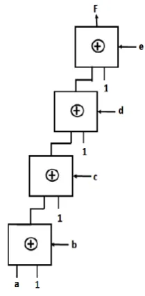
Example4. Four bit odd parity checker F(a,b,c,d)= Σ (1,2,4, 7,8,11,13,14)
The evolved circuit shown in fig. 6 for the function for odd parity has only 3 units and 3 levels, whereas the circuit by conventional method needs 15 units and 4 levels. It is very difficult to evolve circuits for odd parity functions using multiplexers [5]. Here the circuit converges very fast as it involves XOR operations.
Fig.4. circuit for F (a,b,c)=Σ (3,5,6)
Fig.5. Circuit for Example 3
Example5. The next circuit is also a standard benchmark function of 5 variables -xor5.pla.
The evolved circuit shown in fig.7 has only 4 units and 4 levels. Conventional method needs 31 units in 5 levels. Here the number of levels also got reduced so that the delay involved is also reduced.
Fig.3. Circuit for 3 bit odd parity checker
Example6. F (a,b,c,d) = Σ (1,2,3,5,7,8,12)
This function is an example taken from [12] where the synthesis was made using 2VRMBDD and GA, which required 6 units and 4 levels. In [3] also the circuit was realized using 6 units and 4 levels. With the proposed method, the circuit is implemented using 4 units and 4 levels as shown in fig.8.Thus a saving of 11 units with respect to the traditional method and 2 units in comparison to[12] has been achieved.
VI. RESULTS
The parameters selected for GA were, crossover rate=0.7, mutation rate=0.3, Population size depends on the complexity of the circuit. As the proposed method is using only RM ULM, circuits with XOR operations converge much faster and the size of populations can be made less. Roulette wheel selection technique has been used for selecting the individuals for crossover. The simulation was done in MATLAB R2012a and analysis of power, area and
delay of the evolved circuits have been done by using Synopsys Design Compiler. The program was run on Intel i5duo processor (4.00 GHz).
Each result from GA is taken after running the program 15 to 20 times in order to ensure the quality of the circuit.
Fig.9 and fig.10 show the power consumed and the delay Involved by the evolved circuits by standard implementation, method specified in [3] and the proposed method respectively.
It is obvious that the power and delay got reduced significantly in the circuits generated by the method proposed.
Functions implemented F1 (a,b)=Σ(1,2) F2 (a,b,c)=Σ(0,4,6,7) F3 (a,b,c)=Σ(1,2,4,7)
F4 (a,b,c,d)= Σ(0,4,6,7,8,12,14,15) F5 (a,b,c,d,e)... xor5
Table I shows the comparison of results of the proposed method in terms of number of modules for the above functions with standard implementation technique and the methods proposed in [3]. Method III in [3] is found to be more efficient as compared to other methods. Hence comparison has been made only with standard method and method III of [3]. It is evident that there is a significant reduction in the hardware as the number of units is less.
0 0.2 0.4 0.6 0.8 1 1.2 1.4
F1 F2 F3 F4 F5
Delay
in
nano
seconds
standard
Method III[3]
proposed method 0
20 40 60 80 100 120 140 160
F1 F2 F3 F4 F5
Standard
Method III[3]
[image:4.595.109.214.51.265.2]Proposed
Fig.8. Circuit for F (a,b,c,d) = Σ (1,2,3,5,7,8,12) Fig.7. Evolved circuit for xor5 function
[image:4.595.310.535.179.513.2]Fig.10. Delay in various methods
[image:4.595.93.191.412.631.2]Table II depicts the % reduction in area involved in the proposed method.
TABLE I
COMPARISON OF NUMBER OF UNITS AND LEVELS
TABLE II
COMPARISON OF AREA INVOLVED FOR CIRCUITS IN EACH METHOD
The power consumption and number of units for the circuits in the proposed method and the method in [12] have been analyzed and summarized in tables III and IV respectively.
TABLE III
COMPARISON OF POWER CONSUMPTION
` TABLEIV COMPARISON OF AREA
Tables III and IV reveal that the area and power consumption for the circuits in the proposed method reduces significantly as compared to the traditional method and the method proposed in [12].
VII. CONCLUSION
By evolutionary methods combinational logic circuits have been designed and synthesized using 2-1 RM ULM as the basic building block. On synthesis, it was found that the circuits evolved by this approach are superior to the design by traditional methods. We have used VHDL to describe the developed design and the Synopsys design compiler to synthesize the design. Number of modules, area,delay and power consumption of the evolved circuits were reduced significantly, which ensures better performance.
REFERENCES
[1] Slowik and Michal Bialko,. “Evolutionary Design of combinational Digital Circuits: State of the Art, Main Problems, and future Trends,” Proceedings of the First International Conference on
Information Technology 19-21, May 2008, pp. 1-6.
[2] C. Coello and A. Christianses, ”Use of Evolutionary techniques to automate the design of Combinational Circuits”, International Journal of Smart Engineering System Design, Elsevier Science, Vol. 2, No. 4, June 2000, pp. 299-314.
[3] C.K Vijayakumari, P.Mythili, Rekha K.James, Akhil Kumar ”Optimal design of Combinational logic Circuits using Genetic Algorithm and Reed Muller Universal Logic modules", IEEE proc. of international Conference on Embedded systems ICES 2014, pp. 1-6.
[4] A.H Aguirre, Bill P Buckles, C A Coello Coello, ”Gate level synthesis of Boolean functions using Binary multiplexers and Genetic Programming” Congress on Evolutionary Computation, IEEE Service Center, Piscataway, New Jersey, July 2000, pp. 675—685.
[5] A.H Aguirre and C A Coello Coello, ”Using Genetic Programming and multiplexers for the synthesis of Logic Circuits” Proceedings of 2003 NASA/ DoD Conference on Evolvable Hardware, 2006, pp.46-53.
[6] B. A. Al Jassani, N Urquhart,A E A Almaini, "Manipulation and optimization techniques for Boolean logic", IET Comput.Digit.Tech.,2010,vol.4,isue.3, pp. 227-239.
[7] Khalid Faraj and AE A Almaini,” Optimal polarity of Dual Reed Muller expressions", 7th WSEAS International Conference on Microelectronics, Nanoelectronics, Optoelectronics (MINO '08), Istanbul, Turkey, May 27-30, 2008, ISBN: 978-960-6766-65-7, ISSN: 1790-5117,pp. 45-52. [8] Cecilia Reis, J. A. Tenreiro Machado, and J. Boaventura
Cunha, F No: of variabl es SI
Method III in[3] Proposed Method No: of units No: of units No. of Levels No: of RM ULMs No. of levels
1 2 3 2 2 1 1
2 3 7 3 3 2 2
3 3 7 3 3 2 2
4 4 15 4 3 2 2
5 5 31 5 5 4 4
F No. of variabl es Standard impleme ntation Method III in [3] Proposed method Total
Area Total Area %
Saving Total Area % Savi
ng
1 2 59.834 38.420 35.78 38.42 35.78
2 3 138.031 59.210 57.11 59.01 57.24
38.031 98.589 28.57 78.918 42.8
4 4 299.491 78.88 73.67 38.28 87.21
5 5 604.142 98.341 83.7
79.21 86.89
Power consumed Boolean Function Standard implementation Method in[ 12] Proposed method
4 input function F(a,b,c,d)=∑ (1,2,3,5,7,8,12)
71.535μw 28.86 μw 15.766 μw
Area in number of units
Boolean Function Standard implementation Method in[12 ] Proposed method
4 input function F(a,b,c,d)=∑ (1,2,3,5,7,8,12)
299.491 118.29 78.88
”Evolutionary design of combinational logic circuits”,Journal of Advanced Computational Intelligence and Intelligent Informatics Vol.8 No.5, 2004, pp. 507-512.
[9] Vesselin K. Vassilev, Julian f Miller”, Scalability Problems of digital Circuit Evolution Evolvability and Efficient Designs", Proceedings of the 2nd NASA/DOD Workshop on Evolvable Hardware, Los Alamitos, CA pp. 55–64.
[10]Khalid Faraj, "Fast Coding of Dual Reed Muller Expressions",
Proc. of the 6th WSEAS International conference on Engineering education, pp. 212-219. ISSN 1790-2769. [11]Shahana T K, Rekha K james,K Poulose Jacob,Sreela Sasi,
"Automated synthesis of Delay Reduced Reed Muller Logic Module Networks,International Conference on Embedded systems and Applications 2008, pp105-110.
[12]OH,P.and Almaini A E A,”2 Variable Reed Muller Binary Decision Diagrams”,Proc of the 6th Int.Conf. on
Electronics,Hardware,Wireless and optical
communications,Greece,Feb 2007,pp.197-202.