© 2019, IRJET | Impact Factor value: 7.211 | ISO 9001:2008 Certified Journal
| Page 906
A STUDY ON SEISMIC ANALYSIS OF RC FRAMED STRUCTURES ON
VARYING SLOPE ANGLES WITH & WITHOUT SHEAR WALLS
Vinayakumar R
1, Chetan Gonni S
21
Post Graduate in Structural Engineering, BIET College, Davanagere
2
Asst. Professor, M. Tech Structural Engineering, BIET College, Davanagere-577004, India
---***---Abstract - The structures are usually constructed on flat ground, however, due to the lack of flat grounds usually hilly regions for construction task have been preferred. Since, construction of framed structures on sloping grounds gives variety of structural performance than the flat grounds, since these structures are unequal in universe consequently, attract huge amount of shear force and torsional moments and shows unsymmetrical distribution due to differing in column lengths. In this existing study, performance of G+10 building on varying
sloping angle i.e. 00,11.250, 22.50, 450 to be studied for without
and with shear walls at corners (Case 1) and both corner & edges (Case2) for a seismic intensity of 0.24 (Zone IV). The modeling and analysis of the RC framed structures has been done by using ETABS. To study the effect of varying column length in bottom storey by increasing sloping angle by both equivalent static and response spectrum analysis as per Indian standards codes. The results to be obtain in form of Base Shear, Story Shear, Story Displacement, Story Drift ratios for all cases of with shear walls (Case 1 & Case 2) and without shear walls for all the incremental slope angles have been studied.
Key Words: Slope Angle, Shear Walls, Base Shear, Story Shear, Story Displacement, Story Drift and ETABS.
1. INTRODUCTION
Since past years ago, huge quantity of material bunch combined to made Earth. This bunch of materials exhibits huge quantity of heat and slowly as the earth warmed down, the massive and medium material sink to the center and delicate or weightless materials climbed to the top. The converted earth made up of the inner core of the radius 1290 km, the outer core of thickness 2200 km, the mantle of thickness 2900 km and crust of thickness 5 to 40 km. These layers of cores induced by some variety of materials such as, inner core which is solid type of the core and it consists of massive metals like nickel and iron as the constituents and outer core which is liquid in form as the constituents as material, similarly main constituents of material for the mantle core is ability to flow and the crust constitutes the weightless or delicate materials like basalt and granites. In which the core has estimated temperature about 25000C as a pressure about 4 million atmosphere and density about 13.5 gm/c which is in contrast to 250C at 1 atmosphere and 1.5 gm/cc on the surface of the earth.
1.1 CONSTRUCTION ON SLOPING GROUND
Usually constructions of buildings on sloping ground are unequal in nature, due to this unequal nature design of these buildings are difficult on slopes and undulations on grounds. But at present generation growth of the population in this universe is tremendously increasing, which affects the basic requirements of the constructional activities like transportation and shortage in the availability of land, by considering all of these affects peoples are rapidly focused on sloped land like hill stations for their constructions, but construction on sloped grounds are rejected for constructional activities due to difficulty in transportation and effect of slopes on the structures. During the past earthquakes on hilly regions like sloped buildings undergo huge damage which directly cause the failure of the structure by collapsing, because building constructed on sloped grounds have varying column heights at the bottom stories, which leads to short columns more prone to seismic activity than the long columns.
1.2 OBJECTIVE OF THE STUDY
The objectives of the present study on seismic analysis of RC framed structure on the sloping ground for with and without shear wall are as follows:
1. To develop the RC framed structures on sloping ground having G+10 stories with an earthquake intensity of zone IV.
2. To develop the models by varying column length at the bottom story by increasing sloping angels such as 00 (Plane Surface), 11.250, 22.50, 450, respectively for without shear wall and with shear walls at corners and edges of the building with various cases which are listed in the next chapter (Chapter-3). 3. To perform the analysis of the developed RC frame
models by ESA & RSA as per IS 1893-2002. 4. To obtain the seismic parameters such as base
shear, story shear, time periods, story displacement and story drift by both ESA & RSA.
2. DATA FOR DEVELOPING THE MODEL
© 2019, IRJET | Impact Factor value: 7.211 | ISO 9001:2008 Certified Journal
| Page 907
developing 12 models of G+10 story with a plan [image:2.595.41.284.221.367.2]dimensions along X & Y axis, story heights and structural components which are beams, Columns, Slabs and Shear walls considered for the analysis of frame structures by the dimensions with the materials properties which are Grade of concrete and Grade of steel have been listed on Fallowing Table.
Table -1: Building Parameters for Analysis SL NO. PARAMETERS REMARKS
1 Plan Dimension 14 X 17.5 m
2 No. of Stories G + 10
3 Story Height 3.2m
4 Plinth Beam Height 1.75m 5 Size of Column 700 X 700 mm
6 Size of Beam 300 X 300 mm
7 Slab Depth 150 mm
8 Shear wall Thickness 200 mm
9 Grade of Concrete M30
10 Grade of Steel Fe 500, Fe 415
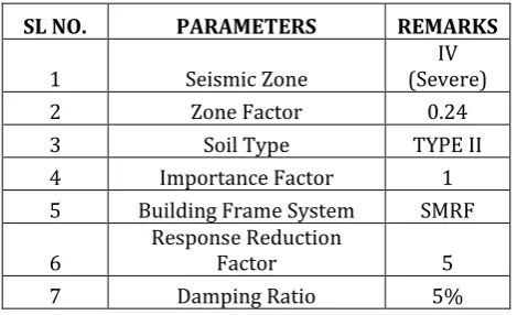
[image:2.595.45.280.442.585.2]2. Seismic parameters which are used for analyzing the framed structures are considered as per IS 1893-2002 (part 1) are listed below.
Table -2: Seismic Parameters for Analysis SL NO. PARAMETERS REMARKS
1 Seismic Zone (Severe) IV
2 Zone Factor 0.24
3 Soil Type TYPE II
4 Importance Factor 1
5 Building Frame System SMRF
6 Response Reduction Factor 5
7 Damping Ratio 5%
2.1 LOAD CALCULATIONS FOR DEVELOP THE MODLES a. Loads on slab:
1. Live load = 4 KN/m2. 2. Floor finish,
12mm vitrified tile = 0.012 x 24 = 0.29 KN/m2.
20mm backing mortar = 0.02 x 20.4 (density of cement plaster) = 0.408 KN/m2.
12 mm thick ceiling plaster = 0.25 KN/m2. TOTAL = 0.948 KN/m2.
Say, Floor finish = 1.5 KN/m2.
Floor finish on ground floor for parking = 2 KN/m2. Floor finish on terrace,
Water proof plaster = 0.150 KN/m2. 12mm ceiling plaster = 0.25 KN/m2.
Total = 0.4 KN/m2.
By considering extra load due water proofing as 2.6 KN/m2.
Then, Total floor finish on terrace = 3 KN/m2.
b. Load on beam:
Loads on Beams are self-weight and wall loads, self-weight of the beam is determined automatically by ETABS and wall loads can be assigned by manual calculation results which is calculated below.
Wall load calculations for beam, Thickness of wall considered, For exterior wall thickness =230mm. For interior wall thickness =150mm. Density of brick = 20 N/mm2. Height of parapet wall for terrace = 1.5m.
Exterior wall load calculation,
= 0.230 x (3.2-0.450) x 20 + 0.04 x (3.2-0.450) x 20.4 = 14.9 KN/m.
Interior wall load calculation,
= 0.150 x (3.2-0.450) x 20 + 0.04 x (3.2-0.450) x 20.4 = 10.5 KN/m.
Parapet wall load on terrace, = 0.230 x 1.5 x 20 + 0.04 x 1.5 x 20.4 = 8.12KN/m.
2.2 MODELLING TO 450 SLOPE ANGLE & ANALYSIS
a. Bottom Length Calculations: Sloping angle consider for model 4 is 450, and considering 1.5m as first column length, and remaining columns length can be calculated by,Tan 450 = 1, 1st column length=1.5m.
b. Fundamental natural period Calculation:
1. Without shear wall for both along X-direction and Y-direction,
Ta = 0.075*h0.75, Where h = 50.7 m. Ta = 0.075*50.70.75 = 1.42 s.
© 2019, IRJET | Impact Factor value: 7.211 | ISO 9001:2008 Certified Journal
| Page 908
Fig -1: Plan & Elevation for model with slope angle of 450without Shear walls.
Fig -2: Plan & Elevation for model with slope angle of 450 with Shear walls at corners.
Fig -3: Plan & Elevation for model with slope angle of 450 with Shear walls at corners and edges.
3. RESULTS & DISCUSSION 3.1 STORY SHEAR
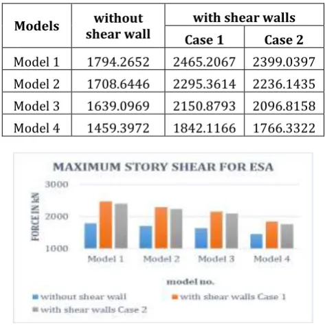
[image:3.595.315.552.220.459.2]It is defined as the lateral force acting on each story in horizontal direction during earthquake, and the maximum lateral shear should always maximum at the base of the building which is termed as the Base shear.
Table -3: Maximum Story Shear for ESA along X & Y Axis
Models shear wall without with shear walls Case 1 Case 2 Model 1 1794.2652 2465.2067 2399.0397 Model 2 1708.6446 2295.3614 2236.1435 Model 3 1639.0969 2150.8793 2096.8158 Model 4 1459.3972 1842.1166 1766.3322
[image:3.595.45.278.290.459.2]Chart -1: Maximum Story Shear for ESA
Table -4: Maximum Story Shear for RSA along X & Y Axis
Models shear wall without with shear walls Case 1 Case 2 Model 1 1794.2625 2465.1963 2399.0393 Model 2 1708.6402 2295.3544 2236.1358 Model 3 1639.0922 2150.8723 2096.8049 Model 4 1459.3919 1842.1151 1766.3289
[image:3.595.38.293.497.705.2] [image:3.595.318.551.508.750.2]© 2019, IRJET | Impact Factor value: 7.211 | ISO 9001:2008 Certified Journal
| Page 909
From Chart 1 & 2 represents the maximum story shearresults for varying slope angles of all the models with shear walls (Case 1 & Case 2) and without shear walls for both ESA & RSA along X & Y direction, Maximum story shear for Model 1 shows maximum values.
3.2 STORY DISPLACEMENT
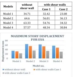
[image:4.595.308.558.53.245.2]The lateral displacement of each story due to the lateral forces from base of the building or structures is known as story displacement. Story displacement results for the structures with various cases for all the models as tabulated below.
Table -5: Maximum Story Displacement for ESA along X & Y Axis
Models shear wall without with shear walls Case 1 Case 2
Model 1 34.71 32.42 23.08
Model 2 64.6 56.01 36.13
Model 3 63.33 54.76 34.32
Model 4 57.57 48.34 30.84
Chart -3: Maximum Story Displacement for ESA Table -6: Maximum Story Displacement for RSA along X &
Y Axis
Models shear wall without with shear walls Case 1 Case 2
Model 1 28.068 26.684 19.186
Model 2 53.395 45.758 29.703
Model 3 55.86 46.41 31.51
Model 4 54.98 43.5 30.84
Chart -4: Maximum Story Displacement for RSA From Chart 3 & 4 represents the maximum story displacement results for varying slope angles of all the models with shear walls (Case 1 & Case 2) and without shear walls for both ESA & RSA along X & Y direction, Maximum story displacement for model 2 shows maximum values.
3.3 STORY DRIFT
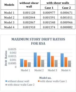
[image:4.595.38.288.285.550.2]It is defined as the drift of the one story with respect to the below story of the building and story drift limitation as per IS 1893-2002 is 0.004 times the story height. The story drift results for the structures with various cases for all the models as tabulated below.
Table -7: Maximum Story Drift for ESA along X & Y Axis
Models without shear wall with shear walls Case 1 Case 2 Model 1 0.001287 0.001137 0.000791 Model 2 0.002379 0.001888 0.001227 Model 3 0.002248 0.001788 0.00114 Model 4 0.00193 0.001516 0.000941
[image:4.595.44.559.462.729.2]© 2019, IRJET | Impact Factor value: 7.211 | ISO 9001:2008 Certified Journal
| Page 910
Table -8: Maximum Story Drift for ESA along X & Y AxisModels without shear wall with shear walls Case 1 Case 2 Model 1 0.001128 0.000977 0.000671 Model 2 0.002044 0.001591 0.001011 Model 3 0.002067 0.001548 0.000966 Model 4 0.001918 0.001374 0.000882
Chart -6: Maximum Story Drift Ratios for RSA From Chart 5 & 6 represents the maximum story drift results for varying slope angles of all the models with shear walls (Case 1 & Case 2) and without shear walls for both ESA & RSA along X & Y direction, Maximum story drift for all the models are within the limits as per IS 1893-2002 (Part 1) which is 0.004 times of the story height.
3. CONCLUSIONS
In this present study, seismic analysis of RC framed structures on varying slope angles for with and without shear wall have been modelled and analysis is done for ESA & RSA with ETABS and the results which are obtained is time period, base shear, story shear, story displacement and story drift. From the analysis results, the following conclusions have been made as fallows,
i. From the story shear results it has been observed that for both ESA & RSA as the angle of slope increase base shear of the structures decreases to 5% - 12% and the shear walls at corners having maximum base shear than the shear walls at both corners and edges.
ii. From the both ESA & RSA it has been observed that story shear values are goes on decreases at the top story and the slope angle increases story shear values decreases and shear walls at the corners
have maximum story shear than the shear walls at both corners and edges.
iii. Story displacement is observed to be maximum for ESA than the RSA for all models and it is maximum at the top story, as the slope angle varies displacement of the stories increases, but in case of model 4 it shows less displacement than the other models and it is observed to be displacement is maximum along Y-direction than the X-direction for both ESA and RSA analysis, they should be in allowable permissible limits, Displacement for the shear walls at corners positions have been observed to be maximum than the shear walls at both corners and edges positions, hence shear walls at both corners and edges positions are to be suitable location for structures on sloping ground.
iv. The story drift is observed to be maximum for ESA than the RSA for all the models, drift values increases as the slope angle increases, but in case of model 4 it shows less values than the other models and for the shear walls at corners having maximum story drift than the shear walls at both corners and edges positions of the structures, and it has been observed that for all the models story drift ratios are within permissible limits as per IS 1893-2002 (Part 1) clause 7.11.1.
v. From the present study, shear walls at both corners and edges positions gave lesser values in the results of time period, base shear, story shear, displacement and drift for all the models within the limitations provided from the IS 1893-2002 (Part 1), Hence shear walls at both corners and edges positions are to be suitable location for structures on sloping ground and safe against the seismic forces.
REFERENCES
[1] Likhitharadhya Y R and Praveen J V, “Seismic analysis of multi storey building resting in flat ground and sloping
ground”, International journal of innovative research in
science, Volume 05, Issue 06, Page 9786-9794, June 2016.
[2] Miss. Pratiksha Thombre and Dr.S.G. Makarande,
“Seismic analysis of building resting on sloping ground”,
Journal of emerging technologies and innovative research (JETIR), Volume 03, Issue 06, Page 296-300, June 2016.
[3] M.G. Kalyanshetti, “Seismic analysis of building resting on sloping ground with varying number if bays and hill
slopes”, International journal of engineering research &
technology (IJERT), Volume 02, Issue 12, Dec 2013.
[4] Naveen Kumar S M and Vasipalli Vamsi Krishna Reddy, “Analysis and comparison of step back RC frame building
© 2019, IRJET | Impact Factor value: 7.211 | ISO 9001:2008 Certified Journal
| Page 911
for research trends and innovative (IRJTI), Volume 02,Issue 09, Page 61-69, 2017.
[5] Rahul Manoj sing Pawar and S.B. Sohani, “Analysis of
setback step back building resting on sloping ground”,
International journal of scientific development and research (IJSDR), Volume 02, Issue 06, Page 577-584, June 2017.
[6] Roser J Robert and Ranjana M. Ghate, “Seismic analysis of
multistoried RCC building on sloping ground”,
International journal for research in emerging science and technology, Volume 03, Issue 12, Page 40-45, Dec-2016.
[7] Ravindra Navale and Dr. Sandeep Hake, et al., “Analysis of unsymmetrical building resting on sloping ground by
dividing in 2D frame”, International research journal of
engineering and technology (IRJET), Volume 04, Issue 07, Page 943-946, July 2017.
[8] Shivanand.B and H.S. Vidyadhara, “Design of 3D RC frame
on sloping ground”, International journal of research in
engineering and technology (IJRET), Volume 03, Issue 08, Page 307-317, Aug 2014.
[9] Umakant Arya and Aslam Hussain, et al., “Wind analysis
of building frames on sloping ground”, International
journal of scientific and research publications, Volume 04, Issue 05, May 2014.
[10]Vinod Kumar and H.S. Vidyadhar, “Analysis of 3D RC frame
on sloping ground”, International research journal of
engineering and technology (IRJET), Volume 04, Issue 09, Page 1176-1184. Sep 2017.
[11]Zaid Mohammad and Abdul Baqi, et al., “Seismic response
of RC framed building resting on hill slopes”, Science
direct procedia engineering 173, Page 1792-1799, 2016. BIOGRAPHIES
VINAYAKUMAR R Post Graduate Student Dept. of Civil Engineering BIET College, Davanagere.
CHETAN GONNI S Asst. Professor