© 2019, IRJET | Impact Factor value: 7.211 | ISO 9001:2008 Certified Journal | Page 1786
DESIGN OPTIMIZATION AND RAPID PROTOTYPE OF CAR FRONT DOOR
STRUCTURAL COMPONENTS
V.N. Fazil
1, Dr. A. Dhanapal
2, M. Raja Mohan
3,
E. Manopriya
41
PG Scholar, Department of Mechanical Engineering,
Sri Ramanujar Engineering College, Chennai, TN, India
2Principal, Department of Mechanical Engineering,
Sri Ramanujar Engineering College, Chennai, TN, India
3Head of the Department, Department of Mechanical Engineering,
Sri Ramanujar Engineering College, Chennai,
TN, India
4
Assistant professor, Department of Mechanical Engineering,
Sri Ramanujar Engineering College, Chennai,
TN, India
---***---Abstract -
In developing nations, the car manufactures arefocusing more on fuel-efficient cars due to increase in price of petroleum products. As the weight of the vehicle is related to the fuel efficiency, lowering the vehicle weight can achieve increase in mileage. The car door comprises around 10~15% of total vehicle weight and can be considered as one of major parts to be considered for optimization. The reduction in mass to increase the fuel efficiency can result in decrease in strength of door. Loss of stiffness of car can be sensitive to sag and over open performance of car. In addition, outer panel buckling is also sensitive to panel thickness incurred due to body leaning on car or during the car cleaning. The project focuses on understanding the existing conventional car door design, and to explore the potential optimization parameters to save the mass as this is the one area each designer in automotive industry is looking forward to increase the fuel efficiency and cost of manufacture. In most of the industries, the potential studies are carried out to optimize the parts, as some of the structures may not designed optimally during the product development phase. The reason for this can be due to the short timeline for the product release or change in performance target (lowered) due to studies like benchmarking or costing etc. In this study, the capability of virtual simulation (CAE) is used to evaluate the performance of the door structure and to optimize the parts. Another innovative trend in the automotive industry is the use of rapid proto-type techniques. Rapid proto-type model helps to understand the manufacturing feasibility and to have a feel of the part before actual tool development. In this study, we are exploring the easily available and cost effective rapid proto-type technique to develop a scaled proto-type model of one of the car components.
Key Words: Car door, Optimization, Cost, Weight, Fuel efficiency, Virtual simulation, CAE, Rapid prototype, Sag, Over-open.
1. INTRODUCTION
Doors are highly complex structures that contain just about everything that a car as a whole contains except for power train elements. Customers interact intimately with doors. Doors are one of the major components in a car, which provide easy access for passengers into the car. Doors also comprise both interior and exterior elements, causing them to be links between these two domains of the car. Many of the attributes conflict: for example, better water leakage and wind noise behavior will make it more difficult to close the door; better side intrusion protection will make the door heavier; better leakage around the glass makes it harder to raise the glass, requiring stronger motors, making the door heavier. Door system mainly consists of window glass, window regulator assembly, door latch, sealing and structural components of the door assembly. Traditionally these parts are designed, manufactured and procured separately.
1.1 Objective of the Project
© 2019, IRJET | Impact Factor value: 7.211 | ISO 9001:2008 Certified Journal | Page 1787
1.2 Project Flow Chart
Fig -1: Flow Process of Front Door Structural Components
2. DESIGN DETAILS & DIFFERENT LOAD CASES
2.1 Design Details
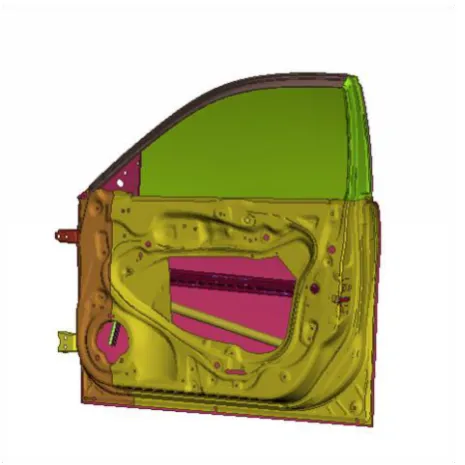
Door assembly and the other components considered shown in Figure 2, consists of inner panel, outer panel, belt reinforcements, hinges , impact beam etc
Fig -2: Front Door Assembly
2.2 Door parts considered for hinge side
optimization
Fig -3: Door Inner Panel
Baseline design is having Tailor welded inner panel design and the new design identified for robust optimization is single piece inner panel with hinge reinforcement , Robust optimization door properties considered for simulation
Table -1: Physical propertiesofBaseline door
S.No. Door Parts Material Thickness (mm)
1 Inner panel
(Thick / Thin) Steel 1.5/0.8
2 Tapping plate
(Upper / Lower) Steel 1.8/1.8
3 Hinges Steel 5
Table -2: Physical propertiesofNew design door
S.No. Door Parts Material Thickness (mm)
1 Inner panel Steel 0.8
2 Tapping plate
(Upper / Lower) Steel 1.2/1.2
3 Hinges Steel/Al 5
4 Hinge
Reinforcement Steel 1.5
2.3 Material Description
[image:2.595.309.562.109.257.2] [image:2.595.40.285.114.356.2] [image:2.595.47.280.487.720.2]© 2019, IRJET | Impact Factor value: 7.211 | ISO 9001:2008 Certified Journal | Page 1788
Table -3: Mechanical properties of Steel and AluminiumS.No material Name of modulus Young's (MPa)
Poisson's
ratio Tonnes/mmDensity 3
1 Steel 210000 0.3 7.89E-9
2 Aluminium 70000 0.33 2.67E-9
2.4 Car Front Door Modeling
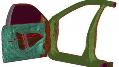
The geometric model of Car Door Assembly by using CATIA V5 and all Finite Element Setup by using ANSA, the entire assembly is meshed with shell elements, element size used between 2 to 10mm and maintained standard quality checks, meshed model is shown in Fig -4
Fig -4: Finite Element Model of Front Door Assembly
2.5 Model Setup for Different Load Cases
2.5.1 Sag Set: Load & Boundary Conditions
Fig -5: Sag Set model setup
1. Front Door sag set is carried out three steps of loading @ 25deg open positioned door:
Self weight of the door, followed by
Loading of 500N load at latch center applied in vertically downward direction
Unloading of door
2. Boundary Conditions:
Body-side cut section nodes constrained in all DOF
Latch node constrained in normal to door DOF for all steps to avoid rigid body motion in other direction. 3. Target : Sag <8mm and Permanent set should be Less than 1mm
2.5.2 Static Over Check: Load & Boundary Conditions
Fig -6: Static Over Check model setup
1. SOC is carried out three steps of loading @ 65deg open positioned door:
Self weight of the door, followed by
Follower load of 300N(65 deg door) load applied at latch center in normal to door
Unloading of door 2. Boundary Conditions:
For all 3 steps, constrained all nodes at cut section of the body
For first step in addition to above boundary condition; constrain latch node in direction normal to door and reset the same in second step.
3. Target : Permanent set should be Less than 5mm
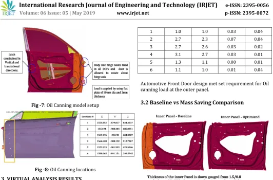
2.5.3 Oil Canning: Load & Boundary Conditions
This is to simulate the person leaning on door or to check the panel strength during the cleaning. 1. Boundary Conditions:
Hinge and Latch locations are constrained in all Degrees of freedom
[image:3.595.312.553.214.359.2] [image:3.595.70.266.310.421.2] [image:3.595.44.267.469.653.2]© 2019, IRJET | Impact Factor value: 7.211 | ISO 9001:2008 Certified Journal | Page 1789
Fig -7: Oil Canning model setup [image:4.595.34.567.46.396.2]Fig -8: Oil Canning locations
3. VIRTUAL ANALYSIS RESULTS
Table -4: Sag Set - Baseline vs Optimized
Automotive
Front Door Target, mm Baseline Door Optimized Door
Optimized Door Aluminum
Hinges Sag < 8.0 3.30 4.50 6.23
Set < 1 0.00 0.00 0.06
[image:4.595.28.293.437.521.2]Automotive Front Door design met Sag and Set performance requirements for 25deg open angle.
Table -5: Static Over Check - Baseline vs Optimized
Automotive
Front Door Target, mm Baseline Door Optimized Door
Optimized Door Aluminum
Hinges Set at Ajar
condition < 5.0 0.20 2.62 2.98
[image:4.595.312.551.558.709.2]Automotive Front Door design met set requirement for SOC load.
Table -6: Oil Canning - Baseline vs Optimized
Location #
Max Panel Deflection
<=10mm @ 200N Permanent Set <0.25mm Baseline Optimized Baseline Optimized
1 1.0 1.0 0.03 0.04
2 2.7 2.3 0.07 0.04
3 2.7 2.6 0.03 0.02
4 3.1 2.7 0.03 0.01
5 1.3 1.1 0.00 0.01
6 1.1 1.0 0.01 0.04
Automotive Front Door design met set requirement for Oil canning load at the outer panel.
3.2 Baseline vs Mass Saving Comparison
The car door results are generated for both baseline and optimized models from strength perspective. The oil canning, sag set and static over check results was showing comparable performance between baseline and optimized model. All the results was within the performance target with minimal degradation from the baseline model. The Aluminum hinge model along with single piece inner panel and hinge reinforcement with the optimized gauges was showing as best from the study. Following table shows the mass saving information.
[image:4.595.31.293.592.660.2]© 2019, IRJET | Impact Factor value: 7.211 | ISO 9001:2008 Certified Journal | Page 1790
Table -7: Mass Details - Baseline vs OptimizedParts Baseline (kg) per vehicle Optimized (kg) per vehicle
Mass saving per vehicle
(kg) Inner Panel 12.08 10.00
1.20 Tap Plate (Upper
& Lower) 0.32 0.20
Hinge
Reinforcement ** 1.00
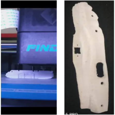
4. RAPID PROTOTYPE MODEL
Rapid proto-type model helps to understand the manufacturing feasibility and to have a feel of the part before actual tool development. A scaled hinge reinforcement part was developed using Fused Deposition Modeling(FDM) method and by using PLA material.
Fig -10: FDM of Hinge Reinforcement
4. CONCLUSION
The various types of car door architecture was studied in a detailed manner from various literatures. Swing car door structure and the related major strength load cases was identified for the optimization study. The robust design model idea was generated which consists of single piece inner panel and hinge reinforcement design. The earlier baseline design model was having the tailor welded blank inner panel without hinge reinforcement. The optimized gauge and material was identified by CAE simulation by using iteration methods. This study helped to conclude an optimized model with a massing saving of 1.2kg per vehicle. A scaled rapid proto-type model of hinge reinforcement using FDM method was generated finally.
REFERENCES
[1] Yan Qui, , “The New Technology in Automotive Industry by using Tailor Weld Blanks” International Welding Engineer Association.
[2] B C Patel, Jay Shah, Harindra Shah “Review of Formability of Tailor-Welded Blanks ISSN (Print): 2319-3182, Volume-1, Issue-1, 2012
[3] Kaushlendra Singh, Tom Strong, BadriVeera and PradeepMankuzhy, “Door Open Overload: Margin and Flushness Approach" SAE Technical Paper, 1999-01-3152.
[4] Peter Qio, Yuan Qu, Shenwu, "Finite Element Analysis of Door Closing Effort" SAE International, 2013-01-1398. [5] HR SAE J2340 300X HSLA steel material properties, www.asp.org/database/custom/hss_stampingDesignMa nu al.pdf, 24th June, 2009.
[6] AyanDutta, “Topology Optimization of the Inner Panel of an Automotive Door" ,IRJET, e-ISSN 2395-0056. [7] S Baskar, “Door Structural Durability”, SAE Technical
Paper, 2009-26-086, 2009.
[8] A paper entitled “Application of topology, sizing and shape optimization methods to optimal design
[9] Tamarin Y, "Atlas of stress-strain curves", ASM International, 2nd Edition, 2002.
[10] Billur, Eren & Altan T, "Challenges in Forming Advanced High Strength Steels", Internation conference on sheet metal forming, Sttutgart, 2010.
[11] Said Darwish, H. M. A. Hussein and Ahmad Gemeal "Numerical Study of Automotive Doors", International
Journal of Engineering & Technology IJET-IJENS Vol:12 [12] Amol S. Bhanage, Reshma Jawanjal, Sahil Bhamer,
[image:5.595.52.275.329.553.2]