Properties of Nanostructured TiCN and TiCN
TiAl Hard Materials
Sintered by the High-Frequency Induction-Heating
In-Jin Shon
1,+, Hyun-Su Kang
1, Song-Lee Du
2, Junyeon Hwang
2and Jae-Won Lim
31Division of Advanced Materials Engineering and the Research Center of Advanced Materials Development, Engineering College,
Chonbuk National University, Republic of Korea
2Carbon Convergence Materials Research Center, Korea Institute of Science and Technology, Jeonju, Republic of Korea
3Minerals and Materials Processing Division, Korea Institute of Geoscience, Mining and Materials Resources, Daejeon, Republic of Korea
In the case of cemented TiCN, Ni or Co is added as a binder for the formation of composite structures. However, the high cost of Ni or Co and the low corrosion resistance of the TiCNNi cermet have generated interest in recent years for alternative binder phases. In this study, TiAl was used as a binder and consolidated by the high-frequency induction heated sintering (HFIHS) method. Highly dense TiCNTiAl with a relative density of up to 100%was obtained within 2 min by HFIHS under a pressure of 80 MPa. The method was found to enable not only the rapid densification but also the inhibition of grain growth preserving the nano-scale microstructure. The average grain sizes of the sintered TiCN and TiCNTiAl were lower than 100 nm. The addition of TiAl to TiCN enhanced the hardness and toughness due to increase of relative density.
[doi:10.2320/matertrans.M2013200]
(Received May 27, 2013; Accepted July 29, 2013; Published September 13, 2013)
Keywords: nanomaterials, sintering, hardness, fracture toughness, hard materials
1. Introduction
TiCN is one of the promising ceramic materials, because it exhibits unusual combinations of physical and chemical properties such as high hardness, high melting point and excellent resistance to oxidation.1,2)Industrial applications of
the compound are in cutting tools and hard coatings. It is used extensively in cutting tool and abrasive materials in composite with a binder metal, such as Ni or Co. The binder phase has inferior chemical characteristics compared to the carbide or nitride phase. Most notably, corrosion and oxidation occur preferentially in the binder phase.3)Hence,
the high cost of Ni or Co and the low corrosion resistance of the TiCNNi cermet have generated interest in recent years to find alternative binder phases.4,5) It has been reported that aluminides show a higher oxidation resistance, a higher hardness and a cheaper materials compared to Ni or Co.6)
The improvement of mechanical properties and stability of cemented carbides could be achieved through microstructural changes such as grain size refinement.7,8) However, the use
of conventional methods to consolidate nanopowders often leads to grain growth due to the extended time for sintering. Generally, the grain growth could be minimized by sintering at lower temperatures and for shorter times. In this regard, the high-frequency induction heated sintering (HFIHS) technique has been shown to be effective in the sintering of nanostructured materials in a very short time (typically within 1 min).911)
We present here the results of the sintering of TiCN and TiCNNi composites by a high-frequency induction heated sintering with simultaneous application of induced current and high-pressure. The goal of this study was to produce dense and nanocrystalline TiCN and TiCNTiAl hard materials in very short sintering times (<2 min). The effect of novel TiAl binder on the mechanical properties and relative density of TiCN was examined.
2. Experimental Procedures
The TiCN powder used in this research was supplied by Treibacher Industrie AG (Germany). The average particle size was about 1.4 µm and the purity was 99%. The composition of C and N was 10.64 and 10.88 mass%, respectively. Oxygen was 0.24 mass%. TiAl (<45 µm, 99% pure, Ltschem Co.) was used as binder material. Powders of three compositions corresponding to TiCN, TiCN5 vol%TiAl and TiCN10 vol%TiAl were prepared by weigh-ing and milled in a high-energy ball mill (Pulverisette-5 planetary mill) at 250 rpm for 10 h. WC balls (9 mm in diameter) were used in a sealed cylindrical stainless steel vial under an argon atmosphere. The weight ratio of balls-to-powder was 30 : 1. The grain size of the powders was calculated from the full width at half-maximum (FWHM) of the diffraction peak by Suryanarayana and Grant Norton’s formula.12)
BrðBcrystallineþBstrainÞcosª¼k=Lþ©sinª ð1Þ
Where Br is the FWHM of the diffraction peak after
instrumental correction; Bcrystalline and Bstrain are FWHM
caused by small grain size and internal stress, respectively; k is constant (with a value of 0.9); is wavelength of the X-ray radiation; L and © are grain size and internal strain, respectively; and ª is the Bragg angle. The parameters B and Br follow Cauchy’s form with the relationship: B=
Br+Bs, where B and Bs are the FWHM of the broadened
Bragg peaks and the standard sample’s Bragg peaks, respectively.
A induced current was then activated and maintained until the densification rate became negligible, as indicated by the observed shrinkage of the sample. Sample shrinkage was measured in real time by a linear gauge measuring the vertical displacement. Temperature was measured by a pyrometer focused on the surface of the graphite die. A temperature gradient from the surface to the center of the sample is dependent on the heating rate, the electrical and thermal conductivities of the compact and its relative density. The heating rates were approximately 1200 °K min¹1 during the process. At the end of the process, the current was turned off and the sample was allowed to cool to room temperature. The entire process of densification using the HFIHS technique consists of four major control stages: chamber evacuation, pressure application, power application and
cooling off. The process was carried out under a vacuum of 5.33 Pa.
The relative densities of the sintered samples were measured by the Archimedes method. Microstructural information was obtained from the sintered compact using TEM. Compositional and microstructural analyses of the samples were carried out through X-ray diffraction (XRD), and field-emission scanning electron microscopy (FE-SEM). Vickers hardness was measured by performing indentations at a load of 10 kgf with a dwell time of 15 s.
3. Results and Discussion
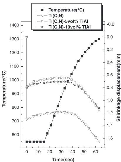
SEM images of TiCN, TiCN5 vol%TiAl and TiCN 10 vol%TiAl powders milled for 10 h are shown in Fig. 1. The powders are very fine and have a round shape. The shrinkage displacement-time (temperature) curve provides an important information on the consolidation behavior. Figure 2 shows the shrinkage record of TiCN, TiCN 5 vol%TiAl and TiCN10 vol%TiAl compacts under the applied pressure of 80 MPa. In all cases, there was a brief thermal expansion period as soon as the induced current was applied. After the initial expansion, the displacement rapidly increased. The application of the induced current resulted in shrinkage due to consolidation. The temperature of shrinkage initiation was seen to reduce by the addition of TiAl. It is considered that it is related to the melting of TiAl phase due to large Joule heat at contact of powders. Therefore, the main densification mechanism could be the rearrangement of carbide particles, enhancement of the diffusion and viscous flow of the binder.13)
(a)
(b)
(c)
Fig. 1 Scanning electron microscope images of powders milled for 10 h; (a) TiCN, (b) TiCN5 vol%TiAl and (c) TiCN10 vol%TiAl.
0 10 20 30 40 50 60 600
700 800 900 1000 1100 1200 1300 1400
Temperature(°C)
Ti(C,N)
Ti(C,N)-5vol% TiAl Ti(C,N)-10vol% TiAl
Time(sec)
T
e
mperature
(
°
C
)
1.6 1.4 1.2 1.0 0.8 0.6 0.4 0.2 0.0 -0.2
Shirinkage displacement(mm)
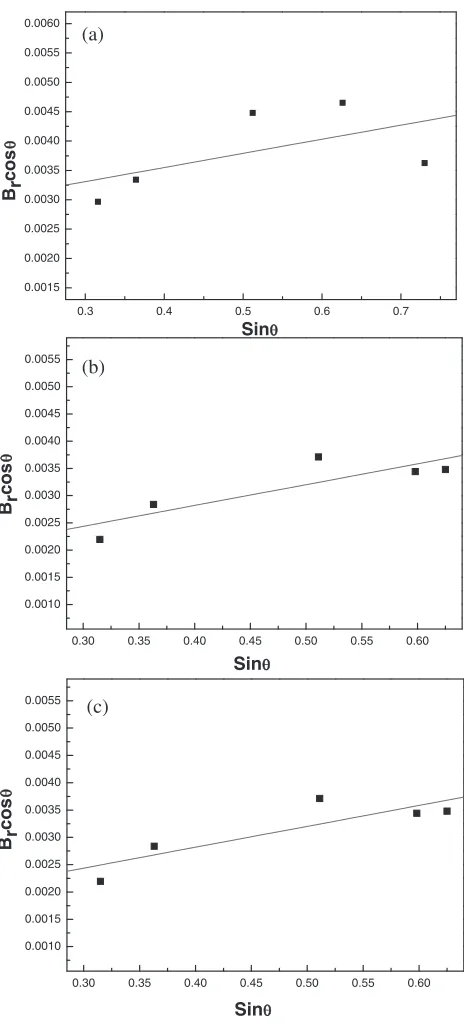
[image:2.595.323.529.66.342.2] [image:2.595.52.290.66.558.2]Figure 3 shows the XRD patterns of TiCN, TiCN 5 vol%TiAl and TiCN10 vol%TiAl after sintering. In all cases, only TiCN peaks are detected. Plot ofBr (Bcrystalline+
Bstrain) cosªversus sinªin Suryanarayana and Grant Norton’s
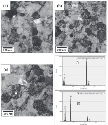
formula is shown in Fig. 4. The average grain sizes of the TiCN calculated from the XRD data are about 60, 55 and 95 nm for the samples with TiCN, TiCN5 vol%TiAl and TiCN10 vol%TiAl. TEM images of the samples after being sintered up to about 1300°C are shown in Fig. 5. It is apparent that the TiCN grains consist of nanocrystallites suggesting the absence of grain growth during sintering. This retention of thefine grain structure can be attributed to the high heating rate and the relatively short exposure to the high temperature. Relative densities corresponding to TiCN, TiCN5 vol%TiAl and TiCN10 vol%TiAl were
approxi-mately 94, 99 and 100%, respectively. EDX has been analyzed in TiCN10 vol%TiAl sample. TiCN existed at the area marked with O and TiAl at the area marked with X in Fig. 5(c).
The role of the current in sintering and/or synthesis has been the focus of several attempts to provide an explanation for the observed sintering enhancement and the improved characteristics of the products. The role played by the current has been variously interpreted. The effect has been explained by fast heating due to Joule heating at contacts points, the presence of plasma in pores separating powder particles and the intrinsic contribution of the current to mass transport.1417)
(c) (b)
(a)
All peaks are Ti(C,N)
0 100 200 300 400 500 600 0 100 200 300 400 500 600 700 800 900 Intensity
20 30 40 50 60 70 80
0 100 200 300 400 500 600 700 800 900 2 Theta
Fig. 3 XRD patterns of (a) TiCN, (b) TiCN5 vol%TiAl and (c) TiCN 10 vol%TiAl hard materials produced by HFIHS.
(a) (b) (c) 0.0015 0.0020 0.0025 0.0030 0.0035 0.0040 0.0045 0.0050 0.0055 0.0060 Brcos θ Sinθ 0.0010 0.0015 0.0020 0.0025 0.0030 0.0035 0.0040 0.0045 0.0050 0.0055 Sinθ Brcos θ
0.3 0.4 0.5 0.6 0.7
0.30 0.35 0.40 0.45 0.50 0.55 0.60
0.30 0.35 0.40 0.45 0.50 0.55 0.60 0.0010 0.0015 0.0020 0.0025 0.0030 0.0035 0.0040 0.0045 0.0050 0.0055 Sinθ Brcos θ
Fig. 4 Plot ofBr (Bcrystalline+Bstrain) cosªversus sinª for TiCN in (a)
[image:3.595.56.291.64.554.2] [image:3.595.312.544.66.579.2]Vickers hardness measurements were performed on polished sections of the TiCN, TiCN5 vol%TiAl and TiCN10 vol%TiAl samples using a 10 kg load and 15 s dwell time. Indentions with 10 kgf load produced median cracks around the indentation from which fracture toughness can be calculated. The lengths of these cracks permit estimation of the fracture toughness of the materials by means of the expression:18)
KIC¼0:203ðc=aÞ3=2Hva1=2 ð2Þ
Wherecis the trace length of the crack measured from the center of the indentation,ais one half of the average length of the two indent diagonals andHv is the hardness.
The Vickers hardness and the fracture toughness values of the TiCN, TiCN5 vol%TiAl and TiCN10 vol%TiAl sam-ples were 1521 kg/mm2, 3.9 MPa·m1/2 and 1847 kg/mm2,
5.5 MPa·m1/2and 2033 kg/mm2, 6.5 MPa·m1/2, respectively.
These values represent the average of five measurements. The hardness and fracture toughness of TiCN5 vol%TiAl and TiCN10 vol%TiAl samples are higher than those of
monolithic TiCN because the relative density of TiCN increases with addition of TiAl. The sintering method in this study was proven to be very effective to consolidate TiCNTiAl cermets. According to Ref. 19), relative density, hardness and fracture toughness of monolithic TiCN sintered at 1500°C using HFIHS were 99%, 1910 kg/mm2,
6.7 MPa·m1/2, respectively. The sintering temperature of
TiCN remarkably reduced with addition of TiAl. The hardness of metal carbide greatly decreased by addition of Co or Ni.20) The use of TiAl binder instead of Co or Ni is very effective especially to maintain the high hardness of monolithic TiCN without the expense of toughness reduction. In this regard, it would be worthwhile to consider TiAl as the possible replacement for Co or Ni especially for the applications requiring a high hardness.
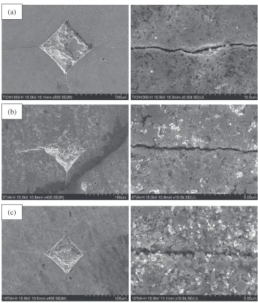
Vickers hardness indentations in the TiCN, TiCN 5 vol%TiAl and TiCN10 vol%TiAl samples are shown in Fig. 6. They show typically one to three additional cracks propagating radially from the indentation. The cracks propagated deflectively.
(a)
(b)
(c)
[image:4.595.113.486.68.498.2]4. Conclusions
Using high-frequency induction heated sintering (HFIHS), the rapid consolidation of the TiCN, TiCN5 vol%TiAl and TiCN10 vol%TiAl was accomplished successfully. Nearly full-dense TiCNTiAl composites could be obtained within 2 min. The densification temperature of TiCN was reduced remarkably by the addition of TiAl. The grain size of TiCN in TiCN, TiCN5 vol%TiAl and TiCN10 vol%TiAl hard materials were about 60, 55 and 95 nm, respectively. The hardness and fracture toughness values of TiCN, TiCN 5 vol%TiAl and TiCN10 vol%TiAl consolidated by HFIHS with a pressure of 80 MPa and a induced current were 1521 kg/mm2, 3.9 MPa·m1/2and 1847 kg/mm2, 5.5 MPa·m1/2and 2033 kg/mm2, 6.5 MPa·m1/2, respectively. The addition of
TiAl to TiCN improved the hardness and fracture toughness of cemented TiCN. It would be worthwhile to consider TiAl as the possible replacement for Co or Ni especially for the applications requiring a high hardness.
Acknowledgements
This study was supported by a grant from basic research project of Korea Institute of Geoscience and Mineral Resources, following results of a study on the “Leaders Industry-university Cooperation” Project, supported by the Ministry of Education, Science and Technology (MEST) and this research was supported by Basic Science Research Program through the National Research Foundation of Korea (NRF) funded by the Ministry of Education, Science and Technology (No. 2012001300).
REFERENCES
1) B. Gómez, A. Jiménez and E. Gordo:Int. J. Refract. Met. Hard Mater.
27(2009) 360366.
2) D. Mari, S. Bologini and T. Viatte:Int. J. Refract. Met. Hard Mater.19
(2001) 257265.
3) S. Imasato, K. Tokumoto, T. Kitada and S. Sakaguchi:Int. J. Refract. Met. Hard Mater.13(1995) 305312.
(a)
(b)
(c)
[image:5.595.109.486.66.508.2]4) G. Gille, J. Bredthauer, B. Gries and B. Mende:Int. J. Refract. Met. Hard Mater.18(2000) 87102.
5) P. Goeuriot and F. Thevenot:Ceram. Int.13(1987) 99103.
6) Z. G. Zhang, F. Gesmundo, P. Y. Hou and Y. Niu:Corros. Sci. 48
(2006) 741765.
7) H. Gleiter:Prog. Mater. Sci.33(1989) 223315.
8) G. E. Fougere, J. R. Weertman, R. W. Siegel and S. Kim:Scr. Metall. Mater.26(1992) 18791883.
9) N.-R. Park and I.-J. Shon:Mater. Trans.54(2013) 10491052.
10) I. J. Shon, I. Y. Ko, H. S. Kang, K. T. Hong, J. M. Doh and J. K. Yoon:
Met. Mater. Int.18(2012) 115119.
11) I. Y. Ko, N. R. Park and I. J. Shon: Korean J. Met. Mater.50(2012) 369374.
12) C. Suryanarayana and M. Grant Norton:X-Ray Diffraction: A Practical
Approach, (Plenum Press, New York, 1998).
13) G. S. Upadhyaya:Mater. Des.22(2001) 483489.
14) Z. Shen, M. Johnsson, Z. Zhao and M. Nygren:J. Am. Ceram. Soc.85
(2002) 19211927.
15) J. E. Garay, U. Anselmi-Tamburini, Z. A. Munir, S. C. Glade and P. Asoka-Kumar:Appl. Phys. Lett.85(2004) 573575.
16) J. R. Friedman, J. E. Garay, U. Anselmi-Tamburini and Z. A. Munir:
Intermetallics12(2004) 589597.
17) J. E. Garay, U. Anselmi-Tamburini and Z. A. Munir:Acta Mater.51
(2003) 44874495.
18) K. Niihara, R. Morena and D. P. H. Hasselman:J. Mater. Sci. Lett.1
(1982) 1316.
19) W. Kim, C.-Y. Suh, K.-M. Roh, J.-W. Lim, S. Lee, S.-L. Du and I.-J. Shon:Ceram. Int.39(2013) 585591.
20) I.-J. Shon, I.-K. Jeong, I.-Y. Ko, J.-M. Doh and K.-D. Woo:Ceram. Int.
![Crystal structure of N [4 amino 5 cyano 6 (methylsulfanyl)pyridin 2 yl] 2 (cyclohexylsulfanyl)acetamide](data:image/gif;base64,R0lGODlhAQABAIAAAP///wAAACH5BAEAAAAALAAAAAABAAEAAAICRAEAOw==)