Optimization of Welding Condition for Nonlinear Friction Stir Welding
*1Hironori Takahara
1;*2, Masato Tsujikawa
1, Sung Wook Chung
2;*3,
Yuzo Okawa
3, Kenji Higashi
1and Sachio Oki
41
Department of Materials Science, Graduate School of Engineering, Osaka Prefecture University, Sakai 599-8531, Japan 2Division of Technology Licensing Organization Osaka Prefecture, Osaka 541-0053, Japan
3Technical Research Institute of Osaka Prefecture, Izumi 594-1157, Japan
4Department of Mechanical Engineering, School of Science and Engineering, Kinki University, Higashiosaka 577-8502, Japan
The influence of nonlinear friction stir welding (FSW) tool control on joint properties was investigated. Although FSW is widely applied to linear joints, it is impossible for five-axis FSW machines to maintain all FSW parameters in optimum conditions during nonlinear welding. Nonlinear FSW joints should be produced according to an order of priority for FSW parameters. Tensile test results of butt joints with rectangular change in the welding direction on the plate plane (L-shape butt joints) change with various welding parameters. Results show that a turn to the retreating side is encouraged when the welding direction changes. The method of zero inclination tool angles is effective for nonlinear and plane welding. [doi:10.2320/matertrans.L-MRA2008807]
(Received January 4, 2008; Accepted February 28, 2008; Published April 16, 2008)
Keywords: friction stir welding, nonlinear welding, aluminum alloy, microstructure, mechanical properties
1. Introduction
Friction Stir Welding (FSW) is a new joining process, which used frictional heat generated between rotational tool and material. FSW is a solid-state welding. Therefore, it has excellent properties such as low distortion and low residual stress. FSW is widely applied to linear joints.1)When FSW becomes to be capable to nonlinear joints, it can be applied to many industries.2,3) However, there are two problems that nonlinear FSW can’t be applied easily as below. (1) Occurrence of deviation from appropriate welding parameter made by complicated tool control. (2) Presence of unsteady welding condition area made by FSW parameter change. Such two problems are described as below.
(1) At nonlinear welding, it is necessary to change the tool position or tool attitude continuously along the butt line. For example, in the practical welding, it is more difficult to set the tool center at butt line accurately during entire welding at nonlinear welding than linear welding. Because many kinds of mechanical errors accumulate on the deviation between tool center and butt line. Similarly, the deviation of tool inclination is anticipated. It is important for applying nonlinear FSW to improve operational accuracy. On the other hand, it is also important to clarify the tolerance of opera-tional deviation. Our group investigated the influence of such deviations on mechanical properties of butt joints by tensile tests, and clarified tolerance of such deviations.4–6)
(2) There are some places where the welding parameters change at nonlinear FSW. The change in welding parameters made welding unsteady as shown in Table 1. Furthermore, it is difficult to keep all welding parameters in appropriate permissible ranges at the places because of the limitation of the degree of freedom. The deviations of some parameters make the welding condition worse. That is, in the place of
welding parameter change, the welding conditions get unsteady and the deviations of welding condition from proper values could occur. We should select the parameter with priority, because some parameters have greater influ-ence on joint properties than other. The objective of this work is to clarify the influence of welding parameter change on joint properties. Nonlinear joints were made by keeping the selected parameter in permissible range. Tensile tests were carried out by specimens prepared from the joints. The effects of un-selected parameter on the tensile properties were clarified by the selection of the parameter with priority. These results will show the guidelines for high quality joints at nonlinear welding.
2. Experimental Procedure
2.1 FSW machine and welding condition
Three-dimensional FSW machine used in this experiment is shown in Fig. 1. The machine has five-degree-of-freedom, X-Y-Z driving axis and A-C rotational axis. Material used was 5083-O aluminum alloy plate of 3 mm in thickness. The tool used was made of JIS SKD61 tool steel. It has 12 mm diameter shoulder, 3 mm diameter and 2.85 mm length probe. Tool rotational speed is 800 rpm, tool-traveling speed is100200mm/min, and tool rotational direction is clockwise rotation viewed from above. It has been clarified that good joints can be made by this welding condition.4–6)
2.2 Tolerance of operational deviations
It has possibility some operational deviations occur during FSW. (1) Butt-line/tool-travel-line deviation: the deviation between butt line and tool travel line. (2) Gap space: the gap space at butt-face. (3) Pitching angle of the tool: the deviation of tool inclination angles for welding direction. (4) Rolling angle of the tool: the deviation of tool inclination angle for transversal direction. These deviations occur frequently at two or three-dimensional welding than linear welding. In this research, the tolerance of deviation at linear welding was clarified, firstly. (1) These pair of plate was horizontally set *1This Paper was Originally Published in Japanese in Journal of Japan
Institute of Light Metals57(2007) 542–548. *2Graduate Student, Osaka Prefecture University
*3Present address: Daewoo Shipbuilding & Marine Engineering Co., Ltd.,
656-714 Korea
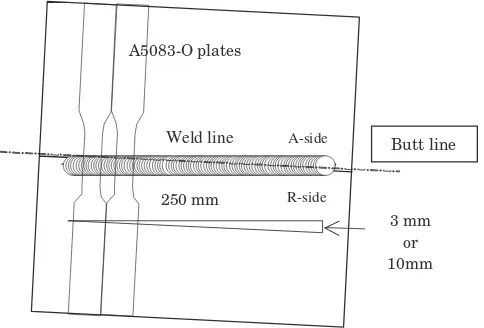
on the FSW machine with specific angle between butt line and tool travel line. As a result of the setting, the joints had continuous deviation of the butt line from the center of friction stir line as shown in Fig. 2. (2) The illustration of the butt joint with gap space at butt face is shown in Fig. 3. The material was processed to make gap beforehand by machin-ing process. The gap space width was changed from 0.2 to 3.0 mm. Probe center passed to center of gap space during
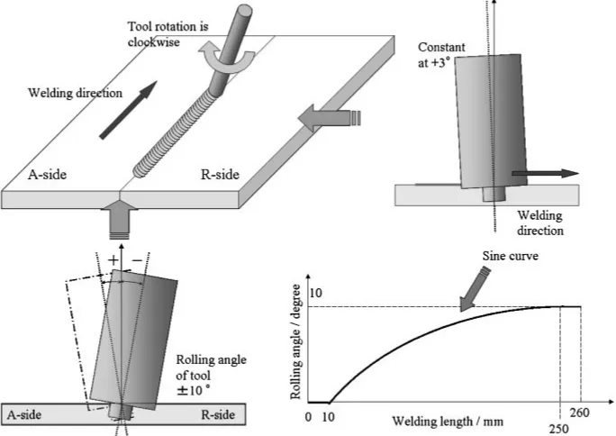
welding. (3) The experiment about pitching angle of the tool is shown in Fig. 4. Tool inclination angle for welding direction was changed from 1:0to 5.0 degrees continuously during welding. The coordinates of the tool tip changed as tool inclination angle change. Because the coordinates of the tool tip need to be corrected. In addition, tool tip indicates the point of probe center and root part. (4) Schematic illustration
(Y)
(C) (Z)
(A) (b)
(a) (c)
[image:2.595.49.538.78.428.2]Fig. 1 Five axis controlled FSW machine for three-dimensional welding, (a) feature of FSW machine, (b) three-dimensional head, (c) illustration of five degrees of freedom.
Table 1 Example of unsteady conditions in nonlinear FSW.
Welding parameter change
Example of unsteady areas Welding Pitching angle Rolling angle Probe insertion
speed of the tool of the tool depth
Tool head swing
Change of the tool traveling direction
Change of the work shape for
pitching angle —
Change of the work shape for rolling angle
Change of the work thickness
Welding start or end point — — —
Uneven surface of work
3 mm or 10mm 250 mm
A5083-O plates
Butt line
Weld line A-side
R-side
Fig. 2 Preparation of butt-line/tool-travel-line deviation tensile speci-mens.
Butt line
Welding direction Gap space width 0.2
Gap space length 60 mm Tool rotational direction
A-side
R-side
3.0 mm
Fig. 3 Welding with various gap space at butt surface.
(a) (b)
Welding direction
[image:2.595.45.549.85.252.2] [image:2.595.49.291.475.639.2] [image:2.595.305.547.479.664.2] [image:2.595.307.546.577.661.2]of rolling angle of the tool is shown in Fig. 5. Tool inclination angle for welding direction was constant at 3 degrees during FSW, and rolling angle of the tool continuously changed from 0 degrees to plus/minus 10 degrees. Rolling angle of the tool were controlled in sinusoidally changed with constant insertion depth of probe as shown in Fig. 5. The rolling angle of the tool to the advancing side (hereinafter called the A-side) was defined as positive roll, vice versa.
2.3 Nonlinear FSW butt joints (L-shape butt joints)
Butt joints with rectangular change in welding direction on plate plane (L-shape butt joints) are made as a nonlinear joint. Two kinds of joints, which turn to the A-side or turn to the retreating-side (hereinafter called the R-side), are made. The feature of L-shape butt joints which turn to the R-side is shown in Fig. 6.
Three different tool control method were used to make the joints as listed in Table 2. (a)In-situtool head swing: Tool head swing is needed to keep tool attitude appropriate. Correction of X-Y coordination needed when tool head swing. It takes time for tool head swing. Therefore, the welding speed is the unselected parameter. It is not in per-missible range. (b) Zero inclination tool angles: Butt joints are welded with zero inclination tool angles. It can keep welding speed stable, because tool attitude change and tool head swing is not necessary. The tool inclination angles is the unselected parameter. (c) Shortcut of the tool pass: Shortcut means that the tool traveling pass cuts corners as in Fig. 7.
The tool inclination angles and welding speed are constant, but the tool position deviates from the center of butt line.7,8)
3. Results and Discussion
3.1 Tolerance of operational deviations
The influence of butt-line/tool-travel-line deviation on the tensile strength is shown in Fig. 8. The tensile strength Fig. 5 Welding with various inclination tool angles (rolling angle of the tool).
[image:3.595.127.469.75.317.2]Fig. 6 Two-dimensional FSW butt joint with rectangular change in welding direction (L-shape butt joints which turn to the R-side).
Table 2 List of welding parameters for three different methods of tool control.
Welding Modified
parameter
Parameters kept as optimum condition evaluated in linear welding
(a)In-situtool head swing Welding speed Tool angle, Tool traveling pass
(b) Zero inclination tool angles Tool angle Welding speed, Tool traveling pass
[image:3.595.306.548.364.542.2] [image:3.595.47.549.721.786.2]is stable at the deviation range from 1:5mm to center, 0.0 mm. Outside of this range, the strength is rapidly decreased. Judging from Fig. 8, there is no tolerance in the R-side. The butt line must be at the A-side to obtain the good joints. The center of good joints region is with the deviation of 0:75mm. This value is the half of the tool probe diameter. Therefore, the maximum tolerance for tool center and butt line deviation is made by the setting of butt line is in the A-side and the deviation should be the half of the tool probe diameter.
The influence of gap space on tensile strength is shown in Fig. 9. Tensile strength of specimens with gap space by 1.5 mm is almost equal to that of base metal. The decrease of strength was gradual with increase in gap space by 2.5 mm. Such tendency of gap space effect is different from that of butt-line/tool-travel-line deviation in which the strength decreased rapidly beyond the critical deviation value of
1.5 mm for the A-side or 0 mm for the R-side. The rupture of joints occurred at the base metal for the specimen prepared with gap space within 1.5 mm.
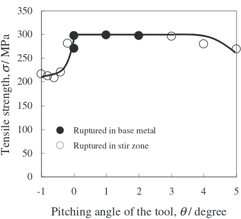
The influence of pitching angle of the tool on tensile strength is shown in Fig. 10. Pitching angle of the tool is inside of 03 degrees, specimens have sufficient tensile strength and ruptured in base metal. As increase pitching angle of the tool from 3 degrees, tensile strength decrease gradually. The pitching angle of the tool is minus range, tensile strength decrease rapidly.
The influence of rolling angle of the tool on tensile strength is shown in Fig. 11. Rolling angle of the tool is inside of plus/minus 2 degrees, specimens have sufficient tensile strength and ruptured in base metal. The decrease of strength was gradual with increase in rolling angle of the tool.
Fig. 7 The feature of the joints with the shortcut of the tool pass.
0 50 100 150 200 250 300 350
-4
Butt-line/tool-travel-line deviation,
d
/ mm
Tensile strength,
σ
/ MPa
Ruptured in base metal
Ruptured in stir zone
4 3 2 1 0 -2
-3 -1
Fig. 8 Influence of butt-line/tool-travel-line deviation on tensile proper-ties.
0 50 100 150 200 250 300 350
0
Gap space,
d
/ mm
Tensile strength,
σ
/ MPa
Ruptured in base metal
Ruptured in stir zone
3 2.5 2
1.5 1
0.5
Fig. 9 Influence of gap space on tensile properties.
0 50 100 150 200 250 300 350
-1
Pitching angle of the tool,
θ
/ degree
Tensile strength,
σ
/ MPa
Ruptured in base metal
Ruptured in stir zone
[image:4.595.84.254.72.229.2]5 4 3 2 1 0
[image:4.595.309.547.73.285.2] [image:4.595.52.291.283.524.2] [image:4.595.309.547.335.551.2]3.2 Nonlinear FSW butt joints (L-shape butt joints)
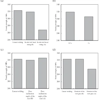
Results of tensile test by the specimens welded within-situ tool head swing is shown in Fig. 12(a). The bar in the left named ‘‘Linear welding’’ is the strength of reference joint made in linear welding of FSW. The bar at the center indicates the average strength of three specimens from the
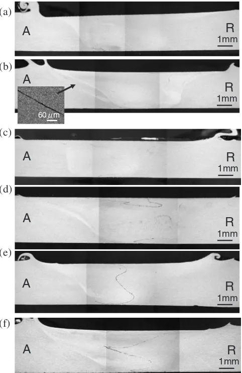
joints welded within-situtool head swing, turn to the R-side. The bar in the right also shows those of turn to the A-side. The strength of the R-side turn joints is good as well as linear welding joints, and these joints ruptured in base metal. In contrary the strength of the A-side turn joints decreased, and these joints ruptured in stir zone. It is thought that strength reduction is caused by some clear Lazy-S9,10) shown in Fig. 13(b). In this tool control method, the time during tool head swing is important factor. The influence of the time on tensile strength is investigated. The result of tensile test is shown in Fig. 12(b). The left bar shows the strength of the joints which the time of tool head swing is 0.5 s. The right bar also shows the strength those of 3 s. Strength reduction is shown at the specimen of 3 s, and the specimens of 3 s ruptured in stir zone.
Results of tensile test by specimens welded with zero inclination tool angles are shown Fig. 12(c). Specimens of turn to the R-side and the A-side have enough tensile strength as specimen of linear welding. The all positions of rupture were at base metal. Some complicated or choppy Lazy-S is recognized at cross section view of specimen turn to the A-side shown in Fig. 13(d). The results indicate that the method welded with zero inclination tool angles is an effective process. It has been clarified that negative inclina-tion tool angles causes drastic reducinclina-tion of strength.4–6)The zero inclination tool angles method is ideal for linear or two-dimensional plane welding, but it is difficult to keep the angle
0 50 100 150 200 250 300 350
-10
Rolling angle of the tool,
θ
/ degree
Tensile strength,
σ
/ MPa
Ruptured in base metal
Ruptured in stir zone
[image:5.595.51.291.75.284.2]10 8 6 4 2 0 -2 -4 -6 -8
Fig. 11 Influence of the rolling angle of the tool on tensile properties.
240 260 280 300 320 340
Linear welding In-situ tool head swing (R)
In-situ tool head swing (A)
Tensile strength,
σ
/ MPa
240 260 280 300 320 340
Linear welding Zero inclination angle of the
tool (R)
Zero inclination angle of the tool (A)
Tensile strength,
σ
/ MPa
240 260 280 300 320 340
Linear welding Shortcut of the tool pass (R)
Shortcut of the tool pass (A)
Tensile strength,
σ
/ MPa
240 260 280 300 320 340
0.5 s 3 s
Tensile strength,
σ
/ MPa
(d) (a)
(c)
[image:5.595.125.470.410.758.2](b)
at zero in dimensional welding. In practice of three-dimensional welding, positive inclination tool angle is needed for tolerance.
Result of tensile test by specimens welded with shortcut of the tool pass is shown in Fig. 12(d). Joints of turn to the R-side have enough tensile strength as that of linear welding. Strength reduction is shown at specimen of turn to the A-side. Clear Lazy-S is shown both turn to the R-side and turn to the A-side in Fig. 13(e) and (f). It is discouraged from welding with shortcut of the tool pass, because the enough stirring can not be obtained and butt line remains as clear Lazy-S. It is clarified that the R-side deviations of butt line from tool center have no tolerance in our study.7,8) The strength deteriorates only in the case of turn to the A-side.
All specimens turn to the A-side have clear Lazy-S. It can be explained as below. Tool rotational direction is clockwise in this study. When tool head turn to the A-side, tool traveling direction is mismatch tool rotational direction. This mis-match makes negative effect on material flow and fracturing Lazy-S.11–13)It is encouraged to turn to same direction as tool rotational direction when welding direction change. The strength deteriorates at the specimen with continuous Lazy-S
as Fig. 13(b). On the other hand, the enough strength kept in linear welding at the specimen with complicated or choppy Lazy-S as Fig. 13(d).
4. Conclusions
The results of experiments tolerance of deviation at nonlinear welding is made into a Table 3. And it is clarified about nonlinear welding as below.
(1) It is encouraged to turn to same direction as tool rotational direction when welding direction change. (2) When it can not avoid the tool head swing, it is
important to swing speedy and smooth, with that ward off stay on-site of tool.
(3) The method of zero inclination tool angles is effective at nonlinear and plane welding.
(4) It needs that to have inclination tool angles for having tolerance at three-dimensional welding.
Acknowledgment
This research has been supported by Osaka East Urban Area Industry-Government-Academia Collaboration Project on FSW ‘‘CITY AREA’’ sponsored by MEXT, conducted by Osaka TLO 2004–2007.
REFERENCES
1) T. Kawasaki, T. Makino, K. Masai, H. Ohba, Y. Ina and M. Ezumi: JSME International Journal Series A.47(2004) 502–511.
2) S. Hirano: Journal of Light Metal Welding & Construction.43(2005) 565–569.
3) H. Takehisa: Journal of Japan Institute of Light Metals. 56(2006) 178–183.
4) M. Tsujikawa, H. Takahara, S. Oki, S. W. Chung, T. Hirata and K. Higashi: Collected Abstracts of the Japan Institute of Light Metals. 109(2005) 321.
5) T. Hirata, T. Oguri, H. Hagino, S. W. Chung, M. Tsujikawa and K. Higashi: Proc. International Symposium on Joining Technologies in Advanced Automobile Assembly 2005, (JAAA2005, Tokyo, Japan, Octber 2005) pp. 195–202.
6) T. Hirata, T. Oguri, H. Hagino, T. Tanaka, S. W. Chung, M. Tsujikawa, Y. Takigawa and K. Higashi: Key Engineering Materials 340–341 (2007) 1473–1478.
7) S. Oki, M. Tsujikawa, Y. Okawa, H. Takahara, S. W. Chung and K. Higashi: 6th International Symposium on Friction Stir Welding, (Saint-Sauveur, Nr Montreal, Canada, October 2006) paper No. 45. 8) H. Takahara, Y. Motoyama, M. Tsujikawa, S. Oki, S. W. Chung and
K. Higashi: Advanced Material Research15–17(2007) 375–380. 9) A. Oosterkamp, L. D. Oosterkamp and A. Nordeide: Welding Journal
83-8(2004) 225–231.
10) Japan Welding Society:Friction Stir Welding, (2006) pp. 61–62. 11) H. Okamura, K. Aota, M. Sakamoto, M. Ezumi and K. Ikeuchi:
Quarterly Journal of the Japan Welding Society19(2001) 446–456. 12) K. Colligan: Welding Journal (1999) 229–237.
13) H. N. B. Schmidt, T. L. Dickerson and J. H. Hattel: Acta Materialia 54(2006) 1199–1209.
A
A
(a)
(d)
(e)
(b)
A
A
(c)
(f)
R
1mm
R
1mm
R
1mm
R
1mm
R
1mm
R
1mm
A
A
[image:6.595.49.290.72.443.2]60 mµ
Fig. 13 Cross-section view of joint at unsteady area, (a)in-situtool head swing, turn to the R-side, (b)in-situtool head swing, turn to the A-side, (c) zero inclination angle of the tool, turn to the R-side, (d) zero inclination angle of the tool, turn to the A-side, (e) shortcut of the tool pass, turn to the R-side, (f) shortcut of the tool pass, turn to the A-side.
Table 3 Allowance range of operational deviation.
Butt-line/tool-travel-line deviation 1:50mm
Gap space 1:5mm
Pitching angle of the tool 03degree
[image:6.595.306.550.85.142.2]