© 2016, IRJET | Impact Factor value: 4.45 | ISO 9001:2008 Certified Journal
| Page 26
Design and Experimental study of Friction stir welding of AA6061-T6
Alloy for optimization of welding parameters by using Lathe Machine
Piyush Patel
1, Sachin Patel
2, Hiren Shah
31,2,3
Assistant Professor, Mechanical Engineering Department, C G Patel Institute of Technology, Uka Tarsadia
University, Bardoli, Surat, India
---***---Abstract -
Friction stir welding is a new solid statewelding process for joining metallic alloys and it is useful in serve industries for joining aluminium, magnesium and copper alloys. The various parameter such as rotational speed, transverse speed and tool tilt angle play important roles in FSW process and quality weld. The aim of this study is to know the relation between the effects of different transvers speed and tool profile on the weld quality of AA6061-T6 aluminium. The geometry of the pin tool along with the process parameters plays an important role in dictating the path that the material takes. The tool geometry was carefully chosen and fabricated to have a nearly flat welded interface pin profile. In this work, an attempt has been made to analyze the effect of various tool profiles on mechanical properties of aluminium alloy. Various tool profiles have been used to fabricate joints by using varying thickness work piece of Aluminium alloy. Numerical techniques particularly, the finite element method for the simulation of FSW for thermal, mechanical and thermo-mechanical modelling has been investigated. The current studies also
aim to understand mechanical properties during the FSW.
Key Words: Friction Stir Welding, Transient Thermal
Analysis, Al6061, Process parameter, Tool Profile
1.INTRODUCTION
Friction Stir Welding process is relatively a new joining process that is presently attracting considerable interest. Since the joint can be obtained below the melting temperature, this method is suitable for joining a number of materials those are extremely difficult to be welded by conventional fusion techniques. The process is solid state in nature and relies on the localized forging of the weld zone to produce the joint.
A constantly rotated non consumable cylindrical tool with a profiled probe is transversely fed at a constant rate into a butt joint between two clamped pieces of butted material. The probe is slightly shorter than the weld depth required, with the tool shoulder riding a top the work surface.
Frictional heat is generated between the wear resistant welding components and the work pieces. This heat, along with that generated by the mechanical mixing process and the adiabatic heat within the material, cause the stirred materials to soften without melting.
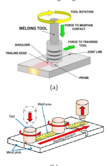
[image:1.595.342.524.459.741.2]FSW is actually performed in different steps as shown in figure 1. The probe primary function is to mix the material under the tool shoulder, which can be enhanced by threads. First, the probe is plunged into the joint formed by the two sheets to be welded, until the shoulder gets in contact. As the tool rotates at a high velocity, the sheets are heated up by plastic deformation and friction. As the pin is moved forward, a special profile on its leading face forces plasticized material to the rear where clamping force assists in a forged consolidation of the weld. This process of the tool traversing along the weld line in a plasticized tubular shaft of metal results in severe solid state deformation involving dynamic recrystallization of the base material. Figure 1 shows process of tool traversing along the weld line. [1], [2]
(a)
© 2016, IRJET | Impact Factor value: 4.45 | ISO 9001:2008 Certified Journal
| Page 27
(c)
Fig -1: Schematic representation of FSW process
1.1 Key of Benefits
[image:2.595.79.250.95.257.2]In contrast to the traditional friction welding, which is usually performed on small axisymmetric parts that can be rotated and pushed against each other to form a joint, FSW can be applied to various types of joints like butt joints, lap joints, T butt joints and fillet joints.
Table -1: The key benefits of FSW Process
Metallurgical benefits
Environmental Benefits
Energy benefits
Solid phase process No shielding gas required
Reduction in weight
Good dimensional stability and repeatability
Eliminate grinding waste Decrease fuel consumption
No loss of Alloying elements
Eliminate solvents required for degreasing
Excellent metallurgical properties in the joint area
Consumable materials saving such as rugs , wire or any other gases
1.2 Comparison of friction stir welding to other
welding processes
Comparison of FSW to other welding processes is typically done within the context of justifying the use of the process over other, more conventional techniques. Successful application of FSW depends upon a clear misunderstanding of the characteristics of the process, so favorable technical and economic justification can be developed.
The unique, favorable characteristics of FSW compared to traditional arc welding methods provide several sources for technical justification for use of the process. [3], [4]
The main points for technical justification of FSW compared to arc welding processes are;
Improved weld ability Reduced distortion Reduced residual stress
Improved cosmetic performance
Elimination of under matched filler metal Improved static strength and ductility Mechanized process
High robustness and few process variables
2. DESIGN APPROACH
Generally, Friction stir welding is performed on the Milling or Radial cum drilling machine. But our main objective is to perform operation onto Lathe Machine. So for that an attachment is required to hold a welding plate on a lathe machine. [9], [10]
2.1 Basic Requirement of machine:
The performance test on Lathe machine for the FSW Technique is analyzed for the different parameters.
[image:2.595.310.513.351.477.2]2.1.1 Light duty lathe machine specification:
Fig- 2: Lathe Machine
Table-2: Light duty lathe machine specification
Sr no Features Values
1 Swing over bed 90 mm
2 Swing over carriage 45 mm
3 Distance between center 430 mm
4 Overall length 820 mm
5 Overall width 220 mm
6 Overall height 200 mm
7 Shipping weight 140 kg
8 Hole through spindle 10 mm
[image:2.595.53.271.402.560.2]© 2016, IRJET | Impact Factor value: 4.45 | ISO 9001:2008 Certified Journal
| Page 28
2.1.2 Lathe attachment
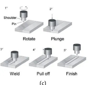
[image:3.595.330.534.123.364.2]Now for holding a welding plate on lathe machine an additional attachment is required for mounting purpose. Figure 3 show CAD Geometrical view of lathe attachment for holding of welding plate.
Fig-3: CAD Geometrical view of Lathe Attachment (All dimensions are in mm)
2.2 Basic requirement of tool geometry
A novel pin is design for friction stir welding tools that can penetrate more apply into work pieces to form a thicker weld joint without overloading the tool. The pin is providing with cylindrical and taper face on surface of tool. The diameter of the tool shoulder to the diameter of the tool pin (Ds/Dp) are chosen based on the literature survey. The shoulder of tool is designed to produce heat on the surface of the work pieces. The tool shoulder accounts for majority of the deformation and frictional heat generation between the work pieces. Due to large surface area, friction increases, which in turn increases the amount of heat generated.[6], [7], [8]
[image:3.595.45.245.179.312.2]Fig-4. Tool Geometry
TABLE 3. Tool design parameter [15]
Weld tool Geometry AL TI Steel (HMTM)
DS/DP 2.4 1.2-3.8 2.3-2.4
DP/LP 1.5 1.4-1.9 1.7-2.0
Pin surface Treads Smooth Smooth
Taper 0 30-60 30-60
2.2.1 Types of tool
Taper tool:
Fig- 5: CAD geometry of Taper Tool (All dimensions are in mm)
Cylindrical tool:
Fig- 6: CAD geometry of Cylindrical tool (All dimensions are in mm)
2.2.2 Base plate
[image:3.595.365.540.429.648.2]© 2016, IRJET | Impact Factor value: 4.45 | ISO 9001:2008 Certified Journal
| Page 29
Fig- 7: CAD Geometrical Dimension (All dimensions are in mm)
3. SIMULATION BASED APPROACH
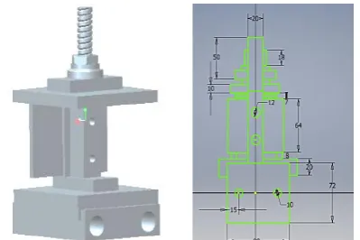
[image:4.595.326.540.212.367.2]Three-dimensional thermo mechanical model and the thermo mechanical effect of the welded material is developed for the FSW of an Al-alloy, in order to build qualitative framework to understand the thermo mechanical process in FSW. In this analysis work below figure shows the total deformation and temperature graph for a cylindrical tool geometry. The prediction and the measurement show that the maximum temperature gradients in longitudinal and lateral directions are located just beyond the shoulder edge. To simulate this kind of welding process, a fully coupled thermo-mechanical solution has been adopted to simulate the FSW process. [11], [13]
Fig- 8: Total deformation and Temperature profile
Figure 8 show the Total deformation and temperature profiles in the work piece during the welding operation for N2=900 rpm; T2 = 3.16 mm/min and for a cylindrical tool
profile for the size of 4 mm thickness plate.[14], [16]
4. EXPERIMENTAL WORK
Experimental setup was recognized using a light duty lathe machine. No extra setup is required for friction stir welding except tool and fixture, so as to place piece in proper position during welding. The different process parameters
are discussed below which are effecting for the Analysis on FSW. [15]
4.1 Process parameter
[image:4.595.46.240.385.591.2]The various process parameters play important roles in FSW process and quality weld.
Table 4: Main FSW process variables
Tool design variables Machine variables Other variables
Shoulder and pin
material Welding speed Anvil material
Shoulder diameter Spindle speed Anvil size
Pin diameter Plunge force or depth Work piece size
Pin length
Tool tilt angle Work piece properties Thread pitch
Feature geometry
There are so many parameters are effecting for the analysis on friction stir welding as shown in Table 4. As many parameters are important in the friction stir welding but in this experiment main two parameters are selected for analysis by using lathe machine;
(1) Tool speed (2) Transvers speed
The proper choice of tool rotation and transverse speed will produce a good quality weld. The material use for base plate is Al alloy 6061 and the material use for the tool geometry is EN8.
4.2 Process step for friction stir welding on lathe
machine
[image:4.595.316.558.628.776.2]© 2016, IRJET | Impact Factor value: 4.45 | ISO 9001:2008 Certified Journal
| Page 30
Fig-9: Process steps for FSW Experiment
In the present work, different FSW butt welds were obtained by varying the process parameters within the range and the optimal values are drawn based on the trend of the values. In this experiment it is observed that the process parameters like tool design, tool rotational speed, welding speed and materials are the main parameters to produce the effective butt joint by friction stir welding. [17]
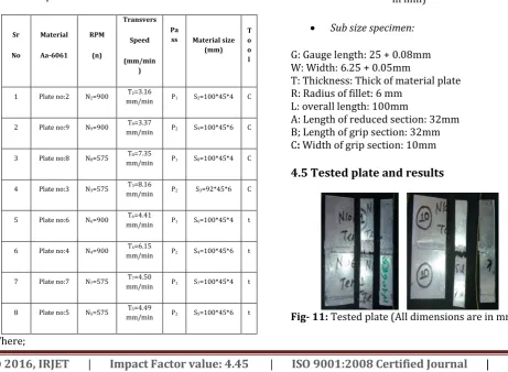
[image:5.595.57.267.111.291.2]4.3 Observation table
Table 5: Experiment data
Sr
No
Material
Aa-6061 RPM
(n)
Transvers
Speed
(mm/min )
Pa
ss Material size (mm)
T o o l
1 Plate no:2 N2=900 mm/min T2=3.16 P1 S2=100*45*4 C
2 Plate no:9 N9=900 mm/min T9=3.37 P2 S9=100*45*6 C
3 Plate no:8 N8=575 mm/min T8=7.35 P1 S8=100*45*4 C
4 Plate no:3 N3=575 mm/min T3=8.16 P2 S3=92*45*6 C
5 Plate no:6 N6=900 mm/min T6=4.41 P1 S6=100*45*4 t
6 Plate no:4 N4=900 mm/min T4=6.15 P2 S4=100*45*6 t
7 Plate no:7 N7=575 mm/min T7=4.50 P1 S7=100*45*4 t
8 Plate no:5 N5=575 mm/min T5=4.49 P2 S5=100*45*6 t
Where;
Plate no 2: (P1N2T2S2C); Cylindrical Tool = C; Tapper Tool = t; RPM = N; Transvers speed = T; Material size = S; Single pass = P1; Double pass = P2
4.4 Tensile Tests: -
Tensile strength, along with elastic modulus and corrosion resistance, is an important parameter of engineering materials used in structures and mechanical devices.
[image:5.595.324.507.225.424.2] Tensile test specimen geometry
Fig-10: Tensile test specimen (All dimensions are in mm)
Sub size specimen:
G: Gauge length: 25 + 0.08mm W: Width: 6.25 + 0.05mm
T: Thickness: Thick of material plate R: Radius of fillet: 6 mm
L: overall length: 100mm
A: Length of reduced section: 32mm B; Length of grip section: 32mm C: Width of grip section: 10mm
4.5 Tested plate and results
[image:5.595.44.506.456.794.2]
© 2016, IRJET | Impact Factor value: 4.45 | ISO 9001:2008 Certified Journal
| Page 31
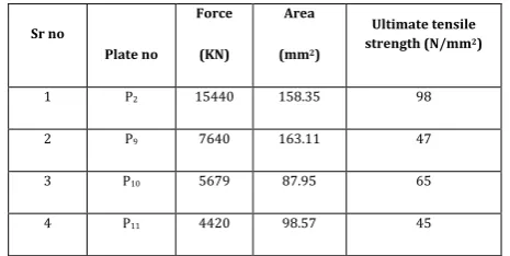
[image:6.595.45.278.226.343.2]The process parameters selected were mainly tool rotational speed, welding speed and tool geometry etc. Tests are performed as per the ASTM Standards at TCR Advance Engineering at Vadodara. A machined specimen is placed in the testing machine and load is applied to measure the resistance of a Material. The result for tensile strength for sample specimen is shown in Table 6.
Table 6: Tensile strength of sample specimen
Sr no
Plate no
Force
(KN)
Area
(mm2)
Ultimate tensile strength (N/mm2)
1 P2 15440 158.35 98
2 P9 7640 163.11 47
3 P10 5679 87.95 65
[image:6.595.38.271.390.534.2]4 P11 4420 98.57 45
Figure 12 shows the load vs displacement graph for varying thickness of plate on Tensile strength.
Fig-12: Tensile test graph (6 mm & 4 mm)
5. CONCULUSION
Important process parameters that control the quality of the weld are rotation speed (575 - 900 rpm) and traverse speed (3.16 - 8.16 mm/min) were performed to obtain defect free welded joints.
The following various conclusions summarize the present paper;
From this investigation, it has been found that tool profile cylindrical tool, transvers speed 3.37 mm/min and rotational speed is 900 rpm produced good tensile strength.
Mechanical properties of the joints increase with increase in tool rotational speed and reaches maximum at 500 to 575 rpm but again deceases with further increase in tool rotational speed.
The heat input from the tool shoulder was assumed to be the frictional heat. The coefficient of friction was
continuously adjusted to keep the calculated temperature from exceeding the material melting point. Increase in pin length decreases penetration depth on the back side of welded plate. It is also observed that more than 6 mm thickness of work piece is possible to weld by friction stir welding butt. The condition is to design a different tool for different thickness. While designing tool, the tool tip length should be less than the thickness of the base material i.e less than 0.25 to 0.8 times of the base the material thickness.
REFERENCES
[1] Chunlin Dong (2009), “Microstructure and mechanical
properties of friction stir welded joints in 2219-T6 Aluminum alloy”, Materials and Design 30, page 3460– 3467.
[2] Aritoshi, M., and Okita, K. 2002, “Friction welding of
dissimilar metals” Journal of Japan Welding Society 71-6(2002): 432-436.
[3] Sakayama, T.; Naito, Y.; Miyazakki, Y.; Nose, T.;
Murayma, G.; Saita, K.; Oikawa, H, “Dissimilar metal joining technologies for steel sheet and aluminum alloy sheet in auto body”, Nippon Steel Tech. Rep. 2013, 103, 91–98.
[4] Nandan, R.; DebRoy, T.; Bhadeshia, H.K.D.H, “Recent
advances in friction stir welding Process”, weldment structure and properties. Prog. Mater. Sci. 2008, 53, 980–1023.
[5] Mishraa, R.S.; Ma, Z.Y, “Friction stir welding and processing”; Mater. Sci. Eng. 2005, 50, 1–78.
[6] Fujii, H.; Cui, L.; Maeda, M.; Nogi, K, “Effect of tool
shape on mechanical properties and microstructure of friction stir welded aluminum alloys”, Mater. Sci. Eng. 2006, 419, 25–31.
[7] R. Rai, A. De, H. K. D. H. Bhadeshia and T. DebRoy,
“Review on friction stir welding tools, Science and Technology of Welding and Joining”, (2011) VOL16 NO4 325.
[8] Y. N. Zhang, X. Cao, S. Larose and P. Wanjara, “Review of
tools for friction stir welding and processing”, Canadian Metallurgical Quarterly, (2012) VOL 51 NO 3.
[9] Akos Meilinger and Imre Torok, “The importance of friction
stir welding tool”, Production Processes and Systems, vol. 6. (2013) No. 1. pp. 25-34.
[10] Cerri, E.; Leo, P, “Influence of high temperature thermal
treatment on grain stability and mechanical properties of medium strength aluminum alloy friction stir welds”, J. Mater. Process. Technol. 2011, 213, 75–83.
[11] Reynolds A.P., Lockwood W.D., Seidel T.U. 2000. Processing
- Property Correlation in Friction Stir Welds. Material Science Forum. 331-337. pp. 1719-1724.
[12] Frigaard Grong, Midling O.T. 1998, “Modeling of the Heat
© 2016, IRJET | Impact Factor value: 4.45 | ISO 9001:2008 Certified Journal
| Page 32
[13] Chen C.M., Kovacevic R. 2003, “Finite Element Modeling of
Friction Stir Welding-Thermal and Thermo-Mechanical Analysis”, International Journal of Machine Tools and Manufacture. 43: 1319-1326.
[14] Colegrove P. A. and Shercliff H. R. 2003, “Experimental and
Numerical Analysis of Aluminum Alloy 7075-T7351 Friction Stir Welds”, Science and Technology of Welding and Joining. 8, 5, IoM Communications Ltd. pp. 360-368.
[15] Buffa G., Huaa J., Shivpuri R., Fratini L. 2006. “A
continuum based FEM model for friction stir welding-model development”, Journal of material science and engineering, A419. pp. 389-396.
[16] Chao Y.J. and Qi X. 1998, “Thermal and Thermo
mechanical Analysis of Friction Stir Joining of AA6061-T6”, Journal of Mat. Process and Manufacturing. Sci. pp. 215-233.
[17] Chao Y.J., Qi X., Tang W. 2003, Heat Transfer in Friction
Stir Welding-Experimental and Numerical Studies. ASME J. Manuf. Sci. and Eng. 25: 138-145.
BIOGRAPHIES
Mr Piyush T Patel, (M.Tech. with specialization in CAD-CAM), having a 3.5 years of experience in academics. Presently he is working as Assistant Professor in CGPIT, UTU, Bardoli.
Mr Sachin D Patel, (M.Tech. with specialization in Industrial Process Equipment Design), having a 4 years of experience in academics. Presently he is working as Assistant Professor in CGPIT, UTU, Bardoli.