Abstract— In this paper, a simple Inset fed Microstrip patch
antenna for ISM band on laminated paper-based substrate is presented for the first time. Paper has emerged as one of the low costs, flexible, eco-friendly organic substrate which is extensively used for wearable body area network (WBAN) applications. But, one of the most important drawbacks of paper-based substrate is that, it is hydrophilic which degrades the performance characteristics of the designed antenna. To mitigate the problem of performance degradation due to ambient humidity of the environment and prolong the lifetime of paper-based electronics, the designed antenna is printed on the paper-based substrate laminated with transparent sheet. The design of the antenna requires the RF characterization of paper with lamination in terms of dielectric constant and loss tangent. Two methods, a cavity perturbation and a transmission line method are utilized for RF characterization of the laminated paper-based substrate. Finally, an inset fed microstrip patch is designed for 2.4 GHz which covers ISM band in free space. Also, its performance characteristics in the vicinity of human body (human arm) is analyzed in terms of SAR which is found to be within the SAR limit provided by FCC guidelines. The simulation and measurement results are in good agreement which confirms the characterization of substrate and the designed antenna is suitable for body area network.
Index Terms— BAN, laminated Paper based Substrate,
transparent sheet, SAR, WLAN.
I. INTRODUCTION
In last few years, flexible electronics has emerged as an attractive candidate for wearable body area network applications. Several low-cost flexible substrates like cotton textile, polyester, PET, denim, jute, wool, leather, rubber have been mentioned in many researches for flexible electronics [1-2].
In this decade, paper has emerged as one of the ultimate solution for low cost flexible electronics due to its low profile and conformability.[3]Many antennas have been reported in recent years on paper based substrate like PIFA for WLAN [4], Z shaped CPW fed monopole for GPS[5], RFID UHF antenna [6-7] and GPS, Wimax, Hiperlan/2, WLAN [8-10].
Manuscript received 1st July, 2019 revised August 3rd, 2019.
S. Kumari is pursuing Ph.D from Department of Electronics and Communication Engineering, Birla Institute of Technology, Mesra, Ranchi, Jharkhand, India-835215. Phone: +91 9431591755, e-mail: sakshi501@gmail
V. R. Gupta is working as professor in the Department of Electronics and Communication Engineering, Birla Institute of Technology, Mesra, Ranchi, Jharkhand, India-835215 e-mail: [email protected]
But none of the above has addressed the problem due to humidity. The electrical characteristics of the paper is bound to change, when humidity is absorbed by the paper. Hence in the humid environment the characteristic of the designed antenna will also change. In this paper the designed antenna is proposed on the laminated paper based substrate. Lamination of the paper avoids the absorption of the humidity by the paper.
The design process requires the characterization of the laminated paper. Two electromagnetic methods, transmission line method [11-12] and cavity resonator method [13-14] are utilized for the RF characterization i.e. dielectric constant (εr) and loss tangent (tan δ) of the paper and the transparent sheet. Transmission line method characterizes the substrate over the range of the frequency, whereas the resonant method gives more accurate results at a particular frequency.
II. MATERIALCHARACTERIZATION
The material characterization of paper has already been performed by many researchers in recent years using and transmission line method [11-12.], cavity perturbation method [13-14], T resonator [15], ring resonator method [16] But as Paper is an unconventional substrate with its wide accessibility of different types that varies in texture, coating, thickness, density including its relative permittivity and loss tangent. Therefore, its electromagnetic characterization (dielectric constant and loss tangent) is an essential step prior to any on-paper antenna design. Moreover, the transparent sheet used for laminating the paper substrate also need characterization.
A. Cavity Resonator Method
The first method that is adopted for material characterization is cavity resonator method which gives exact values of relative permittivity and loss tangent at desired frequency. The measurement set up consists of vector network analyzer (VNA), and 85071E Split post dielectric resonators (SPDR). The measurement of dielectric properties involves the measurement of resonant frequency and quality factor of an unloaded cavity (empty) and loaded cavity with material under test. The cylindrical shaped solid sample of paper is prepared and used for test. The dielectric constant of material under test (MUT) is calculated on the basis of variation in volume, frequency and Q-factor. Fig. 1 demonstrates the measurement set up for dielectric characterization of paper substrate. The formulas used for the material characterization are as follows [17]:
Real part of the dielectric constant is:
S. Kumari, Member IAENG and V. R. Gupta
(1) Imaginary part of the dielectric constant is:
(2)
Where,
𝑓𝑐 = Resonant Frequency of the Empty Resonator
𝑓𝑠 = Resonant Frequency of the loaded resonator with material under test (MUT)
𝑄𝑐 = Q- factor of Empty Cavity
𝑄𝑠 = Q- factor of Cavity loaded with MUT
𝑉c = Volume of Empty cylindrical Resonator.
𝑉s = Volume of Material under test (MUT) inside the cylindrical Resonator.
Table I shows the dielectric characterization calculation of paper and transparent sheet. The measured relative permittivity of paper and loss tangent are 2.8 and 0.035 respectively at 2.45 GHz while that of transparent sheet are 2.45 and 0.018 respectively.
[image:2.595.57.266.314.482.2]Fig. 1 Measurement set up for dielectric characterization by cavity resonator method
TABLE I
DIELECTRIC CHARACTERIZATION OF PAPER AND TRANSPARENT SHEET BY CAVITY RESONATOR METHOD
Parameters Paper Transparent sheet
𝑓𝑐(GHz) 10.9 10.9
𝑓𝑠(GHz) 8.75 9.69
𝑄𝑐 363.33 363.33
𝑄𝑠 33.65 96.9
𝑉c (mm3) 12386 12386
𝑉s (mm3) 803.84 529.87
2.8 2.45
0.0987 0.044
Loss tangent 0.035 0.018
B. Transmission Line Method
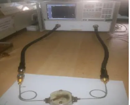
Two microstrip lines of 50 ῼ each are fabricated on the material under test whose dielectric constant is to be measured. The difference between the lengths of both transmission lines are kept as large as possible for getting precise results [11]. Fig.2 shows the measurement set-up of dielectric characterization of paper. The calibrated phase difference of
scattering parameters (S21) of transmission lines is measured which gives the effective dielectric constant [12] as:
(3)
Where,
Δθ is phase difference
ΔL is difference between lengths of two transmission lines
c is speed of light f is frequency
The relative dielectric constant of material is given as:
(4)
Where, x is given as
Where, h is the height of substrate’s height w is width of transmission line’s width
The Scattering parameters (S21) are measured over the frequency range 1 GHz to 3 GHz by the vector network analyzer. The measured difference of phases (S21 in degrees) of both transmission lines (100 mm and 50 mm of 4 mm thickness) gives the dielectric constant of material. Table II and Table III shows the dielectric constant calculation using equation (3) and (4) for paper and transparent sheet respectively. This method is also adopted for the extraction of loss tangent of paper and transparent sheet substrate over the frequency range 1- 3 GHz according to [18]:
(5)
Where, is attenuation constant λ0 is wavelength in free space
is effective relative permittivity is the relative permittivity
The loss tangent of paper and transparent sheet at 2.44 GHz are 0.0349 and 0.0181 respectively, calculated according to (5).
Fig.2. Measurement set up for dielectric characterization of paper by transmission line method
(a) 100 mm transmission line
[image:2.595.41.289.557.676.2] [image:2.595.305.542.616.758.2]TABLE II
DIELECTRIC CONSTANT MEASUREMENT OF PAPER BY TRANSMISSION LINE METHOD
Freq [GHz]
Phase difference (degrees)
Effective Relative Permittivity
Relative Permittivity (εr)
1 -10.4287371 2.273734279 2.804518311
1.2 -11.80641111 2.274737349 2.805941609
1.4 -10.58068248 2.28832875 2.825227031
1.6 -12.09041342 2.290226306 2.827919555
1.8 -13.59911493 2.291831699 2.830197515
2 -12.07798048 2.295459643 2.835345361
2.2 -15.41696844 2.303479465 2.84672503
2.4 -18.12511881 2.304668259 2.84841186
2.6 -19.63412048 2.311187309 2.85766202
2.8 -21.1566075 2.332761791 2.888274978
3 -22.66326896 2.336310947 2.893311028
TABLE III
DIELECTRIC CONSTANT MEASUREMENT OF TRANSPARENT SHEET BY TRANSMISSION LINE METHOD
Freq [GHz]
Phase difference (degrees)
Effective Relative Permittivity
Relative Permittivity (εr)
1 -15.8813422 1.863662314 2.447547072
1.2 -19.0594203 1.864016265 2.448140315
1.4 -22.171805 1.853270621 2.430130006
1.6 -25.4373337 1.867652282 2.454234485
1.8 -28.6180647 1.867791204 2.454467327
2 -31.7542704 1.862675062 2.445892383
2.2 -34.9387401 1.863639604 2.44750901
2.4 -38.1017225 1.86234248 2.445334956
2.6 -41.3015644 1.864571843 2.449071496
2.8 -44.4955818 1.865995234 2.451457179
3 -47.6916987 1.867393692 2.453801074
The transmission line method shows that there is very slight variation in the measured values of dielectric constants and the loss tangents of the paper and the transparent sheet over the desired range of frequencies. At the centre frequency of ISM band that is at 2.44 GHz, the measured value of dielectric constants and the loss tangents using cavity resonant method are 2.8 and 0.035 respectively for the paper while that for transparent sheet are 2.45 and 0.018 respectively. These values have been considered for antenna design.
III. ANTENNA DESIGN
[image:3.595.40.286.81.267.2] [image:3.595.41.291.299.491.2]The Inset fed Microstrip Patch configuration is designed on laminated paper-based substrate because of its simplicity in modeling and low fabrication cost [19-20]. The detailed optimized dimension of proposed antenna for 2.44 GHz is listed in Table IV. while Fig.3 shows the geometry of proposed antenna design.
TABLE IV
DETAILED DIMENSION OF PROPOSED ANTENNA
Fig 3. Proposed Antenna Design
IV. RESULTANDDISCUSSIONS
The designed antenna is simulated using HFSS software and its prototype is fabricated which is depicted in Fig. 4 The performance characteristics of Inset fed Microstrip Patch antenna in free space and on human arm is investigated and presented below:
A. Antenna performance in free space
The reflection coefficient is measured using Vector Network Analyzer and compared with the simulated results which shows that they are in good agreement. This comparison also confirms that the characterization of the laminated sheet is correct. Fig. 5 shows the comparison of simulated and measured reflection coefficient (S11) of the designed antenna on paper laminated with transparent sheet substrate. It can be inferred from the figure that both simulated and measured bandwidth of designed antenna resonating at 2.44 GHz covers the entire ISM band (2.4 -2.4835 GHz)
Fig.4. Prototype of fabricated antenna Antenna Parameters Dimensions (mm)
Substrate ( Lsub x Wsub) 60.4 x 53
Ground (Lg x Wg) 60.4 x 53
Patch ( Lpatch x W patch) 36.7 x 44.8
Feed (Lf x Wf ) 16.5 x 5
Inset Gap (Ig) 1
Inset Length (Li) 11.2
[image:3.595.364.497.621.750.2]Fig.5. Simulated and Measured Reflection coefficient of Inset fed Microstrip patch Antenna on laminated paper-based substrate.
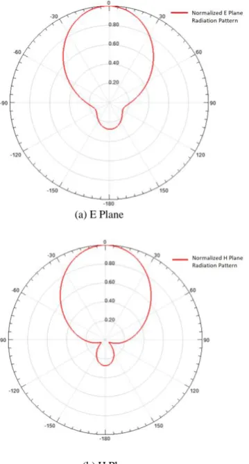
It is evident from the Fig.6 that at the radiation pattern exhibits almost omnidirectional characteristic. The peak gain for the designed antenna for ISM band is 1.85 dB.
The E Plane and H plane radiation pattern at 2.44 GHz are depicted in Fig. 6.
(a) E Plane
[image:4.595.58.293.57.234.2](b) H Plane
Fig.6. Normalized Radiation Pattern at centre frequency of ISM band
B. Antenna performance when placed on human arm
The interaction of antenna with the body parts depends on the electrical properties of body tissues at different frequencies. Hence the electrical properties of biological tissues are also characterized according to frequency of application. The
antenna can be placed anywhere on the human body for body area network applications, but for easy handling and convenience, the human arm is chosen.
The cylindrical human arm is modelled in HFSS, considering the biological tissue’s conductivity, permittivity and loss tangent at 2.44GHz [21] for evaluating antenna performance in vicinity of human arm which is depicted in Fig.7. Table V. shows the dielectric characterization of body tissues at 2.44 GHz.
TABLE V
[image:4.595.65.245.353.688.2]DIELECTRIC CHARACTERIZATION OF BODY TISSUES OF HUMAN ARM AT CENTER FREQUENCY OF ISM BAND
Fig.7 Human Arm Modelling
Fig.8. On Body (human arm) Measured and Simulated reflection Coefficient (S11) of antenna
The simulated and measured reflection coefficient (S11) of inset fed microstrip patch antenna on laminated paper-based substrate when placed on human arm is shown in Fig. 8. The simulated bandwidth is 0.09GHz covering frequency range 2.40GHz to 2.49GHz while the measured bandwidth is 0.12 GHz covering frequency range 2.4GHz to 2.52GHz, still covering the ISM band.
Body Tissues
Thickness
(mm)
Conductivity
(Siemens/m)
Dielectric Constant
Loss Tangent
Skin 2 1.46 38 0.28
Fat 2 0.1 5.28 0.14
Muscle 30 1.73 52.7 0.24
Fig.9. SAR plot of Antenna placed on human arm
The peak SAR due to the proposed antenna for ISM band is 0.86Watt/kg as depicted in Fig. 9 which is within the recommended SAR limit by FCC guidelines i.e. 4 watt/Kg for human arm/forearm [22]. Hence the proposed antenna on laminated paper-based substrate can be safely used for the BANs. Next the designed antenna was exposed to the humidity for several days as depicted in Fig. 10. But as the paper substrate was laminated with the transparent sheet, no variation in the reflection coefficient characteristics of antenna was observed even after 30 and 60 days.
Fig.10. Reflection Coefficient characteristics of laminated Paper based antenna
V. CONCLUSION
Flexible substrates are required for the wearable body area network as it provides the wearing comfort. Paper substrate, being one of the promising candidates as a flexible substrate has been considered in this paper.
The novelties of this paper include the lamination of the paper with a transparent sheet and its RF characterization to mitigate the problem of humidity absorption, which degrades the designed antenna performance. Initially, the characterization of transparent sheet and paper used for laminating low cost paper-based substrate for making it hydrophilic is done. The characterized laminated paper is then used for the design and fabrication of patch antenna for ISM band. The comparison of measured and simulated results shows excellent agreement. This also validates the characterization of laminated paper-based substrate. Electromagnetic exposure of antenna at desired band is also analyzed and found to be 0.86 Watt/Kg, which is within FCC guidelines and makes the antenna suitable for wearable applications.
REFERENCES
[1] P.J. Soh, G. A. E. Vandenbosch, S. L. Ooi and N. M. Rais, “Design of a broadband all textile slotted PIFA”, IEEE Transactions on Antennas and Propagation, vol. 60, no.1, pp. 379- 384, 2012.
[2] I. Gil, and R. F. García, “Wearable PIFA antenna implemented on jean substrate for wireless body area network”, Journal of Electromagnetic Waves and Applications, 2017, pp.1-11.
[3] A. H. Rida, “Conductive inkjet printed antennas on flexible low-cost paper-based substrate for RFID and WSN applications”, MS Thesis, GIT, May 2009.
[4] D. E. Anagnostou, A. A. Gheethan, A. K. Amert, and K. W. Whites, “A direct-write printed antenna on paper-based organic substrate for flexible displays and WLAN applications” Journal of Display Technology, vol.6, no.11, pp.558-564, 2010.
[5] A. M. Mansour, N. Shehata, B. M. Hamza and M. R. M. Rizk “Efficient Design of flexible and low-cost paper-based inkjet-printed antenna”,
International Journal of Antennas and Propagation, vol.2015, pp.1-6,
2015.
[6] S. Kim, A. Georgiadis, and M. M. Tentzeris, “Design of inkjet-printed RFID-based sensor on paper: single- and dual-tag sensor topologies”,
Sensors, vol.18, no.1958, 2018.
[7] A. Rida, L. Yang, R. Vyas, and M. M. Tentzeris, “Conductive inkjet printed antennas on flexible low-cost paper-based substrates for RFID and WSN applications”, IEEE Antennas and Propagation Magazine,
vol. 51, no.3, pp.13-23,2009.
[8] H. F. Abutarboush and A. Shamim, “Paper-based inkjet-printed triband U-slot monopole antenna for wireless applications”, IEEE Antennas
and Wireless Propagation Letters, vol.11, pp.1234-1237,2012.
[9] W. N. N. W. Marzudi, Z. Z.Abidin, S.H. Dahlan, K.N. Ramli, and M.R.Kamarudin, “Performance of star patch antenna on a paper substrate material”, ARPN Journal of Engineering and Applied
Sciences, vol.10, no.19, pp.8606-8612,2015.
[10] D.S. Marotkar, and P.L.Z. Yeshwantrao, “Microstrip antenna with Photographic paper substrate for WLAN”, International Journal of
Informatics and Communication Technology, vol.7, no.2, pp. 67-70,
2018.
[11] N. K. Das, S. M. Voda, and D. M. Pozar, “Two methods for the measurement of substrate dielectric constant”, IEEE Trans Microwave
Theory Tech, vol. 35, pp.636-642, 1987.
[12] S. H. Chang, H. Kuan, H.W. Wu, R.-Y. Yang, and M.-H. Weng “Determination of Microwave Dielectric Constant by Two Microstrip Line Method Combined with EM Simulation, Microwave and Optical
Technology Letters, vol. 48, no. 11, pp. 2199 – 2201, 2006.
[13] A. Rida, L. Yang, and M. M. Tentzeris , “Design and characterization of novel paper-based inkjet-printed UHF antennas for RFID and sensing applications”, in IEEE Conference, 2007.
[14] H. P. Phan, T. P. Vuong, P. Benech, P. Xavier, and P. Borel, “Printed flexible wideband microstrip antenna for wireless applications”, in
International Conference on Advanced Technologies for
Communications (ATC), pp.384-387, 2016.
[15] S. Kim, B. Cook, T. Le, J. Cooper, H. Lee, V. Lakafosis, R. Vyas, R. Moro, M.Bozzi, A. Georgiadis, A.Collado, and M.M.Tentzeris, “Inkjet printed antennas, sensors and circuits on paper substrate”, IET
Microwave and Antenna Propagation, vol.7, no.10, pp. 858–868, 2013.
[16] A. Rida, L.Yang, R. Vyas, S.Bhattacharya and M.M. Tentzeris,“Design and Integration of Inkjet printed Paper-based UHF Component for RFID and Ubiquitous Sensing Applications”, in Proceedings of the37th
European Microwave Conference, Germany, 2007.
[17] M.S. Venkatesh and G.S.V. Raghavan, “An overview of dielectric properties measuring techniques”, Canadian Biosystems Engineering, vol.47, pp.7.15-7.30, 2005.
[18] D. Thompson, G. Ponchak, M. M. Tentzeris, J. Papapolymerou, “Characterization of LCP material and transmission lines on LCP substrates from 30 to 110GHz,” IEEE Trans. Microwave Theory and
Tech., vol. 52, no. 4, pp.1343-1352, 2004.
[19] R. Garg, P. Bhatia, I. Bahl and A. Ittipiboon, “Microstrip Antenna
Design Handbook", Artech House Boston, London, 2000.
[20] C. A. Balanis, “Antenna Theory: Analysis and Design”, 3rd ed., John
Wiley & Sons, Hoboken, New Jersey, 2005.
[21] Calculation of the Dielectric Properties of Body Tissues in the frequency range 10 Hz – 100 GHz, Italian National Research Council, Institute of Applied Physics.
Available: http://niremf.ifac.cnr.it/tissprop/htmlclie/htmlclie.php