NONRESIDENT
TRAINING
COURSE
October 1997
Information Systems
Technician Training Series
Module 5—Communications Center
Operations
NAVEDTRA 14226
NOTICE
DISTRIBUTION STATEMENT A: Approved for public release; distribution is unlimited. Although the words “he,” “him,” and
PREFACE
By enrolling in this self-study course, you have demonstrated a desire to improve yourself and the Navy. Remember, however, this self-study course is only one part of the total Navy training program. Practical experience, schools, selected reading, and your desire to succeed are also necessary to successfully round out a fully meaningful training program.
COURSE OVERVIEW: In completing this nonresident training course, you will demonstrate a knowledge of the subject matter by correctly answering questions on the following subjects: Center Operations, Voice Communications, Emission Control, and Cryptosecurity.
THE COURSE: This self-study course is organized into subject matter areas, each containing learning
objectives to help you determine what you should learn along with text and illustrations to help you understand the information. The subject matter reflects day-to-day requirements and experiences of personnel in the rating or skill area. It also reflects guidance provided by Enlisted Community Managers (ECMs) and other senior personnel, technical references, instructions, etc., and either the occupational or naval standards, which are listed in the Manual of Navy Enlisted Manpower Personnel Classifications
and Occupational Standards, NAVPERS 18068.
THE QUESTIONS: The questions that appear in this course are designed to help you understand the
material in the text.
VALUE: In completing this course, you will improve your military and professional knowledge. Importantly, it can also help you study for the Navy-wide advancement in rate examination. If you are studying and discover a reference in the text to another publication for further information, look it up.
1997 Edition Prepared by RMCS(SW/AW) Deborah Hearn and
DPC(SW) Walter Shugar, Jr.
Published by
NAVAL EDUCATION AND TRAINING PROFESSIONAL DEVELOPMENT
AND TECHNOLOGY CENTER
ii
Sailor’s Creed
“I am a United States Sailor.
I will support and defend the
Constitution of the United States of
America and I will obey the orders
of those appointed over me.
I represent the fighting spirit of the
Navy and those who have gone
before me to defend freedom and
democracy around the world.
I proudly serve my country’s Navy
combat team with honor, courage
and commitment.
CONTENTS
CHAPTER PAGE
1. Center Operations. . . 1-1
2. Voice Communications . . . 2-1
3. Emission Control . . . . . 3-1
4. Cryptosecurity . . . 4-1
APPENDIX
I. Glossary . . . AI-1
II. Glossary of Acronyms and Abbreviations . . . AII-1
III. References Used to Develop the TRAMAN. . . AIII-1
INDEX.. . . INDEX-1
SUMMARY OF THE RADIOMAN
TRAINING SERIES
MODULE 1
Administration and Security—This module covers Radioman duties relating to administering AIS and communication systems. Procedures and guidance for handling of classified information, messages, COMSEC material and equipment, and AIS requirements are discussed.
MODULE 2
Computer Systems—This module covers computer hardware startup, including peripheral operations and system modification. Other topics discussed include computer center operations, media library functions, system operations, and troubleshooting techniques. Data file processes, memory requirements, and database management are also covered.
MODULE 3
Network Communications—This module covers network administration, LAN hardware, and network troubleshooting. Related areas discussed are network confilguration and operations, components and connections, and communication lines and nodes.
MODULE 4
Communications Hardware—This module covers various types of communications equipment, including satellites and antennas. Subjects discussed include hardware setup procedures, COMSEC equipment requirements, distress communications equipment, troubleshooting equipment, satellite theory, and antenna selection and positioning.
MODULE 5
Communications Center Operations—This module covers center operations, including transmit message systems, voice communications, center administration, quality control, and circuit setup/restorations. Guidelines for setting EMCON and HERO conditions and cryptosecurity requirements are also discussed.
CREDITS
Trademark Credits
vi
INSTRUCTIONS FOR TAKING THE COURSE
ASSIGNMENTS
The text pages that you are to study are listed at the beginning of each assignment. Study these pages carefully before attempting to answer the questions. Pay close attention to tables and illustrations and read the learning objectives. The learning objectives state what you should be able to do after studying the material. Answering the questions correctly helps you accomplish the objectives.
SELECTING YOUR ANSWERS
Read each question carefully, then select the BEST answer. You may refer freely to the text. The answers must be the result of your own work and decisions. You are prohibited from referring to or copying the answers of others and from giving answers to anyone else taking the course.
SUBMITTING YOUR ASSIGNMENTS
To have your assignments graded, you must be enrolled in the course with the Nonresident Training Course Administration Branch at the Naval Education and Training Professional Development and Technology Center (NETPDTC). Following enrollment, there are two ways of having your assignments graded: (1) use the Internet to submit your assignments as you complete them, or (2) send all the assignments at one time by mail to NETPDTC.
Grading on the Internet: Advantages to Internet grading are:
• you may submit your answers as soon as you complete an assignment, and
• you get your results faster; usually by the next working day (approximately 24 hours).
In addition to receiving grade results for each assignment, you will receive course completion confirmation once you have completed all the
assignments. To submit your assignment answers via the Internet, go to:
http://courses.cnet.navy.mil
Grading by Mail: When you submit answer
sheets by mail, send all of your assignments at one time. Do NOT submit individual answer sheets for grading. Mail all of your assignments in an envelope, which you either provide yourself or obtain from your nearest Educational Services Officer (ESO). Submit answer sheets to:
COMMANDING OFFICER NETPDTC N331
6490 SAUFLEY FIELD ROAD PENSACOLA FL 32559-5000
Answer Sheets: All courses include one “scannable” answer sheet for each assignment. These answer sheets are preprinted with your SSN, name, assignment number, and course number. Explanations for completing the answer sheets are on the answer sheet.
Do not use answer sheet reproductions: Use
only the original answer sheets that we provide—reproductions will not work with our scanning equipment and cannot be processed.
Follow the instructions for marking your answers on the answer sheet. Be sure that blocks 1, 2, and 3 are filled in correctly. This information is necessary for your course to be properly processed and for you to receive credit for your work.
COMPLETION TIME
PASS/FAIL ASSIGNMENT PROCEDURES
If your overall course score is 3.2 or higher, you will pass the course and will not be required to resubmit assignments. Once your assignments have been graded you will receive course completion confirmation.
If you receive less than a 3.2 on any assignment and your overall course score is below 3.2, you will be given the opportunity to resubmit failed assignments. You may resubmit failed assignments only once. Internet students will
receive notification when they have failed an assignment--they may then resubmit failed assignments on the web site. Internet students may view and print results for failed assignments from the web site. Students who submit by mail will receive a failing result letter and a new answer sheet for resubmission of each failed assignment.
COMPLETION CONFIRMATION
After successfully completing this course, you will receive a letter of completion.
ERRATA
Errata are used to correct minor errors or delete obsolete information in a course. Errata may also be used to provide instructions to the student. If a course has an errata, it will be included as the first page(s) after the front cover. Errata for all courses can be accessed and viewed/downloaded at:
http://www.advancement.cnet.navy.mil
STUDENT FEEDBACK QUESTIONS
We value your suggestions, questions, and criticisms on our courses. If you would like to communicate with us regarding this course, we encourage you, if possible, to use e-mail. If you write or fax, please use a copy of the Student Comment form that follows this page.
For subject matter questions:
E-mail: [email protected] Phone: Comm: (850) 452-1501
DSN: 922-1501 FAX: (850) 452-1370 (Do not fax answer sheets.) Address: COMMANDING OFFICER
NETPDTC N311
6490 SAUFLEY FIELD ROAD PENSACOLA FL 32509-5237
For enrollment, shipping, grading, or completion letter questions
E-mail: [email protected] Phone: Toll Free: 877-264-8583
Comm: (850) 452-1511/1181/1859 DSN: 922-1511/1181/1859
FAX: (850) 452-1370 (Do not fax answer sheets.) Address: COMMANDING OFFICER
NETPDTC N331
6490 SAUFLEY FIELD ROAD PENSACOLA FL 32559-5000
NAVAL RESERVE RETIREMENT CREDIT
If you are a member of the Naval Reserve, you may earn retirement points for successfully completing this course, if authorized under current directives governing retirement of Naval Reserve personnel. For Naval Reserve retire-ment, this course is evaluated at 3 points. (Refer to Administrative Procedures for Naval Reservists on Inactive Duty, BUPERSINST
Student Comments
Course Title:
Information Systems Technician Training Series Module 5—Communications Center Operations NAVEDTRA: 14226 Date:
We need some information about you:
Rate/Rank and Name: SSN: Command/Unit
Street Address: City: State/FPO: Zip
Your comments, suggestions, etc.:
Privacy Act Statement: Under authority of Title 5, USC 301, information regarding your military status is requested in processing your comments and in preparing a reply. This information will not be divulged without written authorization to anyone other than those within DOD for official use in determining performance.
CHAPTER 1
CENTER OPERATIONS
Upon completing this chapter, you should be able to do the following: Identify the procedures for transmitting messages via automated systems and manual circuits.
Identify the procedures for monitoring and reporting of circuit backlogs. Identify the steps to verify broadcast number continuity.
Determine the procedures for preparing, updating, and verifying the command guard list (CGL) and the master station log (MSL).
Identify the procedures to verify STU-III systems parameters for remote/dial-in users and explaremote/dial-in the need to set up and operate the STU-III termremote/dial-inals with remote/dial-in users.
Determine the procedures for the preparation of the communications plan. Identify the steps to reset communications systems to RADAY.
Determine communications protocols applied to circuit set up/restorations. List the steps to activate, deactivate, and place communications circuits in standby, set up, or restoration.
Identify the procedures to transmit or receive cryptographic keying material via OTAT/OTAR.
Define the steps to analyze network capacity and reliability.
Telecommunications capabilities are continually advancing as technology improves. Because of advances in technology, we are seeing great improvements in the quality and speed of communications, and an increase in our information transfer capabilities. The Navy’s modern automated systems greatly reduce writer-to-reader times in message handling, and the volume of messages that can be processed is steadily increasing.
ASHORE AUTOMATED
TELECOMMUNICATIONS SYSTEMS
Two new shore command systems that are coming on-line in the 1990s are the Navy Standard Teleprinter Ashore (NSTA) and the Manual Relay Center
Modernization Program (MARCEMP). We will discuss these two new systems as well as the other in-place automated shore systems and their interface components.
NAVY STANDARD TELEPRINTER ASHORE
With the introduction of the Navy Standard Teleprinter (NST) at afloat commands, there was a need to replace antiquated communications systems ashore with a system compatible with the NSTs. To meet this need, the Navy has developed the Navy Standard Teleprinter Ashore (NSTA) program.
associated software. The PCMT (shown in figure l-l) is a PC-based microcomputer. The PCMT is a major step toward modernizing the entire Naval Telecommunications System.
Personal Computer Message Terminal
The Personal Computer Message Terminal (PCMT) is a remarkable military message-processing software package that runs on a combination of IBM-compatible PC- or AT-class desktop microcomputers and input/output devices called bus interface units (BIUs). The PCMT has the following advantages:
For sites having a message relay requirement, the PCMT system eliminates handling torn paper tape.
For small naval telecommunications centers (NTCs), the PCMT provides a sophisticated, easy-to-use automated message-handling system.
For Local Digital Message Exchange (LDMX) or Naval Communications Processing and Routing System (NAVCOMPARS) subscribers that must be served remotely, the PCMT can provide an excellent, low-cost remote terminal capability. Received traffic can be reviewed at a terminal and selected messages shifted to a printer when a hardcopy is needed. The system will allow the operator to compose and save any number of partially completed pro forma messages. Subsequently, these messages can quickly and easily be retrieved, completed, and sent whenever needed.
The PCMT allows messages to be exchanged via diskette media. For users who wish to exchange AUTODIN message traffic with their own
PC-Figure 1-1.—Personal Computer Message Terminal (PCMT) with printer.
1-2
based systems, the PCMT provides an excellent vehicle for doing so.
PCMT System
The PCMT message-processing system is a store-and-forward system that provides full accountability for all messages transmitted and received. The PCMT consists of a microcomputer configured with an 84-key keyboard, monitor, hard disk, and one or two floppy diskette drives. The PCMT also includes a medium-speed printer for printing message logs and hard-copy messages when required. Bus interface units (BIUs) are required to interface between the PCMT and the automated shore systems.
The PCMT microprocessor has 640K (minimum) of random-access memory (RAM) and uses the Microsoft® Disk Operating System (MS/DOS). The PCMT has a 5 1/4- and 3 l/2-inch disk drive capability. The minimum hard disk has a capacity of 10 million bytes. The hard disk varies based on software and user storage requirements. The PCMT may have either a nonremovable or removable drive, depending upon the user’s security requirements.
The MS/DOS software is designed for a single workstation operation with operator-entered commands controlling the workstation. Powerful, easy-to-use message edit software will help the operator correct errors in input data from diskettes and generate messages. The monitors are monochrome except where the software has been coded to display pertinent information in color. In the next paragraphs, we will describe some of the capabilities of the PCMT.
The PCMT system assigns a message accountability number (MAN) to each complete or partial message processed. Once a MAN is assigned, the system reports each step in the processing of that message. This is done by automatically generated and on-demand log entries and on-demand message accountability reports. Message accountability reports identify all processing activity completed or pending for each message processed by the system.
The system also generates a log entry each time a complete or partial message is received, transmitted, or canceled. All messages received from or delivered to a diskette are further identified in the log entries and message accountability reports by the appropriate diskette volume identification.
[image:14.616.65.299.547.666.2]device. The operator can recall a message by providing a message accountability number (MAN), a component identification number (CIN), or a channel service number (CSN). The operator can also recall a message with an originating station routing indicator (OSRI), station serial number (SSN), or time of file (TOF).
The PCMT also provides significant paper reduction since information on receipt and delivery of message traffic is recorded on diskettes instead of paper. The PCMT stores messages on the hard disk until the operator requests delivery. The PCMT then outputs messages to a diskette, thereby reducing manual processing steps.
The PCMT system is setup so that narrative and data pattern (card image) traffic received from the serving LDMX and NAVCOMPARS can be delivered to the printer and/or diskettes. Data pattern traffic is usually delivered only to diskettes. Messages delivered to diskettes are segregated by routing indicators so that message centers receive only those messages addressed to them.
An operator can use the PCMT to enter a narrative or card image message, or create anew message using a simple keyboard/display screen editor. The terminal allows the operator to save a partially completed message on a diskette, recall it, and continue to edit it. At some communications centers, the operator can enter narrative or card image data pattern traffic prepared elsewhere.
Simple PC-based application programs that can be used in an office environment to review and prepare both narrative and card image messages are being developed. Once a day, the PCMT system will generate a summary report that identifies all traffic processed by the terminal during the previous 24-hour period.
The PCMT is the outgrowth of a program begun by COMNAVTELCOM (now COMNAVCOMTEL-COM) in 1982 to provide automation support for fleet message relay centers. The Navy had a continuing requirement to exchange message traffic over HF radio channels terminated at a relay site. Unfortunately, such channels impressed transmission garbles on any message they carried.
Since NAVCOMPARS required that message data presented by a TTY circuit be letter-perfect, NAVCOMPARS could not terminate such circuits directly. In the past, a message received on these circuits had to be punched out onto paper tape and printed simultaneously. The fleet center operator would then examine the printed copy and, if there were no
errors, feed the paper tape into a reader that was on-line to NAVCOMPARS. If there was an error, either the ship would have to resend the message or the operator would have to recut the message’s paper tape on a Model 28 TTY.
The process was slow, manpower intensive, and error prone. The system built in response to this need is now what we call the Manual Relay Center Modernization Program (MARCEMP).
MANUAL RELAY CENTER MODERNIZATION PROGRAM
The Manual Relay Center Modernization Program (MARCEMP) was first certified for operational use in 1988 as part of the NSTA program. However, even before certification, it was recognized that the system could serve as the basis for a much more generalized low-cost message-processing system. The typical MARCEMP system is a PCMT configuration.
The MARCEMP provides significant automation support for all aspects of HF message relay operations within the fleet. Since all HF fill-period termination and primary ship-shore traffic circuits have been terminated directly into a state-of-the-art computer-based system, the need to handle tom paper tape has been completely eliminated.
The MARCEMP system automatically checks formal messages for errors and sends them on when no errors are found. The system also makes available to a fleet center operator an advanced, full-screen computer terminal editor. The operator can use the terminal editor to correct format errors in the message that occur due to transmission garbles. The terminal editor can also be used to carry on an operator-to-operator dialogue with afloat communications personnel to coordinate corrective action.
The system provides a complete message audit trail and detailed accountability reports, which help ensure that all traiffic is properly handled. Its modular and flexible design permits it to be easily tailored to meet the varying individual needs of the large or small fleet center. MARCEMP can handle up to 24 send and 24 receive circuits simultaneously. MARCEMP can also process approximately 3,500 narrative or operator-to-operator dialogue messages daily.
program. This version is configured as a single workstation. Version 3.0 can be configured as a multiple workstation or single workstation PCMT system to replace both the earlier version 1.0 MARCEMP and version 2.0 PCMT. The PCMT version 3.0 can do everything MARCEMP and PCMT version 2.0 can do—and much more.
GATEGUARD SUBSYSTEM
The GateGuard subsystem is an Automatic Digital Network (AUTODIN) Interface Terminal (AIT) that provides user office automation systems (OASs) a gateway to the AUTODIN system. (AUTODIN is discussed later.) GateGuard also acts as a security guard device; hence, the name GateGuard. The GateGuard subsystem will eventually allow commands (subscribers) to interface directly with the AUTODIN system. This direct interface eliminates the manual h a n d l i n g o f m e s s a g e s b y t h e s e r v i c i n g telecommunications center (TCC).
Currently, a servicing TCC processes (transmit and receive) message traffic from the AUTODIN system for its subscribers. The GateGuard subsystem will eventually eliminate the need for TCCs because subscribers will be able to process their own messages through GateGuard. Subscribers will also be able to route messages via their local area networks (LANs) using desktop computers.
The GateGuard system is comprised of three elements:
An AUTODIN Gateway Terminal (AGT),
A gateway communications link to an Automated Information System (AIS), and
A Guard Device (GD).
The AGT functions as a RIXT look-alike send-and-receive terminal connected to one of the AUTODIN subscriber terminals, such as the LDMX, NAVCOMPARS, or PCMT. The AGT serves as the primary AUTODIN interface point for a single organization.
The AGT has software that will operate on microcomputer systems designed to be operated by organization admin personnel. For example, in a small command, the AGT is located in the commanding officer’s outer office and is operated by the Yeoman or secretary.
The communications link connecting the AUTODIN Subscriber Terminal (AST) with the AGT passes through the Guard Device (GD). The main purpose of the GD is to assist in enforcing system security policy. Specifically, the GD serves to isolate sensitive data in the serving AST from data processed by the AGT. It does so by ensuring that each message processed has been properly encapsulated and assigned a security code that the AGT is cleared to process.
The serving AST provides long-term archive storage for all messages sent to or received from the AGT. When the AGT is served by an LDMX, an operator at the AGT is able to recall messages from that system automatically. The operator is also able to identify the desired message by its originator and date-time group, originating station routing indicator, station serial number, time of file, or by the processing sequence number assigned to the message by that system.
The following is a simplified description of how the GateGuard subsystem works:
Various offices in a command have desktop computers that are interconnected by the command’s LAN. Messages drafted on any computer in the system can be stored in a central computer. These messages can be accessed by any computer in the LAN. The messages can then be reviewed and checked for accuracy in format and content. When a message is released, the command sends it to the AUTODIN system via the GateGuard subsystem. At no time does the message leave the computer channels.
When messages are sent to subscribers via the AUTODIN system, the GateGuard subsystem will be able to identify messages for the various subscribers by plain language addresses (PLAs) or routing indicators (RIs). In some cases, GateGuard will use a key word or phrase in the message text to identify the subscriber for which the message is intended.
GateGuard will examine each message for which it accepts delivery responsibility, determine message completeness, and determine if it contains internally consistent security labels. If GateGuard detects any discrepancies, the software will not allow the message to be forwarded or delivered to a diskette. However, the message can still be routed to a local printer connected to the GateGuard subsystem.
AUTOMATIC DIGITAL NETWORK
The Automatic Digital Network (AUTODIN) is a worldwide computerized communications system. AUTODIN provides for the transmission of narrative and data pattern traffic on a store-and-forward basis.
AUTODIN provides reliable, secure, and efficient communications. AUTODIN also incorporates error detection and contains the highest speed transmission equipment currently available. AUTODIN is part of the Defense Communications System (DCS) and is managed by the Defense Communications Agency (DCA).
Interface equipments translate all AUTODIN inputs into common machine language, making AUTODIN compatible with many computer codes, speeds, and media, such as cards and tapes. Because of this, communications equipment within the NTS can be integrated into the AUTODIN system.
AUTODIN Switching Centers
The backbone of the AUTODIN system is the Automatic Switching Center (ASC). There are eight ASCs in the continental United States and five ASCs overseas (Europe and the Pacific).
The ASCs are interconnected into a digital network by trunk lines. Each center has local lines that link it to each subscriber (communications center) terminal. Messages entering the AUTODIN system at any of the subscriber terminals are forwarded through their respective switching centers. The ASCs accept messages from subscribers, determine the classifications and precedence of the messages, and relay the messages to the addressed subscribers.
AUTODIN Operational Modes
There are five AUTODIN system operational modes. These modes provide variation of speed and operation capabilities based on the equipment configurations of the message center subscribers. The following paragraphs describe each mode:
Mode I —A duplex operation with automatic
error and channel controls. Mode I operation allows independent and simultaneous two-way operation between two stations. The channel control characters acknowledge receipt of valid line blocks and messages or allow return of error information to the subscriber. The terminal
(switching center) responds automatically to these characters by continuing or stopping transmission and displaying action information to the operator. A magnetic tape terminal is an example of terminal equipment using mode I.
Mode II —A duplex operation normally
associated with TTY or teleprinter equipments with independent and simultaneous two-way operation capability. There are no automatic error and charnel controls in mode II operation. Message accountability is maintained through channel sequence numbers and service message actions.
Mode III —A duplex operation with automatic
error and channel controls but only one-way transmission capability. The return is used only for error control and channel coordination response. The mode III channel is reversible on a message basis. Control characters are used in the same manner as in mode I.
Mode IV —A unidirectional operation (send
only or receive only) without error control and channel coordination. The mode IV channel is nonreversible and is equivalent to half-duplex operation of mode II.
Mode V —A duplex operation, normally
associated with TTY or teleprinter equipment, with independent and simultaneous two-way transmission. Control characters acknowledge receipt of messages and display limited information to the operator. Message accountability is maintained through the use of channel sequence numbers.
Input and output (I/O) devices, such as teleprinters, provide the central AUTODIN computer with the necessary means to communicate with the user. Output devices provide the means for changing the computer-processed data into a form specified by or intelligible to the users. The selection of I/O devices depends on the specific use for which a computer is intended.
I/O devices use coded languages. These languages are:
ASCII Code —American Standard Code for
Information Interchange, eight-level paper tape; and
ITA #2 Code —American version of
international TTY alphabet, five-level paper tape.
Message Header Programming
At the beginning of each AUTODIN message is a header (format line 2) containing pertinent information on the destination of the message. The originator can address a message either to a single addressee or to multiple addresses. This system saves time and requires fewer communications facilities, since only one message is prepared by the originator and sent to the switching center.
The timing system contained in AUTODIN equipment briefly connects a switching center to each subscriber terminal in turn. Computer memories act as reservoirs for the incoming messages of each subscriber terminal. The computer is programmed to connect each terminal in turn during a cycle. Messages received in their entirety are scheduled for output to the addressees’ charnels as their turns arrive in the cycle.
AUTODIN has built-in safeguards that can detect almost any type of hardware or format error. Additionally, a complete (reference) copy of all relayed messages is kept on AUTODIN computer tape. A separate (journal) copy is made of only the addressee(s). Using this journal copy as an index enables the system to locate the reference copy of any message.
AUTODIN Tape Messages
The AUTODIN system is programmed to accept properly cut tapes and route them through the various switching centers and terminals en route to their ultimate destination. The system is then able to produce a tape and hardcopy for the designated addressee(s).
When preparing a message tape for the AUTODIN system, you must adhere to certain tape-cutting procedures. For example, format lines 1, 2, and 4 must not deviate; otherwise, the ASC will reject the message. The next paragraphs discuss the most important points on proper preparation of tape messages for transmission in the AUTODIN system.
ROUTING INDICATORS. —Within the
AUTODIN network, a message tape is routed through the AUTODIN system to the addressee(s) by a routing indicator. Routing indicators are combinations of not less than four nor more than seven letters.
A routing indicator begins with the letter R or Q. The letter R indicates that the routing indicator is part of the worldwide tape relay system. The letter Q indicates that the routing indicator is within a self-contained network within a command or theater.
The second letter of the routing indicator identifies the nation or international alliance to which the indicator belongs. For example, the letter U refers to the United States. Therefore, RU indicates that the message tape is part of the worldwide network and is destined to a station in the United States.
The third letter of the routing indicator identifies the geographical area in which a particular station is located or from which it is served. This is necessary for relay purposes because the second letter may indicate a large nation within which there are a number of subdivisions or stations. For example, many stations in the United States are designated by the third letter C. Therefore, the first three letters of “RUC” indicate that the tape is part of the worldwide network, destined for the United States, and to a certain geographical area within the United States.
The fourth and subsequent letters of a routing indicator designate relay and tributary stations within the tape relay network. Like the first three letters, the fourth and subsequent letters may vary, depending upon location, area, and other factors.
TRANSMISSION IDENTIFICATION (FORMAT LINE 1). —As a means of maintaining
traffic continuity, TTY terminals (modes II, IV, and V) must prefix each message header with a message transmission identification (TI). The ASC validates the elements in the TI. Modes I and III do not require format line 1. The TI is constructed without spaces and must be accurately prepared without corrections. For example, a correctly prepared TI might appear as follows:
VZCZCJTA (FIGS) 123 (LTRS) (2CR 1LF)
The elements of the TI and their meanings are as follows:
l V —Ensures that the first character of intelligence is not lost or garbled;
l ZCZ —Indicates the start of the message;
. JTA —Station/channel designator letters;
. xxx —Three-digit number indicating the sequential number of transmissions.
The station/channel designators vary for each channel and are determined by the status of the originating station. For example, if a minor relay or tributary station originates a TI to a major relay station, the first two characters consist of the fifth and sixth letters of the station routing indicator. The third character identifies the channel. Channel designators start with the letter A, progress alphabetically, and are assigned to all connected channels. For example, a tributary station having the routing indicator
RUWTABA would use the designator “ABA” for the first outgoing channel and “ABB,” “ABC,” and so on, for additional outgoing channels.
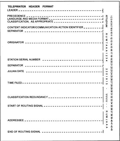
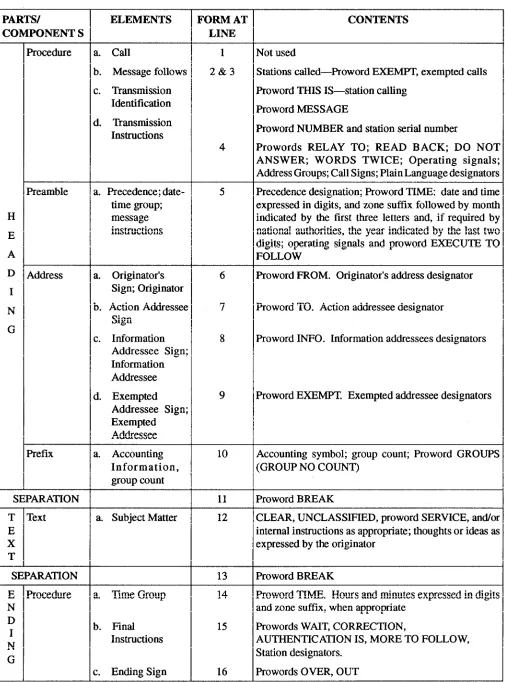
MESSAGE HEADER (FORMAT LINE 2). —The message header is a basic 43-position header
(figure 1-2). The message header is the starting point for the operator who is preparing the message tape. When preparing the header, the operator must remember that it must be letter-perfect.
The following paragraphs describe each position of the header:
Position 1 (Precedence) —The prosign Z
[image:19.612.99.497.233.699.2](FLASH), O (IMMEDIATE), P (PRIORITY), or R
(ROUTINE) is the first element. The prosign Y (YANKEE) is an emergency command precedence (ECP) and is assigned to emergency action messages (EAMs). The prosign Y indicates that a message has FLASH preemption capability. EAMs are processed ahead of all other traffic and interrupt lower precedence traffic already in processing within the AUTODIN system.
Positions 2 and 3 (Language and Media Format) —The language and media format (LMF)
[image:20.620.62.305.438.557.2]consists of two alphabetical characters. The LMF is the mode used to insert a message into the AUTODIN system. The LMF of the originating station is placed in position 2, and the LMF of the preferred output device of the addressee is placed in position 3. For example, in figure 1-2, positions 2 and 3 have the character T. The character Tin position 2 indicates that the originator’s transmitting mode is paper tape (TTY/teleprinter) (five-level ITA2 code). The character T in position 3 indicates that the output device at the receiving end will be paper tape (TTY) (five-level ITA2 code). If the character C was used in position 3, this would indicate that the message was prepared and transmitted on paper tape and the output device at the receiving message center would be magnetic tape. Automated Digital
Network (AUTODIN) Operating Procedures, JANAP
128, lists the LMFs used in the AUTODIN system.
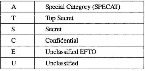
Position 4 (Classification) —The letters
authorized to indicate the message classification or special handling in this position are:
Positions 5 through 8 (Content Indicator Code [CIC]/Communication Action Identifier [CAI]) —These positions of the header are a
combination of either four letters or three letters and one number. These combinations are used to indicate message content and to provide identification for communications handling. For example, in figure 1-2, the CAI in positions 5 through 8 is ZYUW. This identifies the message as a narrative message. A CAI of ZFH2 would mean that the message is being forwarded to the addressee for information only. A CAI of ZYVW
would indicate that the message is a service message. A complete listing of these codes is found in JANAP 128.
Position 9 (Separator) —At this point in the
header, the operator must press the space bar to insert the TTYcode equivalent for space on the message tape.
Positions 10 through 16 (Originator) —The
appropriate routing indicator of the originating station is placed in these positions.
Positions 17 through 20 (Station Serial Number) —The station serial number (SSN) of the
sending station is inserted here. The SSN serves two specific purposes. First, when used in combination with the originator’s routing indicator, it provides positive identification for each transmission. Second, in the end of message (EOM) validation (discussed later in this section), the SSN appearing in format line 15 provides a means by which the ASCs can check for the existence of straggler messages.
The SSN is expressed in four numeric characters, beginning with 0001 and continuing consecutively through 9999. A new series begins when the number 9999 is reached. Operating stations may use SSNs to identify local activities, channels, or positions within a station by assigning each activity a specific block of numbers. For example, one station may be assigned numbers 0001 to 2000; the next station 2001 to 4000, and so on.
Position 21 (Separator) —This position requires
the same information as that for position 9.
Positions 22 through 24 (Julian Date) —The
Julian date is the date that the message was received from the originator for transmission by the communications center. The first day of the calendar year is Julian 001, and each day is numbered consecutively thereafter.
Positions 25 through 28 (Time Filed) —The time
filed is the time that the message was received from the originator by the communications center for transmission. Each filing time is expressed in Greenwich mean time (GMT) and must contain four numerical characters.
Positions 29 through 33 (Classification Redundancy) —For security reasons, the classification
designator used in position 4 is repeated here. Position 29 is filled with a hyphen as a sentinel. The classification designator in position 4 is repeated in positions 30 through 33.
Position 34 through end-of-routing signal (start-of-routing signal and addressees) —The positions
reserved for routing are made up of two sections: start-of-routing signal and the addressees’ routing indicators. The start-of-routing signal consists of two consecutive hyphens and will always precede the first addressee routing indicator. Addressee routing indicators are listed immediately following the start-of-routing signal. A message can have a maximum of 500 routing indicators in these positions. If a message contains 501 or more routing indicators, the message will require two separate transmission. In this case, all routing indicators that have the same first four letters should be in one transmission
End-of-Routing Signal —The end-of-routing
signal consists of a period (.) and is inserted in the position immediately following the last addressee routing indicator.
SECURITY WARNING (FORMAT LINE 4). —A security warning is the first component of
format line 4. The appropriate operating signal (ZNR or ZNY) will always be followed by a classification character repeated five times. The operating signal and classification characters are as follows:
ZNR UUUUU —For off-line encrypted messages
and classified messages transmitted in the clear;
ZNY EEEEE —For unclassified EFTO messages;
and
ZNY, followed by CCCCC, SSSSS, or TTTTT —For Confidential, Secret, or Top Secret
messages, respectively.
For SPECAT and SPECAT SIOP-ESI messages, the five redundant security characters are followed by an oblique (/) AAAAA for SIOP-ESI or BBBBB for all other SPECAT messages. For example, format line 4 for a Top Secret SPECAT message would be:
ZNY TTTTT/AAAAA(2CR, 1LF)
END OF MESSAGE (EOM) (FORMAT LINES 15 AND 16). —Format line 15 is the EOM validation
line that is used to inhibit suspected straggler messages. Format line 15 consists of the SSN in format line 2 preceded by the number sign (#). Format line 16 consists of the EOM functions. The EOM functions consist of normal teleprinter ending procedure when five-level Baudot code is used (2CR, 8LF, 4Ns, 12LTRS). However, for ASCII, 12 delete functions are used (12DEL). The EOM for the message with format line 2 shown in figure 1-2 would be as follows:
Format lines 1, 2, 4, and 5 must all be accurately prepared. Backspacing, lettering out, double-spacing, or using two or more FIGURES and LETTERS functions in sequence will cause the ASC to reject the message during attempted transmission from the originating station. The EOM validation appearing in format line 15 and the EOM function in format line 16 must be prepared in uninterrupted sequence, be letter-perfect, and be without corrections.
General Teleprinter Rules
A leader must precede the header to ensure acceptance and transmission of the first character of the message header. The leader for the five-level Baudot code (most common) consists of at least six blanks and six letter functions. The leader for the ASCII (eight-level Baudot code) consists of at least six nulls and six delete functions. This will ensure acceptance and transmission of the first character of the message header.
When a message is assigned dual precedence, the higher precedence is shown in format line 2 (position 1). Both precedences are shown in format line 5.
Communications personnel of tributary stations must ensure that a record is made of the time of file (TOF) and the time available for delivery (TAD). These times are used to determine message-processing times.
Message Lengths
Messages cannot exceed more than 20 lines of heading and text, beginning with format line 5. Messages that exceed the 20-line limit must be divided into pages for transmission. The second and succeeding pages of a message are identified by the page number, the routing indicator of the station of origin, and the SSN. The security classification of classified messages follows the page identification. After the first letter of the classification, you must separate each letter by one space from the previous letter. For example:
When a message exceeds five textual pages, the message must be divided into transmission sections. The message should be separated at a convenient point on the last permissible page of a transmission section. This normally will be at the end of a sentence or cryptopart. Each section must be numbered in plain language at the beginning of the text following the classification or abbreviation “UNCLAS.” For example:
UNCLAS SECTION 1 OF 2
In long encrypted messages, when a transmission section starts with a new cryptopart, the designation of the cryptopart follows the designation of the transmission section. Also, when a numerical group count is associated with an off-line encrypted message and is indicated in format line 10, the count must indicate the number of groups in the textual section being transmitted— not the number in the complete message. Cryptopart identification is included in the group count; the page identification and transmission section are not.
Statistical and meteorological messages can have up to 100 lines of text without paging when the inclusion of paging information would disrupt processing by the user. However, you should divide these types of messages into transmission sections if they exceed 100 lines of text.
Misrouted and Missent Messages
A misrouted message is one that contains an incorrect routing instruction. This normally occurs when the originating communications center assigns an incorrect routing indicator during message header preparation. Misrouted messages are usually not discovered until they reach the communications center of the called routing indicator. Communications personnel of a tributary station in receipt of a misrouted message must take the following actions:
Obtain the correct routing indicator, if possible;
Apply a header change to the misrouted message and retransmit it to the correct routing indicator; and
Originate a service message to the originating station advising of the reroute action and the correct routing indicator.
A missent message is one that contains a correct routing indicator but is transmitted to a station other
than the one represented by the routing indicator. Missent messages can be caused by an equipment malfunction, incorrect switching, or operator error. Communications personnel of a tributary station in receipt of a missent message must take the following actions:
Reintroduce the message into the AUTODIN system as a suspected duplicate (SUSDUPE) after applying a header change; and
Forward a routine service message to the connected ASC citing the complete header and time of receipt (TOR) and advising that the message has been protected.
Suspected Duplicates
When a station suspects that a message may have been previously transmitted, but definite proof or prior transmission cannot be determined, the message should be forwarded as a suspected duplicate (SUSDUPE) by applying a header change. However, if a station receives a message that is already marked “SUSDUPE,” the station should file the message if the message was previously received and delivered to the addressee. If there is no indication that the message was previously received and delivered, it should be forwarded.
Stations receiving unmarked duplicate transmissions should immediately forward a routine service message to the originating station. This service message should cite the complete header format of the duplicated message, including the TOR of the original and duplicate transmissions. If the initial copy was delivered to the addressee, the station should file the message.
Upon receipt of service messages concerning duplicates, communications personnel at the originating station must take the following actions:
Check transmission records to determine the validity of the duplication report;
Ensure that in-station procedures are adequate to guide operating personnel in the retransmission of SUSDUPE messages;
Have maintenance personnel perform equipment checks if an equipment malfunction is suspected to be the cause of duplication; and
Advise the connected ASC by routine service message if only one transmission can be accounted for.
An ASC receiving notification of a duplicate transmission should search its records to determine if the message was received in duplicate. If the message was not received in duplicate, it must be traced on a station-to-station basis to determine the point of duplication.
Magnetic Tape Messages
Magnetic tape is one of the principal media used in electronic data processing equipments (EDPEs). Magnetic tape terminal stations (MTTSs) in the AUTODIN provide for the rapid exchange of large volumes of data in a relatively short period of time. The basic mode of MTTS operation with other AUTODIN tributary stations is either full duplex or on a store-and-forward basis.
In the continental United States, terminals that have compatible equipment and circuit speeds and are connected to the same ASC may communicate directly by Hybrid AUTODIN Red Patch Service (HARPS). HARPS provides a direct subscriber-to-subscriber encrypted circuit. HARPS uses the same circuit and equipment normally used in the message-switching component of the network. Communications centers not serviced by HARPS communicate by normal message switching, which automatically performs the necessary speed, format, and code conversions.
Operating Rules
All received tape reels must be periodically dismounted and made available for delivery as scheduled by a receiving activity and system manager. A magnetic tape reel accepted by a communications facility for transmission is screened and arranged for transmission according to majority message precedence levels contained on the reel. Establishment of transmission schedules is the responsibility of the commands concerned. Prior coordination is necessary to provide for efficient use of the equipment and circuit time. Schedules are limited to 30 minutes per period.
Most facilities establish their own procedures for maintaining reel accountability and ensuring that message transmission has been accomplished. Message header and EOT printouts are finished by the message originator with each reel of tape to be transmitted. If a message cannot be transmitted, the
MTTS operator returns the reel to the originator, identifying the message (or messages) that could not be sent. The originator is also provided the reason for the nontransmission, if known.
Terminal equipment should not be used to change message media format for customer convenience; for example, changing from magnetic tape to narrative records.
Operating Precautions
Communications station master records, such as history tapes and journal records, remain with the communications facility until destroyed. History tapes are labeled to prevent them from being inadvertently delivered to addressees with live traffic tapes.
Recorded information is very close to the edge of the tape. Tape-edge indentations, caused by careless tape handling, will seriously affect the accuracy of magnetic tape recordings. You should be aware that tape splices are not permitted in reels of tape used for traffic.
Message Formats
Message formats used within the AUTODIN require that each message contain a message heading, text, and EOT record. The textual material on magnetic tapes may consist of a wide variety of information recorded in either structured or nonstructured formats, depending upon the type of system.
EOT is either a single N or four consecutive Ns. The header, text, and EOT cards of magnetic tape messages are always transmitted in the AUTODIN common language code (ASCII). This is accomplished by automatic code conversion logic provided in the magnetic tape terminal.
The text of magnetic tape messages can be prepared by the EDPE system in 80-character data images, series record images, or by variable-length record images. The length of data records to be transmitted by AUTODIN may vary according to user requirements. For general transmission of data throughout the system, computerized terminals must be capable of transmitting records that contain from 18 to 1,200 characters.
Magnetic tape messages prepared for transmission are limited to a maximum of 40,000 characters (five hundred 80-character data records) that include the header, text, and EOT records. The preparation of magnetic tape messages, formats, routing, contents, and sequence on tape is the responsibility of the message originator.
Message and Tape Reel Accountability
Each tape reel given to the MTTS operator for transmission must bear a tape label containing the following information:
Reel number;
Number of messages recorded on tape;
Highest precedence used;
Highest security classification;
Date and time filed;
Tape density;
LMF used;
Beginning and ending SSNs; and
Time delivered to the MTTS operator.
Each blank reel of tape furnished to the MTTS operator for mounting on the receive tape transport contains a tape label with the following information recorded in the sequence of handling:
A statement that the reel is blank;
Reel number;
Highest classification ever recorded;
Time the reel is mounted on the receive transport;
Time the reel is removed from the receive transport;
Time the reel is delivered to the addressee; and
Number and types of message on the reel and other applicable reel information.
All originated tape reels must be retained for at least 10 days. The header and EOT printouts finished the MTTS operator for both originated and terminated traffic are maintained as a station communications
record for at least 30 days. Other logs recommended for MTTS operation are the master station log and the reel delivery log.
The master station log reflects the current operation status of the terminal equipments and circuits. This log should also reflect equipment and circuit outages, causes of the outages, and the corrective actions initiated.
The reel delivery log should indicate the reel number and the time the reel was delivered to the transmitting operator or the addressee.
AUTODIN Security
Required security protection must be extended to all classified traffic transmitted through the AUTODIN. The ASC automatically checks and compares the security classification stated in the header of the message against the authorized security level of the incoming circuit. Transmission of a message with a higher security level than authorized will result in the message being rejected by the ASC.
In addition, an automatic system-generated service will be transmitted by the ASC to the originating station. The purpose of this service is to advise the originating station of possible security compromises. Also, the ASC automatically checks and compares the security classification contained in the header of each message against the security classification of each destination. A security mismatch occurs for each destination that does not indicate a matching security level.
In the event of a security mismatch, the ASC takes the following actions:
In a single-address message, the ASC rejects the message and alarms appear at the originating terminal indicating that the message needs retransmission.
In a multiple-address message with at least one deliverable destination, the ASC accepts the message and delivers it to all valid destinations. For invalid routing indicators, an automatically generated service retransmits the message to the originating routing indicator and advises that the message needs retransmission.
In-station operating procedures should be carefully planned and rigidly enforced to prevent inadvertent transmission of classified messages to unauthorized stations or agencies. Complete security precautions and operating rules are contained in JANAP 128.
NAVAL COMMUNICATIONS PROCESSING AND ROUTING SYSTEM
The Naval Communications Processing and Routing System (NAVCOMPARS) is an automated system that serves as the interface between AUTODIN or other networks ashore and operational units of the Navy. There are five NAVCOMPARS sites: NCTAMS EASTPAC, NCTAMS WESTPAC, NCTAMS MED, NCTAMS LANT, and NAVCOMMTELSTA Stockton, California. The primary purpose of NAVCOMPARS is to provide security, speed, and systems compatibility for the Naval Telecommunications System (NTS). The NAVCOMPARS system provides the following services:
On-line communications with AUTODIN switching centers;
On-line communications with tactical and dedicated circuits;
Off-line communications interface capabilities;
Processing of JANAP 128-formatted messages;
Conversion of DD Form 173 messages to JANAP 128 format;
Conversion of modified ACP 126-formatted messages to JANAP 128 format;
Filing, retrieving, and accountability of messages;
Local delivery analysis;
Distribution assignment;
Message store-and-forward capability to fleet units;
Fleet support through broadcast management or full-period terminations and primary ship-shore circuits;
Broadcast keying and screening;
On-line communications with the Worldwide Military Command and Control System (WWMCCS); and
On-line communications with Common User Digital Information Exchange System (CUDIXS) and Remote Information Exchange Terminals (RIXTs). (CUDIXS and RIXT systems are discussed later.)
Automation of these functions and services eliminates manual processing and minimizes related delays and errors. Automation also improves originator-to-addressee delivery time and allows the timely exchange of information critical to the command and control of forces afloat.
LOCAL DIGITAL MESSAGE EXCHANGE
The Local Digital Message Exchange (LDMX) provides automatic outgoing message routing and reformatting for Navy activities ashore. It simultaneously transmits and receives messages over the AUTODIN and other remote terminal circuits. The LDMX system provides high-speed processing, system reliability, secure communications, flexibility, statistical information, and accounting data.
High-Speed Processing
The LDMX system provides high-speed communications processing. On-line to AUTODIN and other circuits, the LDMX system automatically receives, identifies, and files traffic for processing and future reference. Incoming messages are automatically arranged by precedence; then processed, edited, and printed on reproducible mats for delivery.
Outgoing traffic is entered by magnetic or paper tape. The system formats the outgoing message, creates a header, and validates the message identifiers, precedence, and classification. The LDMX system also searches system files to assign the correct routing indicator and arranges the message by precedence for automatic transmission. Operating at full capacity, the system can process up to 7,500 messages per day.
System Reliability
Message-processing reliability has been greatly improved by automatic message identification and header preparation and by system look-up files instead of manual files. The elimination of most manual functions and validation of those remaining greatly reduce misroutes and nondeliveries. The system continues to operate in either a semiautomatic or manual mode if a major component becomes inoperable.
Secure Communications
review and action. Depending on user requirements, video display terminal (VDT) operators may be prevented from displaying or recalling Top Secret and SPECAT messages. The purpose of this precaution is to reduce the possibility of a security violation.
Flexibility
The LDMX system eliminates most manual processing without imposing stringent limitations on the user. Tailored to meet the unique situations at each command, the LDMX can be responsive to individual command requirements and variances.
Statistical and Management Reports
A significant feature of the LDMX system is the natural accumulation of statistical information and accounting data. This provides accurate verification of the reliability and performance of the system. Message-processing data is summarized in a series of statistical analysis summaries that include the following:
A bar chart providing an hourly volume of incoming or outgoing messages;
A summary report showing the number and average length of incoming or outgoing messages, the number of messages delivered to a remote printer, and the number of classifications and precedences;
A listing of service messages sent and received;
A listing of duplicated, misrouted, and missent messages; and
A speed-of-service report, giving maximum, average, and minimum processing times (by precedence, classification, or selected originator).
FLEET COMMUNICATIONS SYSTEMS
The systems for afloat units are compatible with those used ashore. Next, we will discuss the types of automated systems used afloat.
NAVAL MODULAR AUTOMATED COMMUNICATIONS SYSTEM
The Naval Modular Automated Communications System (NAVMACS) is a shipboard message-processing system developed to meet command missions. The NAVMACS provides accurate, secure,
and expedient communications for various classes of ships and flagships. The hardware, software, and fictional capabilities of the NAVMACS are based on the needs of individual ships and commands.
The current versions of NAVMACS are (V)1, (V)2, (V)2-MPD (message-preparation device), (V)3, and (V)5/(V)5A. NAVMACS capabilities are augmented in a building-block manner from the most basic system, (V)1, through the most sophisticated system, (V)5/(V)5A.
NAVMACS (V)1
The NAVMACS (V)1 configuration provides automation for the receipt and processing of up to four channels of incoming broadcast message traffic. This configuration provides one channel of incoming and outgoing high-speed satellite link message traffic from and to the CUDIXS (discussed shortly). The system incorporates the equipments and computer program necessary to perform the automatic address screening and management functions required in the processing of incomming messages. It also incorporates the storage, formatting, and accountability functions used in the ship-to-shore delivery of messages transmitted via satellite and the shore-to-ship delivery of messages received via broadcast and satellite.
NAVMACS (V)2
The NAVMACS (V)2 configuration provides the same message processing and delivery functions used in the (V)1 configuration for up to four channels of incoming broadcast message traffic. It provides one channel of incoming and outgoing high-speed satellite link message traffic from and to CUDIXS. The NAVMACS (V)2 configuration upgrades the (V)l system in the following ways:
Adds automatic MILSTRIP paper tape message processing;
Adds message output to medium-speed printers instead of low-speed printers; and
Uses magnetic tape program loading instead of paper tape loading.
NAVMACS (V)2-MPD
The NAVMACS (V)2-MPD configuration has the same capabilities as the NAVMACS (V)2 version but uses a different program for operator language and
system printouts. The MPD program provides an additional capability for on-line message composition and editing ability, and outgoing message error analysis (before transmission). It also provides a proof copy with paper tape for off-ship transmission. The (V)2-MPD system consists of the same equipments as the (V)2 system with the addition of MPD units, which are modified video displays.
NAVMACS (V)3
The NAVMACS (V)3 configuration automates certain processing functions required in the handling of narrative messages. It serves as an afloat terminal within those communications networks using broadcast and point-to-point modes of operation on both conventional and satellite transmission paths.
The (V)3 configuration interfaces with up to four channels of fleet broadcast, and up to four channels of full-period termination send-and-receive circuits. It also interfaces with one channel of incoming and outgoing high-speed satellite link message traffic to and from CUDIXS.
The (V)3 configuration also interfaces with off-line torn tape and manual transmit/receive circuits of any type. The (V)3 system provides the capability of on-line message composition and on-on-line message retrieval fom magnetic tape.
NAVMACS (V)5/(V)5A
The NAVMACS (V)5/(V)5A system is an automated communications processing system capable of interfacing a mix of input/output channels. This system is enhanced with the addition of remote terminals for message input. It includes up to four incoming broadcast channels and eight itinerant, netted, and fully dedicated communication network channels. It also includes one incoming/outgoing high-speed satellite link with CUDIXS and onboard peripheral devices.
The (V)5/(V)5A system includes a remote terminal capability for direct input/output of narrative and data pattern messages to high-volume onboard user areas. Remote terminals consist of a medium-speed printer, video display, and paper tape reader/punch, or a combination thereof, depending on the unique requirements of the various remote terminals.
COMMON USER DIGITAL INFORMATION EXCHANGE SYSTEM
The Common User Digital Information Exchange System (CUDIXS) provides a bidirectional, ship-to-shore-to-ship, high-speed digital data communications link between a ship and a NCTAMS or NAVCOMMTELSTA. Subscriber stations use the NAVMACS as their terminal. The link consists of a single Fleet Satellite Communications (FLTSATCOM) half-duplex channel. The link is dedicated to synchronous communications between the CUDIXS shore station (Net Control Station (NCS)) and the subscribers afloat. Each CUDIXS communications link can operate with up to 60 subscribers. There are two types of subscribers: special and primary.
Special subscribers are those ships that are assigned subscriber identification (SID) numbers 1 through 10. Special subscribers can send and receive narrative traffic to and from CUDIXS.
Primary subscribers are assigned SID numbers 11 through 60. Primary subscribers are restricted to a send capability only. They can receive their shore-to-ship message traffic via other means, such as the fleet broadcast or fill-period terminations. Both types of subscribers can send or receive operator-to-operator (order wire) messages.
CUDIXS/Subscriber Net Cycle
CUDIXS/subscriber communications are accomplished through a modified round robin network discipline. The basic round robin net operating concept transfers net control from one subscriber to the next on a prearranged basis, completing one net cycle when each participating subscriber has transmitted.
In the CUDIXS/subscriber modified round robin operating concept, transmission timing and scheduling are determined solely by the CUDIXS shore station designated the NCS. Each net cycle starts when the NCS transmits a Sequence Order List (SOL) along with narrative traffic and operator-to-operator messages. The SOL specifies the order in which each subscriber transmits during the next net cycle and the amount of time allocated each transmission slot. Each subscriber, in turn, will transmit at a time computed from information in the SOL.
System Performance/Message Accountability
CUDIXS provides a shore operator with several means of monitoring system performance and maintaining message accountability for all messages processed by the CUDIXS NCS. Specifically, the system assigns sequence numbers to all messages processed, provides link status, traffic statistics, and system summary information in system reports. The system also allows the operator to assign parameter values that control net operations and to generate various alerts concerning immediate communications difficulties.
System Interfaces
CUDIXS serves as an extension of AUTODIN by storing and forwarding messages, normally without need for human intervention. CUDIXS interfaces with AUTODIN via the NAVCOMPARS and processes narrative traffic for general fleet communications teleprinter messages.
In accomplishing its tasks, CUDIXS supplements the traffic responsibilities previously assumed by ship-to-shore and broadcast HF circuits. CUDIXS can recognize EMERGENCY COMMAND, FLASH, IMMEDIATE, PRIORITY, and ROUTINE messages on a first-in-first-out (FIFO) basis within precedence. Through system reports, the operator has the following capabilities:
Detailed information on every message processed by CUDIXS;
Overall statistics on the volume of message traffic processed over the link; and
Information on the quality of link communications with each net subscriber.
COMMUNICATIONS DATA PROCESSING SYSTEM
The Communications Data Processing System (CDPS) provides the USS Tarawa (LHA-1) class ships with the necessary communications hardware and software to process narrative traffic and to ensure circuit reliability. CDPS is one of the most complex of the automated systems afloat and offers the following capabilities:
Automatic broadcast screening;
Frequency management;
subscriber.
As with many of the automated systems, the operator has the ability to modify system configuration from the control console. The operator must know how to properly use, operate, and perform system changes. Your job will involve setting up and operating input/output (I/O) devices. Some systems allow the operator to patch receivers, transmitters, modems, and antennas directly from the console.
As a Radioman, part of your routine duties will be to energize electronic equipment and monitor power levels. In the event of primary power failure, equipment must be brought up on emergency or back-up power systems. Many of the automated systems in use today have uninterrupted power sources (UPS) or battery backups to preclude a complete system failure.
For more information on power requirements for individual components, refer to the equipment technical or operator manuals. You should become familiar with emergency power requirements and procedures prior to an actual emergency.
SUBMARINE SATELLITE INFORMATION EXCHANGE SUBSYSTEM
The Submarine Satellite Information Exchange Subsystem (SSIXS) provides the commanding officers of SSN and SSBN submarines with an optional satellite path to complement existing VLF/LF/HF broadcasts. The subsystem provides a rapid exchange of teleprinter information between SSN and SSBN submarines and shore stations.
1-16
Automatic message logging;
Automatic message continuity checks;
On-line message preparation and storage;
Backup control and operation;
High-speed data interface;
On-line operational readiness testing;
Quality monitoring with computer aid;
Message error analysis;
Circuit status and record-keeping functions;
Construction of communications circuits; and
To use the SSIXS, the submarine must be in a line-of-sight position with a satellite. The submarine must also be in a tactical situation that permits exposure of its mast-mounted antenna.
The SSIXS provides access to a satellite path through a programmable mixture of query-response and broadcast-without-query functions. This type of access provides maximum operational flexibility to the submarine commander.
All transmissions on the SSIXS provide automatic, reliable, long-range, high-data-rate, and cryptographically secure UHF communications between submarines, and between submarines and shore stations.
AUTOMATED VOICE COMMUNICATIONS SYSTEMS
The telephone is and will continue to be a convenient and fast way to communicate. In this section, we will discuss the Secure Telephone Unit Third Generation and the Defense Switched Network (DSN), which is an updated version of the Automatic Voice Network (AUTOVON).
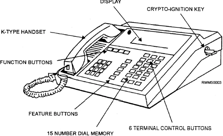
SECURE TELEPHONE UNIT THIRD GENERATION
The Secure Telephone Unit Third Generation (STU-III) is the newest communications system that meets the need for protecting vital and sensitive information over a telephone system. The STU-III is a
compact, self-contained desktop unit capable of providing the user with clear and secure voice and data transmissions. The unit is fully TEMPEST protected and is certified by the National Security Agency for use up to and including Top Secret material.
The STU-III is unique in that it works as an ordinary telephone and as a secure telephone network to other III terminals. For secure transmissions, the STU-III uses a unique keying system.
The three manufacturers of the STU-III terminals for the Navy are AT&T, Motorola, and General Electric. Figure 1-3 shows an AT&T STU-III terminal.
The STU-III is operated the same as any telephone. That is, you pick up the handset, wait for a dial tone, then dial the number of the person you want to call. All calls on the STU-III are always initiated in the clear voice mode. Once the party you have called has answered, you have the option of talking to that person in the clear voice mode, clear data mode, secure voice mode, or the secure data mode.
Terminal Setup
[image:29.623.108.494.471.707.2]The STU-III terminal uses special keys with a designator of KSD-64A. The KSD-64A is a plastic device that resembles an ordinary key. Two types of keys are used with the STU-III, the seed key and the crypto-ignition key (CIK). The seed key is a special keying material used for the initial electronic setup of the terminal. The CIK key is used by the users to activate the secure mode.