MOD 10
MAGNETIC TAPE TRANSPORT
OPERATION & MAINTENANCE MANUAL
200237
JUNE, 1972
~\"ANGCO INCORPORATED 2400 Broadway
PREFACE
This manual has been prepared to pennit separation of the first three sections I which then fonn an operator's manual. Material for these
sections has been scaled to the requirements and training of computer and off-line system operators.
Sections IV and following are addressed to the engineer responsible for setting up and maintaining this equipment on site. Material covered includes:
• Installation of the tape system in system cabinets • Checkout procedures and requirements
• Interconnection of the tape and data systems .. Principles of design and operation
• Module replacement and adjustment.
Users of WANGCO equipment may reproduce this manual to any extent necessary to satisfy their own requirements.
I
REV. LETTERA
B
C
D
E
MOD 10 RI.VISION LEVEL
DESCRIPTION
Original publication To reflect basic product re-design
Update all sections with particular emphasis on Section VI and Appendix B
Update all Sections
Changed pages - Title Page,
iV, IV-3, IV-9, VI-30,
VI-31, VI-34, VI-39, VI-44, VI-47, VI-50, VI-58, VI-59, VI-60, VI-61, updated
drawings to latest revision
iv
DATE
5/70 9/70
10/71
2/72
6/72
SECTION I
SECTION II
SECTION III
SECTION IV
SECTION V
TABLE OF CONTENTS
General Description
1 .
2. 'l
v ~
Purpose Description
System Operation
Operator Maintenance Functions
Installation and Initial Checkout
1
.1. •
2. 3 . 3.1 3.2 3.3 3.4 3.5 3.6 3.7 3.8
Unpacking and Inspection Initial Checkout Procedures Interface Requirements Cabling
Rack Mounting the Transport Input Requirem ents
Input Control Functions Input Data Functions Output Requirements Output Control Functions Output Data Functions
Principles of Operation
1 • 2. 3. 4. 4.1 4.2 4.3 4.4 4.5 4.6 4.7 4.8 5. 5.1 5.2 6. Power Supply
Capstan Drive and Servo System Reel Servo System
Control Electronics
Bring-to-Ready Sequence & System Interlock Brake Logic (Optional)
Reset and On-Line Logic
Motion Logic Forward and Reverse Rewind and Unload Logic
Write Enable Logic File Protect Logic Ready Logic
Data Electronics
Data Electronics, Dual Gap Systems Data Electronics, Single Gap Systems Key to Logic Symbols
SECTION VI Maintenance On Site VI-1
1 . Power Suppl v Maintenance VI-4
1 • 1 Checking Unregulated Power Supply VI-4
1.2 Circuit Breaker Reset VI-4
1.3 Fuses VI-4
1.4 Transformer Taps VI-4
2. OQening of Power SUQQly Assembly VI-6
3. TransQort Module ReQlacement VI-6
4. Data Electronics Module ReQlacement VI-9
~ OCP Switch Replacement VI-9
v ..
6. Arm Sense LamQ and Cell ReQlacement VI-12
6.1 Lamp Replacement VI-12
6.2 Cell Replacement VI-12
7. Head Assembly ReQlacement VI-13
7.1 Replacing the Photosense Unit VI-13
7.2 Cleaning the Tape Cleaner VI-IS
8. Deck Overlay Removal VI-16
8 .. 1 Removal of Fixed Reel VI-16
8.2 Removal of Fixed Guide Post Assemblies VI-16
8.3 Removal of Overlay VI-16
9. CaQstan and CaQstan Motor ReQlacement VI-19
9.1 Capstan Only VI-19
9.2 Capstan Drive As sembly VI-19
9.3 Calculating Capstan Speed Error VI-19
10. Reel Motor ReQlacement VI-20
11. Guide Roller Bearing ReQlacement VI-20
12. TaQe Tracking: Alignment VI-22
12.1 Forward Tape Tracking VI-22
12.2 Reverse Tape Tracking VI-2S
12.3 Checking Tape Tracking VI-28
13. Regulated Power SUQQly Adjustments HT _'>0
VJ.-~.J
14. Arm Sense Module Adjustments VI-30
14.1 Fixed Reel Adjustments VI-30
14.2 File Reel Adjustments VI-30
15. TransQort Module Adjustments VI-31
15.1 EOT/BOT Photosense Adjustment VI-31
15.2 Capstan Servo Adjustment VI-31
15.3 Reel Servo Adjustments VI-33
16. Data Electronics l Dual GaQ Systems
Adjustments VI-35
16.1 Adjustment Sequence VI-35
16.2 Phase Splitter Quiescent Level VI-36
160 3 Read Amplifier Gain VI-37
16.4 Crossfeed Shield VI-38
16.5 Read Strobe Dela
y
VI-3916.6 Read Stack Azimuth Measurement
and Correction VI-41
16.7 Write Stack Deskew VI-43
APPENDIX A
APPENDIX B
1 . 2. 3. 4. 5. 6. ..., I •
B. 9. 10. 11. 12. 13. 14. 15. 16. 17.
lB.
19. 20. 21. 22. 23.17. Data Electronics I Single Gap Systems
17.1 17.2 17.3 17.4 17.5 18. Adjustments Adjustment Sequence Read Amplifier Gain Read Strobe Delay
Head Stack Azimuth Measurement and Correction
Verification--Staircase Measurement
Recommended Spare Parts List
Schematic and Assembly Drawings
LIST OF FIGURES
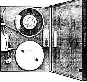
Mod 10 Tape System - Front View
(A) Tape System for Speeds of 25 IPS or Less
(8) Tape System for Speeds of 37.5 and 45 IPS
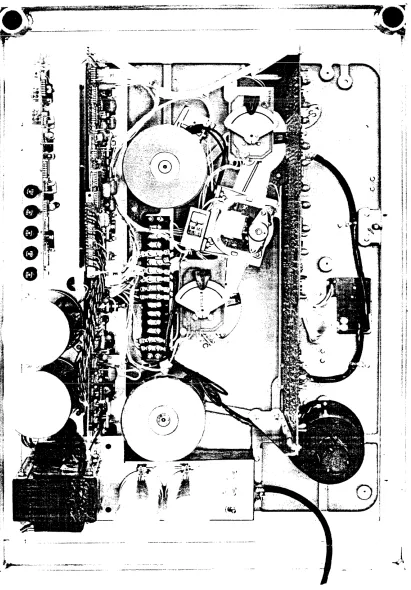
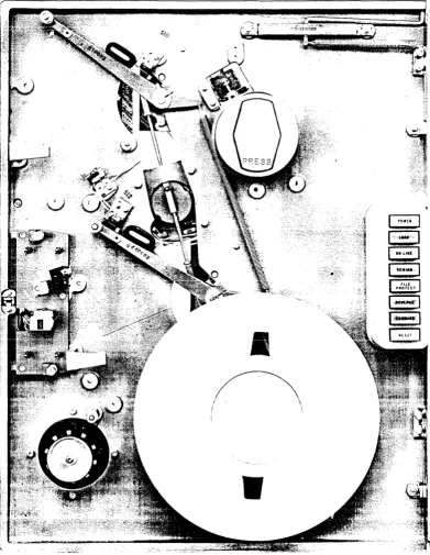
Mod 10 Tape System - Rear View Front View with Overlay Removed
File Reel Mounting Hold-Down Knob in
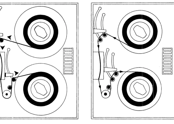
Locked (Top) and Unlocked (Bottom) Positions Tape Threading Path for 25 IPS or Less System (Left)
and 37.5 and 45 IPS System (Right) Operator's Control Panels
Cleaning the Read/'write Head Assembly Cleaning the Roller Guides
Tape System Interface Cable Installation Tape System Rack Mounting
Tape System Installation
Input Termination Configuration Mod 10 Power Supply
Capstan Drive and Servo System
Timing Diagram of Commands to Capstan Servo Reel Servo System
Transport Control Electronics System Interlock Diagram
Flow Diagram of Auto Load Sequence
Simplified Logic of Motion Control (Forward & Reverse) Simplified Logic of Rewind and Unload Control
Simplified Logic of Write Enable Control File Protect Logic
24. 25. '6. 27. 28. ?Q /:JoJ. 30. 32. 33. 34. 35. 36. 37. 38. 39. 40. 41. 42. 43" 44. 15. 46. 47. 48. 49. 50. 51. 52. 53. 54. 55. 56. 57. 58. 59. 60. 61. 62. 63. 64. 65. 66.
i 7 •
68.
69.
Simplified Logic of Ready Control
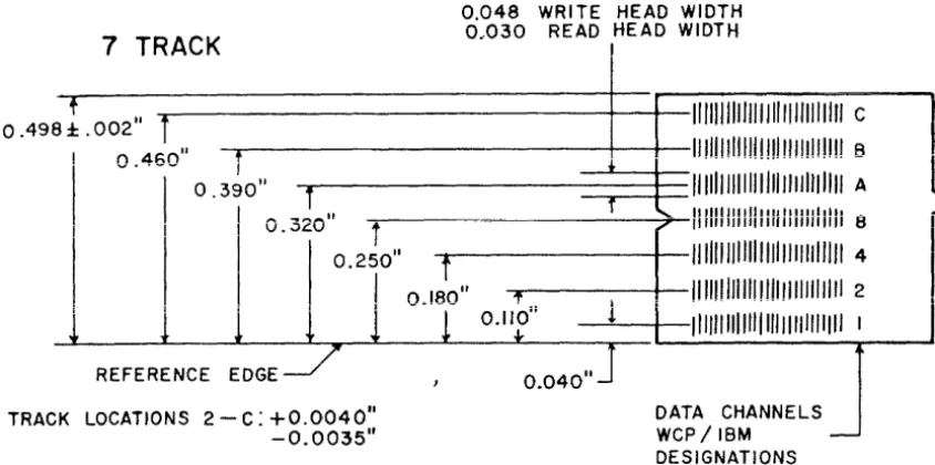
Track Locations and Spacing I 7 -Track System
Track Locations and Spacing I 9-Track System
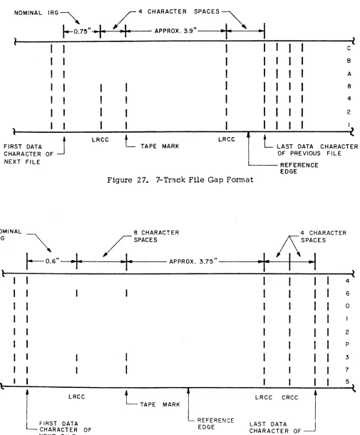
7 -Track File Gap Format 9 -Track File Gap Format
\Afrite Data Flow, Dual Gap Systems
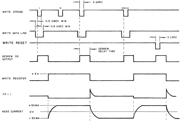
Write Data Flow Timing Diagram, Dual Gap System s Dual Gap Systems
Read Data Flow, Dual Gap Systems
Read Strobe Generation Circuitry, Dual Gap Systems Timing Diagram of Read Data Flow and Strobe
Generation, Dual Gap Systems Write Data Flow, Single Gap Systems
Write Data Flow Timing Diagram, Single Gap System s Write Power Gate and Write Register DC Reset,
Single Gap Systems
Read Data Flow, Single Gap Systems
Timing Diagram of Read Data Flow and Strobe Generation, Single Gap Systems
Read Strobe Generation, Single Gap System s Logic Symbol Example
Mod 10 Power Transformer Lead Identification" How to Open Power Supply
Transport Circuit Module Removal Data Module Removal
Control Panel Switch Removal Head Assembly Removal Fixed Reel Removal Deck Overlay Removal Guide Bearing Replacement Tape Guide Diagram
File Reel Arm Guide Alignment
Tilt Adjustment - File Reel Arm Guide File Reel Fixed Guide Adjustment
Checking Tape Tracking, Desired Waveforms Stop Ramp Time
Read Amplifier Gain Adjustment, Dual Gap Systems Head Gate Adjustment, Dual Gap Systems
Head Gate Adjustment Waveforms I Dual Gap Systems
Read Strobe Delay Adjustment, Dual Gap Systems Head Stack Shimming, Dual Gap Systems
Triggering Method
Staircase Waveform, Dual Gap Systems
Read Amplifier Gain Adjustment, Single Gap Systems Read Strobe Delay Adjustment, Single Gap System s Head Stack Shimming, Single Gap System s
Staircase Waveform I Single Gap Systems
MOD 10 Tape System - Rear View Front View with Overlay Removed
LIST OF TABLES
1 . Mod 10 Specifications 1-3
2 . Input/Output Pin Assignments IV-9
3. Logic Symbols V-45
4. Maintenance Tools and Supplies VI-2
5 . Suggested Schedule for Preventive Maintenance VI-3
6. Data Electronics Adjustment Points I Dual Gap Systems VI-38
7 • Data Electronics Adjustment Points I Single Gap Systems VI-49
1 .
2.
SECTION I
GENERAL DESCRIPTION
This manual describes the operation and maintenance of the
WANGCO Mod 10 digital magnetic tape transport system.
PURPOSE
The system provides the equipment necessary to:
A. Move half-inch magnetic tape across a read-write head in response to commands from remote equipment or to signals generated from the operator's control panel located on the transport;
B. Read or write data on magnetic tape and transfer this data between the transport and the controller.
DESCRIPTION
The Mod 10 is shown in Figures 1 - 3 of this section.
In a computer or other data processing system I the magnetic tape
units are used to store very large amounts of data. Recovery of the data without errors depends on proper installation and maintenance of the tape units and the tape itself. The Mod 10 has been designed to permit easy operation and simple maintenance; it also has ample safeguards to protect the tape from damage during its use with the tape unit.
In its standard versions I the Mod 10 uses half-inch computer-grade
tape I on reels up to I 0 -1/2 inches in diameter. The file or supply
reel mounts on a hold -down knob that is the same size as the knobs on IBM units. Data on the tape is written so that it may be read
by IBM systems; tapes written with IBM equipment may also be read on the Mod 10. Seven or nine tracks of data are written on the tape at densities of 200 I 556, 800 I or 1600 characters per
inch. In the Mod 10, two NRZI densities are provided in the following combinations of the three standard fonnats: 200 and 556, 556 and 800, 200 and 800 for the seven-track fonnat, and 800 for the nine-track fonnat. When data is written on tape at a density of 1600 characters per inch, it is phase encoded and onJy t..he single density is provided in the system =
Tape speeds that are standard to the Mod 10 are 10 , 12.5, 18.75, 25, 37.5 and 45 inches per second. With all the com-binations of tape speed and data densities considered, data may be transferred into or out of the tape system at rates from 2000 to 72,000 characters per second.
During nonnal operation of the tape unit with the data system, tape motion and the reading or writing of data are controlled by the
system. When the tape system is not under computer control (i. e. , when it is off line), tape motion can be controlled by the operator through pushbuttons on the front of the m<;lchine. Indicator lights are also provided to show the conditions under which the equipment is operating. Complete details about these functions a nd indications are provided in Section II.
When the system is operating I the speed and direction of the tape
are determined by the capstan. As it turns I the capstan pulls the
tape past the head assembly so that it may be either written or read. For the tape system to operate efficiently I the tape must be
started and brought up to speed as quickly as possible. The \¥eight of the tape on the reels prevents the reels from starting as rapidly as the capstan, so a small length of tape is held by buffer arms near the supply and takeup reels. When the capstan starts quickly, the buffer arms are either pulled in or released by the tape motion. Changes in the position of these anns result in the supply and takeup reels either feeding tape to the capstan or taking up the slack created by the capstan motion.
Reflective markers at either end of the tape prevent it from being pulled completely from either the supply or takeup reels, except when the operator wants to change the reel. A sensing post near the read/write head assembly illuminates the tape and issues a stop signal when the marker reflects the light into a photocell. Markers for the beginning and end of the tape are' on opposite sides I providing
to the computer or data system an indication of which end of the tape has been reached.
To provide the greatest assur~nce that data on the tape will be read
correctly I the tape is cleaned just before it gets to the head assembly.
The tape cleaner has small holes into which loose dirt or oxide is de-posited as the tape is drawn across the cleaner. For best system
oper-ation, the dirt must be removed from the cleaner periodically I as
described in Section III for the important operator maintenance functions of head assembly and tape guide cleaning.
SPECIFICATIONS
Transport specifications are listed in Table 1.
Table 1. Mod 10 Specifications
Data Density:
Tape Velocity:
Rewind Speed:
Total Speed Variation:
Start/Stop Distance:
Start/Stop Time:
Head:
Number of Tracks:
Recording Mode:
1-3
9-track--800 cpi I 1600 cpi
7-track--800/556, 556/200, 800/200 cpi
10,12.5,18.75,25,37.5,45 ips
150 ips Nominal
±.
4% maximumstart distance
= •
17 ±. .02 in.stop distance
= •
19±.
.02 in •.37.5
±.
2.5 millisec at 10 ips30.0
±.
2.0 millisec at 12.5 ips20.0
±.
1.3 millisec at 18.75 ips15.0
±.
1.0 millisec at 25 ips10 .0
±.
O. 7 millisec at 37. 5 ips8. 3
±.
0 • 6 millisec at 45 ipsdual gap or single gap
7 IBM -compatible 9 USASCII -compatible
Table 1. Mod 10 Specifications, cont'd. Static Skew I WRITE:
Static Skew I READ:
Dynamic Skew: Tape Specifications:
Reel Size:
Tape Tension: Electronics:
Tape Unit Interface: Weight:
Height: Width: Depth: Power:
Operating Environment
Temperature:
Relati ve Humidity:
Non-Operating Environment
Temperature:
Relative Humidity:
Altitude:
I - 4
electronic skew compensation supplied on dual gap units 100 micro- inches, maximum 75 micro-inches I maximum
computer grade I O. 5" wide, 1. 5 mil
thick Mylar base
up to 10. 5-inch diameter, IBM hub compatible
8 • 0
±.
a •
5 oz.silicon solid state and 930 series DTL logic
DTL logic (l0V! true)
100 lbs. 24" 19 11
1111 (from mounting surface) 110-125 VAC
±.
10 %,2.3 amps/220-250VAC
±.
10%, 1.2 amps, 4S-60Hz20 - SO %, non -:condensing
15 - 95 %, non-condensing
(A) Tape System for Speeds of 25 IPS or Less
(B) Tape System for Speeds of 37 • 5 and 45 IPS
Figure 1. Mod 10 Tape System - Front View
[image:14.612.169.475.44.331.2]:
..
I
~--'""'
.."
...j
Figure 2. MOD 10 Tape System - Rear View
[image:15.612.93.504.96.686.2]!
I
~
I \
•
Figure 3. Front View with Overlay Removed
[image:16.613.133.524.171.676.2]SECTION II SYSTEM OPERATION
Operation of the Mod 10 tape system requires only a few simple pro-cedures. These include tape loading and unloading I manual rewind I
power failure recovery I and possible other special operations required
by the data processing system using the tape equipment.
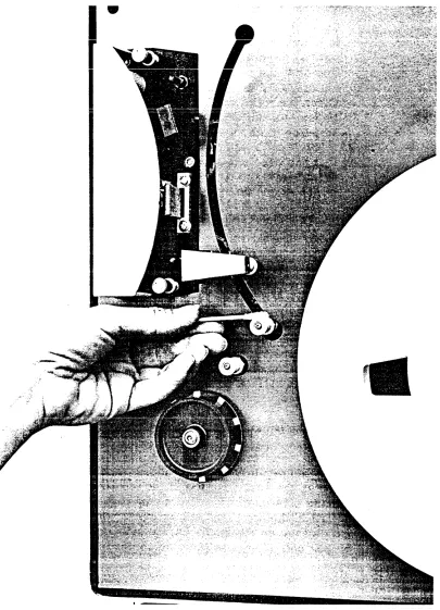
TAPE LOADING is made particularly easy by the toggle-action hold-down knob (Figure 4 ) designed for the Mod 10. Positive indication is provided by the knob for installation of the reel and for the locked condition. To prepare the knob for installation of the reel, depress the toggle at the enp marked PRESS. It will remain in that position. Place the tape reel on the knob I with the write enable ring I or the
slot provided for it, toward the tape unit. This will automatically position L~e end of the tape on the reel for proper threading. After pressing the reel firmly against the knob I using the fingertips against
the REEL HUB ONLY, pres s the extended end of the toggle tab until it is flush with the face of the hold -down knob. The snap action of the knob will be distinctly felt, and the knob is then firmly locked. It is not necessary to hold the reel against the knob when the knob is being locked. Care should also be taken to avoid pressing the reel flanges against the tape pack when loading the tape or locking the knob. Pressure of the flange against the tape edges causes two types of damage: oxide is dislodged from the film I causing potential read
errors; deformity of the edge of the tape results in misalignment of the tape as it passes the head I with an increased possibility of errors.
To thread tape on 10 I 12.5 I 18.75 or 25 ips Mod 10 systems (Figure 5) I
follow this procedure:
"
f
\
I
\
[image:18.612.68.519.30.693.2]/
.
figure 4. Flle Reel !v1oulJ.ting Hold-Down Knob in
:"ocked (Top) anu "t; nlocked (BaHam) Positions
-
I" I 1\\-w III I I \\ ... /
c::::J
~~'
c:=:J
c::=::J
t:=]
.,....---...
It:=] c=:J c=:J'\ .. 1c::==J
Figure 5. Tape Threading Path for 25 IPS or Less System (Left) and 37 • 5 and 45 IPS System (Right)
~~
'-c::::::J
c:::::J c:::::J
c:::::::::J c::::::J
c=:J
c:=::J
[image:19.794.107.706.82.508.2]1 • Lead the end of the tape over the buffer ann guide and down through the slot guide in the head assembly cover. The passage of the tape through the slot causes the small shield over the head assembly to move away from the head. The tape then tracks properiy over the read/write heads and other elements in the head assembly. 2. At the capstan end of the head cover slot, lead the tape
around the capstan and over the top of the other buffer guide.
3. Pass the tape over the top of the fixed takeup reel, 4. Press the end of the tape against the hub through one
of the openings in the reel flange.
5. Holding the tape against the hub, turn the reel until the end of the tape is overlapped and secured by the next tape layer.
6. By hand, wind three full turns of tap~ onto the takeup reel. 7. To complete the loading operation, firmly press the LOAD
pushbutton on the operator's control panel (Figure 6). Both buffer ann s will move to their nonnal operating positions and the capstan will pull the tape forward until the beginning-of-tape (BOT) marker reaches the photosense assembly. Control of the tape system will then be turned over to the data system tape controller automatically; and the ON-LINE indicator and LO.lI~D indi-cator will light up. No operator action is needed to put the tape system on line.
8. If the on-line mode is not desired I the tape unit may be
taken off line, for control from the operator's control panel, by pressing the RESET pushbutton.
To thread tape on 37.5 ips or 45 ips Mod 10 systems (Figure 5), follow the previously described procedure for 25 ips units, except that the tape must be led across both rollers of each buffer arm guide assembly.
At the conclusion of a tape system operation with the computer I or at
other times when it is necessary I the tape will be rewound onto the
supply reel. Normally I the computer or data system will issue a
re-wind command without operator participation. Other conditions will sometimes require the operator to rewind the tape by pressing the REVVIND pushbutton on the operator control panel. This will result in high-speed reverse operation. When the beginning-of-tape marker
reaches the photosense unit I the rewind will be ended j and the tape
unit will advance the tape until the reflective marker is at the photo-sense head.
TO UNLOAD THE TAPE I push the REWIND pushbutton again. The tape
will be pulled through the tape path and returned to the supply reel. The tape reel may then be removed from the machine by pressing the
knob toggle to the unlocked position. Again I care should be taken to
avoid damage caused by pressing the reel flanges against the sides of the tape.
In the event of power failure while the system is on line, the buffer
arm s will extend and tension on the tape will be relaxed I preventing
any possible tape damage. When power has been restored I tape system
operations may be resumed by first taking up the tape slack and then pressing the LOAD pushbutton. When the buffer arms have returned to their operating positions, pres s the RESET pushbutton to stop tape
motion. Then pres s the REWIND or ON-LINE pushbutton I depending
on the requirements, of the system with which the Mod 10 is operating.
In the following list, the other operator control functions and indicators
(Figure 6) are described I v.Jit...~ a revieVI of those already mentioned:
r ~ r ~ r :"'
I[POWER
II
POWER~
II POWERJI
""'"j
...
lO C
-;
(!)
II
LOADII
LOADI
[ LOADen
0
lioN LINE
I
ION LINEI liON LI NE'0
(!) -;
1-4 OJ
1-4 r-t'
0
~
REWINDI
I
REWIND~
II
REWINDI
-;
-en til
() 0
Ii
ptciffcTj
II
PROTECT FI LEj
II
PROTEC FILE~
::J
q
0
-"'0
[REVERSE~
II
DENSITYI
~ORWARDII
OJ
::J
(!)
-tilI[FORWARD
I
IIFORWAR~
[ RESET III
RESETI
I
RESETI
[UNIT
SELECTII
\. J \.. :J \.. :I
r PO\VER
LOAD
ON LINE
FILE PROTECT
REWIND
This is a combination pushbutton switch and indicator ~ The indicator is on when regulated power has been supplied to the Mod 10. For the convenience of the maintenance or customer engineer ,. a power switch is provided on the power supply chassis at the rear of t..l}e machine.
It is acces sible only when the tape unit is swung open for service.
After threading the tape, press this combination pushbutton switch and indica tor to complete the tape loading operation. Tape is automatically advanced to the load point, or beginning-of-tape marker I and then the tape system goes on line.
LOAD and ON LINE will be lit when the action is completed. The LOAD light will go out when the tape is advanced from the load point or rewound. The LOAD light will be lit any time that the tape is positioned at the load point. After this sequence of opera tions is completed the switch becomes functionally disabled and can only be re-enabled by loss of tape tension.
This is a combination pushbutton switch and
indicator. As previously mentioned I it is lit when
the system is under control of the computer or data system. If the system is off line and if con-trol is to be turned over to the com~uter, press the ON-LINE pushbutton. The system will be returned to the OFF-LINE mode if the system inter-locks are lost, an OFF-LINE controller command is sensed I or the RESET pushbutton is depressed.
This is an indicator that is let when a write enable ring is not installed on the file reel. When a supply reel is put on the machine with the write enable ring in place in the slot at the back of the reel, the FILE PROTECT light will be off. This indicates that data may be written on the tape. With the ring in place I
protective circuits in the tape system prevent data from being written on the tape.
Pres sing this pushbutton switch will result in rewind of the tape at high speed. The operator can stop this reverse motion by pressing the RESET pushbutton. If
REWIND (cont'd. )
FORWARD
REVERSE
RESET
RESET/UNIT SELECT
RESET is not pressed I the tape will go beyond
the beginning-of-tape marker, stop, and then automatically return to the load point. If the REWIND pushbutton is then again pressed, the tape wiil be drawn out of the tape path and the unload sequence will be completed. If the tape system is under computer control, the REWIND pushbutton is disabled. This safety feature pre-vents accidental tape damage.
This is a combination pushbutton switch and indicator. The pushbutton will function only when the rrachine is off line. If the ON-LINE indicator is on, pressing the FORWARD push-button will have no effect. If the ON-LINE indicator is off and the FORWARD pushbutton is pressed, the indicator will light up and the tape unit will move tape in t he forward direction at the normal tape speed. To stop the machine, when it is running in this mode, pres s the RESET pushbutton.
If the ON-LINE indicator is on, the REVERSE pushbutton is disabled. If the tape unit is off line, pressing this combination pushbutton switch and indicator will light the light and move the tape in reverse at the normal tape speed. To stop the machine when it is running in this mode, pres s the RESET pushbutton.
This switch is used only on NRZI units. All tape motion, except UNLOAD I will stop when the RESET
pushbutton is pressed. Pressing RESET clears all read, write and control functions. It also removes the tape unit from on-line operation with the computer or data system and turns off the ON-LINE indicator. This switch is used only on all Phase Encoding units and replaces the normal RESET switch described above. This switch performs all the functions of the RESET switch but in addition, it houses the UNIT SELECT INDICATOR. This indicator is illuminated if the unit has been selected. See Figure 6-D.
UNIT SELECT
DENSITY SELECT
This switch is standard on all Phase Encoding units and optional on NRZI units. When this switch is used I the REVERSE switch is not
installed. This is a 4-position switch used to make the transport assignment in a daisy chain configuration. A particular drive in the daisy chain is automatically selected if the switch
identification number corresponds to the controller select line which has been conditioned TRUE. See Figures 6-C and 6-D.
This alternate action switch is optional for NRZI units. When it is used I the REVERSE switch is
not installed. When depressed to select High Density I it conditions the data electronics to
operate at the high data transfer rate and also causes the indicator to light. When the switch is again depressed, the lower data rate capability is selected and the light is extinguished. See Figure 6-8.
SECTION III
OPERATOR MAINTENANCE FUNCTIONS
Proper and regular maintenance of the Mod 10 tape handler will assure operation at the high levels of data and mechanical reliability that have been designed into the system. Particularly important are the operator maintenance functions that are intended to keep the system free of dirt and contaminants. At the high densities of data on tapes written or read with the Mod 10, extremely small particles of dust or oxide from the tape are capable of causing data errors. Careful attention to the cleaning procedures described in this section will assure the greatest possibility of trouble-free operation.
TRANSPORT AND HEAD CLEANING should be performed after every eight hours of system use. Following are the steps to be carried out:
1. Remove tape from the tape unit I as described in Section II.
2. Remove the head covers by pulling both pieces, one at a time, directly away from the front of the machine. The covers will come off with a gentle, steady pull.
3. Moisten a soft, lint-free cloth or Q-tip applicator with isopropyl alcohol. After the head surfaces, including the surface of the erase head, have been carefully swabbed, they should be dried with a separate clean and lint-free cloth. Sep Figure 7.
FigLre 7. :=::e~::-,ing ~r-:e Rcad.\'/rite Head Assembly
4. Clean the face of the tape cleaner I following the
same procedure described in step 3.
5. Clean the head g~ides and head guide blocks I shown
in Figure 7. The guide blocks are immediately in
back of the guides. Dry all parts with a clean,
lint-free cloth.
6. Clean the rolier guides (Figure 8 ) , rotating them to be sure all surfaces are cleaned. Dry with a clean, lint-free cloth.
7 • If it has been removed, replace head cover by aligning the holes in the cover with the mounting pins on the transport and pressing finnly into place.
CAPSTAN CLEANING should be perfonned after every eight hours of use I
following this procedure:
1 . Moisten a cloth with water.
2. Rotate the capstan slowly with one hand, without touching the rubber surface.
3. At the same time I clean the surface of the capstan with
the moistened cloth. Make a visual inspection of the capstan surface for abrasion or polish; if defects are observed I contact the maintenance engineer.
4. Dry the capstan with a separate clean and lint-free cloth.
Additional cleaning requirements are carried out at longer intervals. Every four months the entire surface of the tape unit should be cleaned, making sure that accumulations of dust around the hold-down knobs and in the head area are removed. Head covers should be removed and cleaned on the inside and outside I making sure that all
deposits of dust and other possible tape contaminants are removed. Any periodic maintenance functions beyond those described here are suggested for perfonnance by customer f' .. gineers. Details of these
additional procedures are described in Section VI.
Figure 8. Clc-; :-d:-lg the Roller Guides
[image:29.612.92.497.95.656.2]1 .
2.
SECTION N
INSTALLATION AND INITIAL CHECKOUT
This section provides installation instructions for the Mod 10 magnetic tape system. Infonnation on unpacking the system and on the procedure for electrically connecting and checking out the system is included. UNPACKING AND INSPECTION
Inspect the shipping container for evidence of in-transit damage. Contact the carrier and manufacturer if damage is evident. Specify nature and extent of damage ..
Open shipping container and remove contents. Check items removed from the shipping list to verify container contents. Contact a company representative in the event of a packing shortage ..
Remove protective padding and covering from the tape system. Verify that the serial number of the unit corresponds to that shown on the shipping invoice.
Visually inspect the exterior of the enclosure for evidence of physical damage that may have occurred in transit.
Check major component assemblies to detennine if any assemblies or screws have been loosened. Tighten any loose screws or mounting hardware. Inspect input/output connectors.
INITIAL CHECKOUT PROCEDURES
To check the proper operation of the transport before placing it in the system I follow the specified procedure ..
3.
1. For applications not employing 115 VAC line power I
verify that the appropriate primary power transfonner
wiring is correct. This can be accomplished by
swinging out the power supply chassis and checking the wiring against the voltage decal mounted on the deck of the transport. See Figure 43.
2 . Turn the transport power on by setting the power switch located on the power supply chassis to the ON position and pressing the POWER pushbutton switch located on the operator's control panel. At this point the POWER indicator should light up.
3. Load tape on the transport as described in Section II. 4. Press the LOAD pushbutton to initiate the load sequence.
The tape will move forward until it reache s the BOT tab. The ON-LINE indicator should light when the BOT reaches the photosensor. At this point I there
will be no action when the LOAD pushbutton is pressed. To remove the system.from the on-line mode I pres s the RESET pushbutton. The system is
now in the off-line mode.
5 . With the transport off line (ON LINE indicator not illuminated) I press the FORWARD pushbutton. Run
several feet of tape onto the takeup reel and pres s the RESET pushbutton to stop the tape. Be sure that when the transport is on line I the action of the FORWARD
pushbutton is inoperative c
6.
7
,
.
Press the REVERSE pushbutton. Tape will move backward until the BOT tab reaches the photosensor. Be sure that the action of the control is inoperative when the transport is on line.
Using the FORVIARD pushbutton, run several feet of tape onto the takeup reel. Pres s the REWIND pushbutton to initiate the rewind mode. The tape will rewind pa st the BOT tab, return to the BOT tab, and stop with the LOAD indicator lit. If the REWIND pushbutton is now pressed, the tape will rewind until tape tension is lost. This action is used to unload tape. The reel can be removed as outlined in"Section II.
INTERFACE REQUIREMENTS
The interface for NRZI only is given in this section. Phase Encoding interface information will be incorporated in a special Addendum.
3.1
3 .. 2
3.3
CABLING
The interface cables shall be twisted pairs with returns grounded.
Wire shall be #24 or #26 AWG conductor with minimum insulation
thickness. Cable twist sl1.all be approvimately 30 twists per foot.
Maximum cable length shall be 20 feet. The ground side of each
pair shall tenninate within a few inches of the line receiver or
transmitter ground. Connectors shall be Transitron 600-061-18-SL or equivalent. Cables should be vv"ired and strain relieved as shovvn
on Figure 9.
RACK MOUNTING THE TRANSPORT
The transport may be mounted in a standard 19 inch RETMA or Universal
rack with a minimum panel space of 24 inches. A depth of 11 inches
minimum is required behind the rack mounting surface. The procedure
for mounting (see Figures 10 & 11) is as follows:
1 • Remove safety blocks from below hinge s then
lift transport off shipping frame.
2 • Remove hinge-half off shipping frame and install
same on rack in desired position.
3 . Hang transport on rack and lock in the closed
position by tightening catch screw in front of
the dE?ck.
4. Replace safety blocks.
INPUT REQUIREMENTS
Input voltage requirements I a diagram of input load configuration,
and a list of input control and data functions are shown below:
Input Requirements
FALSE (Logic 0) + 2 • 5 to + 5 • 5 v
TRUE (Logic 1) 0.0 to +0.5 v
CONTROL
J16~
INPUTS \
\
"Figure 9. Tape System Interface Cable Installation
IV - 4
J6
READ DATA
r---
19.00I
Figure 10.. Tape System Rack Mounting
N - 5
1,91,
~ SAFETY BLoeM
~~
~i
\
:15.750
-
.---
..-.--... .J
___ .J
..
...---
..r·...-1 r·...-1 - . ~_ NO. 10 WASHER
,.~~--~~ e~~...----NO. 10 SCREW
Fitgure 11. Tape System Installation
A
+5V
SIGNAL - SiGNALn---.... ---4~
GRD o - - - r - - - . GRD ~-... - _ .
p P
INTERNAL - SINGLE TAPE UNIT EXTERNAL- MULTIPLE TAPE UNIT
Figure 12. Input Termination Configuration
Input Functions
Input Control Lines Input Data Lines
Select (1 Line) Write Data (7 or 9 Lines) Unit Select (4 Lines) Write Data Strobe (1 Line) (Option)
Write Reset (1 Line) Forward/Reverse (1 Line)
Read Permit (1 Line) Run/Stop (1 Line)
Write Permit (1 Line)
Rewind (1 Line)
Low Read Threshold
Density Select (1 Line) Select* (l Line) Off-line* (1 Line)
*these functions are not required for proper operation; therefore I they
may be left disconnected.
3.4 3.4.1
3.4.2
3.4.3
3.4.4
3.4.5
3.4.6
The following on-line input signals (sections 3.4 and 3 .. 5) con-trol operation of the Mod 10 tape transport only after power is on, the on-line mode has been initiated, ready status has been established, and the unit has been selected. (Table 2 shows the pin connections required to achieve correct interface with the tape controller.)
INPUT CONTROL FUNCTIONS
Select (I Line). When this becomes TRUE, it enables all the write and read circuitry, the on-line transport control commands, and the status output lines if the ready status line is TRUE and if
the unit is in the on-line mode. When the level goes FALSE, the above transport functions are disabled.
Unit Select (option - 4 Lines). Four Select lines are provided such that when the one which is TRUE corresponds to the unit select switch position, the unit will be selected.
Forward/Reverse (1 Line). The state of this line will detennine the direction of tape motion upon receipt Qf a run command. When TRUE I the unit will be conditioned for forward motion. When
FALSE I it will be conditioned for reverse motion. A transition
shall not occur on this line while the Run/Stop signal is TRUE I
but may occur simultaneously to a change on it.
Run/Stop (l Line). A TRUE level on this line will cause tape motion in the direction conditioned by the Forward/Reverse line. A FALSE level on this line will stop tape motion.
Rewind (l Line). A 2 J.t sec minimum pulse on this line shall cause
the tape transport to drive tape I at 150 ips, in the reverse
direc-tion and stop at the Load Point I illuminating the Load Indicator.
The transport will remain in the On-Line mode. If already at Load Point when the rewind command is given, the command will be ignored. All other motion commands are inhibited until the rewinding sequence is complete.
Densi ty Select (l Line). A TRUE level on this line conditions the MTT to operate at the higher packing density. A FALSE level selects the lower data packing density. This line is internally tied TRUE for 9-track systems.. This line is inoperative when the Density Switch option is used.
N - 8
Table 2. Input/Output Pin Assignments
Connector
#
ELCO-00-600 7 -036-980 -00 2 Signal Nomenclature Signal Pin Ground Pin (or equivalent)
I-I6 rSELECT 0
1
I/
SELECT I ('\1'"'\+; ... 8
I
I
SELECT 2J
'-JtJ"'.LV1!
7
I
CONTROL SELECT 3 9
•
INPUTSj
SELECT J 8I
I
FROM FORWARD/REVERSE C 3CUSTOMER '" ... RTTN
__
.. ; /~1'np--_
.. E 51
REWIND H 7OFF-LINE L 10
DENSITY SELECT D
/
4,; READY STATUS T_V! 16
ON-LINE STATUS M II
STATUS REWiN'IJffiG STATUS N 12
OUTPUTS EOT STATUS U 17
TO .. BOT STATUS R 14
I
CUSTOMER WRITE ENABLE STATUS P 13
HI/LO DENSITY STATUS F 6
...
' .. +5 v. TERMINATOR
POWER (Option) S
I-I WRITE WRITE PERMIT B 2
I
DATA READ PERMIT E 5 I
INPUT LOW READ THRESHOLD D 4
I
CONNECTOR WRITE DATA STROBE A I
WRITE RESET C 3
WRITE DATA PARITY L 10
WRITE DATA 0 M II
WRITE DATA 1 N 12
WRITE DATA 2 P 13
WRITE DATA 3 R 14
WRITE DATA 4 S IS
WRITE DATA 5 T 16
WRITE DATA 6 U 17
WRITE DATA 7 V 18
+5 v. TERMINATOR
POWER (Option) K
I-6
READ READ STROBE 2 BI
DATA READ DATA PARITY 1 A
OUTPUT READ DATA 0 3 C
CONNECTOR READ DATA 1 4 D
READ DATA 2 8 I
READ DATA 3 9 K
READ DATA 4 14 R
READ DATA 5 15 S
READ DATA 6 17 U
I
READ DATA 7 18 VI
3.4.7
3.5.1
3.5.2
3.5.3
3.5 .. 4
Off-Line (l Line). This is a level or a 2 J.l sec minimum pulse
which resets the On-Line flip-flop to the ZERO state I placing
the transport under manual control. It is gated only by Select in the transport logic I allowing an Off-Line command to be
_.! _ _ _ _ _ _ _ 1-.:1.- _ n __ .... .:_~ :_ ..! _ _ _ _ _ _ _ _ _
y~V(;:!l1 VVJ.U~(;:! a ~~VV~UU J.~ J.U .iJ.Luy.L~~~.
T .... TT"\TTrn T-..l\ rnl\ ,..,TT .... T,-..rnT"'II.Tn .11\1 J:'" U.L lJR.LR r U l\1\.J .L.LVl'\1':>
Write Data (9 or 7 Lines). One line is required for each bit in a character. The write data lines establish the controlling con-dition for the NRZI write register. When TRUE I the state of the
corresponding flip-flop will be changed at the time of the write data strobe. This will change the direction of the current through the write head and establish a flux reversal (ONE) on the tape. When FALSE I the state of the flip-flop will not be changed at the
time of the write data strobe. This will result in no change in the direction of write head current, hence no flux reversal (ZERO) will be on tape. These data lines must be held steady through the time interval from
o.
5 ~sec before to 0.5 f.tsec after the write data strobe. A minimum of one data line must be TRUE for everystrobe.
Write Data Strobe (1 Line). A 2 f.t sec pulse on this line causes
a change in the state of any NRZI write register cell for which the corresponding write data line is TRUE. One pulse is required for each character to be recorded. The recording density is de-termined by the tape speed and the frequency of the pUlses. The frequency will be stable within O. 25 per cent.
Write Reset (l Line). A 2 ~ sec pulse on this line resets the NRZI write register. This pulse is used to write the longitudinal parity check (LPC) character at the end of each block of data I
creating an even number of flux reversals (ONE I s) in each track
of the block.
In a seven-track system I this pulse occurs four character times
after the last write data strobe of every block of data.
In a nine-track system I this pulse occurs eight character times
after the last write data strobe of every block of data.
Read Permit (l Line).. The read permit line is used to enable all the read circuitry. When this line goes FALSE I the strobe generator
is disabled and the read register "is DC reset. This line can be tied permanent! y TRUE.
IV - 10
3.5.5
3.5.6
3.6
Write Permit (1 Line). When a write enable ring is on the file reel and write permit is TRUE I the tape transport is placed in
the write mode.
Low Read Threshold Select (l Line). A TRUE level on this line selects a low threshold level (12 per cent) for the read signals. allowing for the detection of marginal areas of tape. A FALSE level on this line selects the normal read signal tp..reshold level
(25 per cent). This line is active only in the read mode on dual gap machines since the threshold level in the write mode is fixed at 45 per cent.
OUTPUT REQUIREMENTS
Output requirements I output current levels I and a list of output
control and data functions are displayed below. Output Requirements
FALSE (Logic 0) User term ina te s line as shown in Fig. 12-A. TRUE (Logic 1)
o •
0 to +0. 5 v.Output Current Level
FALSE Level Open Collector
TRUE Level 40 milliamp max. sink
I
I
.
3.7 3.7.1
3.7.2
3.7.3
3.7.4
3.7.5
3.7.6
Output Functions
Output Control Status Lines Output Data Lines
Ready Status (1 line Read Data (7 or 9 lines)
On-Line Status
..
Read Strobe (l line)I
Rewinding Status
..
I
EOT Status
..
BOT Status
..
Write Enable Status
..
Hi/Low Density Status (..
)The following on-line output signals (sections 3. 7 and 3.8) provide the data functions when the unit is ready and selected. The Control Status functions are activated when on-line- and selected. (Refer to Table 2 for pin connections.)
OUTPUT CONTROL FUNCTIONS
Ready Status (l Line). This line is TRUE when 't.~e transport interlocks are made and the unit is on-line.
On-Line Status (l Line). When TRUE I this line indicates that
the on-line flip-flop is set and the transport is under remote control.
Rewinding Status (1 Line). When TRUE I this line indicates that
the tape transport is rewinding. The rewinding function is com-pleted when the tape stops at the Load Point.
EOT Status (l Line). When TRUE I this line indicates that the
tape transport is sensing the EOT reflective marker.
BOT Status (l Line). When TRUE I this line indicates that the
tape transport is sensing the BOT reflective marker.
Write Enable Status (1 Line). ~ TRUE level on this line indicates that a write enable ring has been installed on the supply reel.
IV - 12
A
Hi/LovV' Density Status (l Line). Vv'hen this line is TRUE, the
transport has been set for low-density operation I and the read
circuitry has been conditioned accordingly. This line is used
only for seven-channel ~ystems.
3.8 OUTPUT DATA FUNCTIONS
3.8.1
3.8.2
Read Data (9 or 7 Lines). One for each bit in a character. The
data is in the forrr! of pulses OCCliI!-ing sirllultar1eously and
coin-cident with the Read Strobe pulse. The presence of a pulse indi-cates a ONE and the absence of a pulse indiindi-cates a ZERO. These pulses shall be 2 usec wide.
Read Strobe Pulse (1 Line). The Read Strobe line shall provide a pulse of 2 usec for each data character read from tape. This pulse shall be coincident with the data pulses.
1.
SECTION V
PRINCIPLES OF OPERATION
For best understanding of the principles of operation of the Mod 10 tape system, the major subassemblies are described separately. The functional separation of system operations relates conveniently to the actual physical packaging of the subassemblies. Following are the major subassemblies, in the sequence in which their operation is explained:
1 . Power supply
2. CapstCin drive and servo system 3. Reel drive and servo systems 4. Control electronics
5. Data electronics POWER SUPPLY
A single assembly supplies power to the entire system I handling the
needs of the capstan and reel drive system s I the data electronics and
the option electronics. As shown in Figure 13, AC power to the system is controlled by a double-pole, single-throw switch on the power supply chassis and by a single-pole I single-throw pushbutton switch on the
operator's control panel. The switch on the power supply chassis must be switched on to use the operator's control panel switch to control
power. A three-wire cord is used with the ground line connected directly to the power supply chassis. A circuit breaker is provided in the hot s ide of the primary power line.
<
N
LINE,
VOLTAGE
DPST SWITCH
~ I
I I
125V
- ~---.---~~~
...-v- 0
GND
.~
TI
GND
i
I
+ 19V
+
FI 5A
TO SERVOS
~~ +I~~ V REG.
330 f\.
3W
'----t--1:2V REG.
1"\...-. . . - - - -... TO SERVOS
-19V F2
lOA
330 J\. + 100,000 j.1F
I"\.. _ _ _ _ _ _ _+_ TO SERVOS
r
+5V REG.
~"_4~_3--W
__-~---.---~~
330 J\. + 100,000 jJF
3 W 20V F5
lOA
-I~-"""TO SEI~VOS
L _____ ~ _____ . _
Unregulated DC from the power supply is sent to the regulators, which are on a separate printed circuit board mounted to the power supply chassis; this DC is also used to drive the capstan and reel motors. Voltages supplied unregulated are +19 volts, -19 volts, +]3 volts, and -12, and +5 voltages.
Each voltage regulator consists of a linear integrated circuit amplifier plus power output transistors. The output voltage tolerance for the regulators is ±5 per cent and each is potentiometer adjustable. The + 12 and -12 volt regulators can supply up to 1.5 amperes and the +5 volt regulator, up to 3.5 amperes.
The output level of the +5 volt regulator is prevented from rising above +8 volts to protect the integrated circuits used in the system from over-voltage stress that could occur under abnormal conditions. If the over-voltage on the +5 volt line goes above +8 volts, an SCR will conduct, shorting the + 13 volt unregulated input line to ground until the fuse opens, thus protecting the circuits.
2. CAPSTAN DRIVE AND SERVO SYSTEM
All tape motion in the Mod 10 is initiated by the capstan, which is driven by a DC motor. Wnen the motor is running, a tachometer
generates a DC voltage that is used to control the tape velocity through
the capstan servo system (see Figure 14.)
The strobe disc will be on the front of the capstan and will have two patterns, one for 50"Hz and one for 60 Hz. The inner pattern will be for 60 Hz. It is to be viewed with the corresponding AC light (such as fluorescent) the pattern on this disc appears to stand still \·vhen
the capstan motor of the tape transport is operating at the correct speed. The strobe pattern will be present only on machines operating at 12.5,
25 , or 37 • 5 inche s per second. Thu s I proper operation of this
component of the tape transport can be under continuous visual
inspec-tion by the operator. Any departure from a stainspec-tionary pattern (i. e. I
precession of the strobe lines in either a clockwise or counterclock-wise direction) indicates a speed variance of the capstan drive. (See Section VI for calculating the percentage of such variance.)
Two ramp generators are used in the capstan servo. One controls the
forward and reverse speeds at nominal velocity I and the other controls
the revv"ind speed. The forward/reverse ramp generator uses a Zener
diode as a precise voltage reference. The rewind ramp generator uses the regulated +5 volt level as a voltage reference. Resistors RI and R2 in Figure 14 in combination with R3 and R4 , function as a
<
I ~
INPUTS
FROM
LOGIC
RI
REV
R2 RAMP
REWIND -..., GEN t-o----""
SERVO AMPLIFIER
-
.
R4
R3
Figure 14. Capstan Drive and Servo System
-
.
CAPSTAN
MOTOR
FROM
3.
summing network to control the capstan speed. Current through R3 is generated in the tachometer I and R4 provides feedback from the capstan
motor I proportional to the motor current. The current feedback is
generated by sensing the voltage across a O. 1 ohm resistor (R5) in series with the motor. When the motor is running, the sum of currents in R3 and R4 is equal to the sum of the currents in Rl and R2.
Rl establishes tape motion I in the appropriate direction. The
dis-tances traveled during acceleration or deceleration are such that an IBM -compatible interrecord gap is generated. Forward and reverse commands generate currents through Rl having opposite polarities. Symmetry of the start and stop times and distances is readily achieved through the potentiometers in the forward and reverse inputs to the ramp generator. A potentiometer is also used to adjust the capstan drive servo amplifier offset so that no tape motion occurs unless the tape transport has received a motion command.
Figure 15 shows the relative timing of commands to the capstan servo I
the ramp function generated, and the resulting tachometer output seen by the servo amplifier.
In the rewind ramp generator I the rise time has nominally a 1 second
time constant. This provides a time interval that permits the tape to accelerate to 150 ips without exceeding the storage capacity of the servo arms. Fall t~me is nominally aD. 5 second ramp and it assures that the storage ann capacity is not exceeded as the tape slows and halts.
When the system is in the ready state, the tape is held motionless by the balanced tension (eight ounces) in the storage arms and the friction in the capstan drive motor. Although the wrap on the capstan varies slightly with the arm position for the takeup reel, it is nominally 180 degrees. The area of tape in contact with the capstan and the tension on the tape prevent any relative motion between capstan and tape.
REEL SERVO SYSTEM
Two identical servo systems control the supply and takeup reels in the Mod 10. Storage of appropriate lengths of tape to perm!t accel-eration and decelaccel-eration is provided by the buffer arms, which permit the capstan to start and stop the tape without having to start and stop the reels in the same short time. Storage of tape by the arms is suf-ficient to permit the system to operate at the nominal tape speed without program restrictions.
I
TACHOMETER I
r
-.l/
- - - - - I
4.
Operation of the reel servo system is diagrammed in Figure 16.. A light-sensing circuit provides ann -position infonnation to the servo amplifier I which drives the reel motor. As tape is delivered to the
ann or taken from it I the arm· moves up or down and the position of
the mask betv.reen the light source and the light-sensing element changes. When the mask is at the appropriate position, the output of the light-sensing circuitry no longer provides an error signal to the amplifier. Enclosure of the light source prevents ambient light from affecting system performance.
Reel motors are driven by linear amplifiers I stabliized for all operating
situations and sequences. During the Rewind mode the amplifier gain is increased and the output stage operating voltage is raised to offset the increase in back emf generated by the reel motors at higher rpm. An offset signal is fed to each servo amplifier during the unload cycle to bias each servo swing arm close to its respective stop.. This assures gentle handling of tape as it unloads from the fixed reel. It also prevents violent impact of the ·anns against their stops.
Spring tension on the servo arms is balanced at all times by torque in the reel motors. Should power fail or servo operation be interrupted I the
springs pull the arms out and into contact with limit switches that turn off all reel servo and capstan functions. If power fails during high-speed rewind I the reel motors are shorted by contacts on the ready relay. The
resulting strong dynamic braking effect stops the reels vvithout damage or spilling of the tape.
Potentiometer adjustments are provided on the transport board to permit proper sett.ing of each s'wing arm position. ..l1 .. potentiometer adjustment
is also provided to set the gain of each reel servo amplifier I compensating
for the normal manufacturing tolerances in components. CONTROL ELECTRONICS
The control portion of the transport electronics printed circuit board (see Figure 17) ree eives its primary inputs from the operatorl
s control panel or the remote controller. In addition, it responds to control signals from the photosense assembly and from the servo amplifiers
(during the rewind sequence).
The internal control circuitry outputs signals to the remote tape con-troller and to the operator's control panel (in the form of indicator lights). Within the transport, it provides signals to the servo ampli-fiers and to the data electronics printed circuit board.
<
I
co
fARM
SENSEI
I
ASSY.
I
SPRING /~ FILE REEL
MOTOR
I
I
I
I
I
I
I
I
I
I
I
I
I
I
. ; '
.c::=:=;::::::). TO TAPE CAPSTAN
I
I
r - - -
I
~~
--,
I
I
I
L
I
I
I
I
r - -
-=-'::~_J
I
I
I
....--
...
ARM POSITION
ADJ.
I;:~---
-:..
=
=-=.
1~=~
I
I
-~
I
I
I
WII
: :
I;t-_:
TO FIXED REELI I I SERVO AMPLI FIER
~'----I~I~
-
I
I
I
-:-
I
I
L
~~E~ f:.0~F;! ~~~~
~B"':'~2.S!:J
I
I
-5 VI
t2.R~NSP~~
ELECT..:.
~0E.U..!::E.J
<
FROM REMOTE CONTROLLER
INPUT
~ BUFFER
I
-
I...-OCP
P. B.
MOTION
SET WRrrE
-MOTION
-..
SELECT
RESET CIN LINE
REMOTE MOTION COMMANDS
MOTION P. B. _ MOTION '---1-. CONTROL
FORWARD MOTION
1---OCP ENABLE REVERSE
- REWIND
-WRITE ENABLE LOGIC
--C;'
~.
READY LOGIC
...
__
...
,...
-[) ATA WRITE El OARD ENABLE
-
--.-....
,-..
STATUS ,.... DHIVERS FROM
{~OUTPUT
LINES - :...
-..
..._-..
L..-.t- ON LINE
1
SET ON LINE- - - . . - t ! ' " LOGIC
~
TO REMOTE CONTROLLER
READY RELAY
L... _ _ _ _ _ _ _ _ _
I-:~~~~~~~~~~====}
SER:VO CONTROLTRANSPOR~ RESET
~----~~~ READY L-~~~---4~.--- DELAY
4.1 BRING-TO-READY SEQUENCE & SYSTEM INTERLOCK
When power is applied to the tape transport, it activates the arm retract motor! returning the servo arms to the load positiono With the arm s in the load position, the ready relay (Kl) is unenergized and all three servo motors are shorted to ground. Interlock
switches I S11 and S 13 I are also open, thus preventing latching of
the ready relay (see Figure 18). The operator may then mount tape the operator pushes the LOAD pushbutton at the control panel, he initiates the following automatic load sequence (see Figure 19). The retract motor is energized; its motion releases the servo arms from their retract position I and the series string of interlock
switches (SID, Sll, S12, S13) will be in their N.C. position. As the retract motor continues to turn I the load cam detent will be
seen by the load cam switch 814, and a momentary ground will be transmitted to the ready relay terminal, KI-IO. This energizes the ready relay, thus providing power to the servo motors which then maintain tension on the servo arms. The series string of inter-lock switches provide an unbroken circuit to ground for the ready relay Kl, thus holding the ready relay energized. If anyone of the switches SID through S13 is opened I the ready relay (Kl) is
de-energized. When the ready relay is energized I it sends a ground
signal to the ready delay circuitry, which after timing out --gives an internal ready Signal. (This signal does not reach the tape controller unit.) If the tape is not already at BOT, a set for-ward and on-line command is generated that sets the forfor-ward and on-line flip-flops. The tape moves forward I seeking BOT, and the
ON - LINE indicator at the operator's control panel is illuminated. (Ready status to the tape controller unit is still inhibited.)
If the tape is already at BOT (or when it reaches BOT, after search-ing):
Tape motion stops (or is not initiated if at BOT) A delay network times out and then the ready status line to the tape controller unit goes TRUE.
The LOAD indicator at the operator's control panel is ilIum ina ted.
<
... ...
~
>>---~--Ol
FROM TO
SERVO SERVO
~:~~ER :==t==~
.
MOTORSJ~lp-18
- -S-IO- - - _ . _ - - - _ . ,
FILE REEL LONG LOOP SENSE1
~ ~
__
S .... 't_:A_R_T_R_ET_A __~A_C_T_-K.
NCI
ASSEMBLY~o-
C~
I
POWER SUPPLY ":" I Jro 3 3.>1----O~-.-J
200498
I
+12v UNREG.-_._-49[)---i -~s 5~--O CSI2 NC SI3 NC
,",-_C~ -L-~~
I
I
I
10 KI
.---
6 6o
FIXED REEL SHORT LOOP
SENSE
o
0FIXED REEL. FILE REEL
LONG LOOP SHORT LOOP
SENSE SENSE
._---,----I
I
I
I
L ___
J_19+-_4 _ _ _ _ _ _ I ... - - - _ _ _ _L _ _
PI9 4
LcOt~
r--
-,
P I O j - R E A D y - - - l p I 5 OCPfr:l.,+-
NC } NO~_iJrRANSPORT
READY DELAYGJ-
LOAD P. B,"-.:J - - -
SI4 2 CIRCUITI
'
C STA RT - - I,_L O_A_D_P..;..,.. _8_ ' - - - t 3 1 - - --~.
D--6'0----,.
RETRACT
1
I
-::"
MOTORI
IL~~~~~~~~T
ELECT.JI
-:0'I
ASSEMBLY.I
RETRACT 'MOTOR - - - - __ M
L _
200~ _ _ _ _J
Figure 18. System Interlock Diagram
I
I
I
I
I
I
I
I
I
LOAD Po SoI
· A!
/
,
~TR~NSPORT
I
NO EFFECT. "EADY'V
i MANUALRESET FORWARD MOTION
START READY DELAY
---,
TENSION ARMS
ACTIVATE I READY
RELAY
YES SET FWD MOTION AND ON LINE
STOP RESET MOTION ON LINE
FLIP-FLOP
OFF LINE
I
OFF LINE
a
READYNO
A I
\';AM~
LOAD SW NO CTiVATE
, YES
SET REWIND
ENTER REWIND LOAD POINT CYCLE
Figure 19. Flow Diagram of Auto Load Sequence
v -
12NO
In summary I ready status output to the tape controller wi 11 not
be TRUE I unless there is no locally initiated forward or reverse
motion, there is no rewind in progress I and mechanical ready,
on-line status I and selected status are all TRUE.
4.2 BRAKE LOGIC (OPTIONAL)
Figure 19A diagrams the brake logic. When power is initially
turned on and if the retract position input is high (open) I the
flip-flop is set I and the retract relay driver I] is held off. The