Application of numerical simulations in deep-drawing process
and holding system with segments’ inserts
Mihael Volk1,* - Blaž Nardin1, Bojan Dolšak2 1 Gorenje Orodjarna d.o.o., Velenje, Slovenia
2 University of Maribor, Faculty of Mechanical Engineering, Slovenia
The demands for complicated products have increased dramatically over the last few years taking into consideration the utilisation of sheet metal, product quality and process conditions. For reliable product development and stable production process, the use of FEM is necessary.
One of the most important parameters in the sheet metal forming process is the blank holding force. In the research work, the optimisation of the blank holding force was done with the help of FEM analysis. For the optimisation the geometry and the structure of the blank holder was optimised. The best results were obtained with flexible, segmented blank holders, which enables wider technological window for good parts.
©2010 Journal of Mechanical Engineering. All rights reserved.
Keywords: Sheet metal forming, deep drawing, segmented holding system, finite elements methods (FEM), optimization
0 INTRODUCTION
Sheet-metal forming and deep-drawing are well-known manufacturing processes. However all developers are of the same opinion that deep- drawing is a very complicated process. There are several factors, such as nonlinearity, large deformation, friction and material characteristics that have a direct influence on the process and are sensitive to each other. In addition, the tolerances of the input materials are very rough, which is an extra challenge for the developers. Therefore, tryouts of the dies are required within an actual industry, in order to find a technological window of good parts (Fig. 1). FEM analyses reduce this set-up time and the subsequent improvement in product quality without cracks, wrinkles and scratches is significant [1].
Fig. 1. Technological window [1]
As can be seen from Fig. 1, holding-force is one of the more important parameters that influences the deep-drawing process and can be calculated using FEM analyses [2]. Therefore, with an appropriate approach, a better quality of workpiece could be achieved, and the reaction forces on the main parts of the tool are smaller, thus achieving a longer life-time of the tool. FEM analyses can calculate different types of forming, such as hot-forming [3] and hydro-forming but this study only conducted conventional cold forming. There are also different holding systems such as holding with constant force, holding with time-dependent forces, and with segmented or distributed-holding forces [4 to 6]. A segmented holding system with segments’ inserts was chosen for this study. These holding systems are rarely used in current household appliance production and the automotive industry [7].
The purpose of this work and analyses was to identify sensitive matrix between the holding forces and the qualities of the workpieces. Analyses were carried out with a FEM, and the Pam-Stamp software package was used for calculating. The first goal of this research was to determine the most appropriate holding system and the second to optimize blank holding forces (BHF) for the chosen holding system, by applying fuzzy logic [8].
1 NUMERICAL ANALYSES OF THE DEEP DRAWING PROCESSES
1.1 Product being investigated
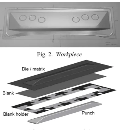
An asymmetrical workpiece was chosen from household appliances industry (Fig. 2). This workpiece is one of the component parts from a cooking device and was chosen because it looks simple. However, there were a lot of problems with it, especially with critical corner areas. This part has a valid special criterion because the part is visible on the end-product. No wrinkles, scratches or cracks are allowed.
The workpiece has a different depth of draw on both sides, on the higher side 36 mm and on the lower side 10mm. The dimensions of the initial blank are 660 x 220 x 0.7 mm. The computer models are simplified and are shown in Fig. 3. The main parts of the computer model contains die, blank, blank holder, segments’ inserts, and punch.
Volk M. – Nardin B. – Dolšak B.
2
Fig. 2. Workpiece
Fig. 3. Computer model
1.2 Basic parameters
The surfaces of the die, punch, blank holder and segments’ inserts were discretized, mainly by quadrangular surface elements and were assumed to be perfectly rigid. The blank was descretized by quadrangular surface elements and the plastic behaviour was descretized by Hollomon’s hardening law.
The dynamic explicit approach was chosen for calculating the forming-process.
Appropriate parameters such as friction, punch- velocity and drawing-radii were selected from the metal-forming handbooks and from previous research. These invariably geometrical parameters and process parameters are shown in Table 1. The maximal punch stroke or drawing height was 36mm; any workpieces made with a drawing height of less than 36mm were unacceptable.
Table 1. Geometrical andprocess parameters
Parameter Value
Punch velocity 5 m/s
Drawing radii 1,8 mm
Punch stroke 36 mm
Friction coefficient die/blank 0,1; punch/blank 0,12; holder/blank 0,1
1.3 Material properties of sheet metal
A commercially-available DC04 sheet metal with a thickness of 0.7 mm was used for the blank material and tensile tests were conducted to determine the material’s properties. The material model’s coefficients were identified based on stress-strain curves (Table 2).
The material was defined by Hollomon's hardening law [9, 10], and is given by i.e. (1):
n e
f
C
(1) Where σf is yield stress, C is strength coefficient,
φe is true strain, and n is hardening exponent.
Table 2. Material properties of sheet metal
Blank material DC04
Yield strength 188,9 N/mm2
Tensile strength 298,4 N/mm2
Elastic module 210000 N/mm2
Strength coefficient 384,98 N/mm2
Hardening exponent 0,21
Coefficient of anisotropy 1,78
2 RESULTS
The most significantly controlled parameter was the holding force. The first analyses were made with constant holding force on the blank holder. The holding force was optimized but good parts were still unachieved. Good workpieces are considered to be workpiece without wrinkles, cracks, scratches, and dimensional errors. The critical regions of the workpieces were in the corner areas where radial tensile stresses and tangential compressive stresses are present due to the material’s retention property. These compressive stresses often lead to flange wrinkles. Apart from wrinkles, another typical problem in sheet metal stamping is the generation of cracks. Workpieces made by holding forces of less than 400 kN had wrinkles
present and those with holding forces of more than 400 kN had cracks present. From the Fig. 4 it can be seen the critical areas where wrinkles and fissures occur.
In order to achieve good parts additional
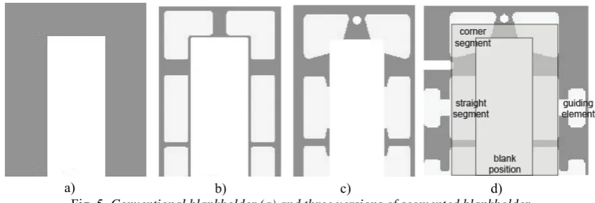
changes had to be made on the computer model. Therefore, segment holding systems were used with distributed holding forces. Optimizing techniques were used for testing the shapes of the segment inserts and the sizes of the local holding forces. Different shapes of segments’ inserts were numerically calculated and qualities of the workpieces estimated. The shapes of the segments and half of the holding system are shown in Fig. 5. All the holding systems consisted of 10 segments and one guiding blank holder. By using these systems, it is possible to distribute holding forces into 10 areas and each
Fig. 4. Critical areas of the workpiece; a) colour scheme, b) wrinkling trend and c) cracks
Fig. 5. Conventional blankholder (a) and three versions of segmented blankholder b)
a) c)
a) b) c) d)
Volk M. – Nardin B. – Dolšak B.
4
segment’s force could be separately controlled. The results showed that the best segment shape was option d (Fig. 5). The shape of the segments in this case was designed in such a way that the front parts of the straight segments are holding and the rear parts of the segments are guiding. The corner segments didn't need an extra guiding. The holding areas in all options were identical.
The results from these computer analyses are shown above. The main problems occurred on those areas shown in Fig. 6. Strong wrinkling tendencies occurred on the areas between the corners and the straight segments.
This flange-wrinkling may have had an effect on the end-product, therefore the proposed holding systems didn’t satisfy primary demands.
In order to solve this problem, the guiding blank holder was also supported by the holding force. The range of this holding force was from 10 kN to 100 kN. The results proved to be much better and the workpiece already satisfied the presumed demands of good parts. It was very interesting that the results with guiding blank holder forces of both 10 kN and 100 kN were similar, therefore the guiding blank holder force had had a big influence but the value of the force hadn't.
Finally, the segmented blankholder forces were optimized. The BH area was divided into ten segments; however this workpiece was symmetrical in one plane and, therefore only 6 segments were actually optimized. The defects were recognized and localized by a human and the desired trajectory of the holding force was adjusted only for those segments situated in that part where tearing or wrinkling occurred. Determination of how much to increase or decrease the values of holding forces depended of the sizes of the defects. As mentioned earlier, optimization was done using Fuzzy logic rules, which consisted of IF-THEN sentences which were chosen based on previous results of FEM analysis.
Table 3. IF-THEN sentences
IF Cracking THEN Decrease BHF
IF Wrinkling THEN Increase BHF
Using these rules all 6 segment's holding forces were optimized.
Numerous numerical simulations have to
be done to obtain the correct trajectories for holding forces. Good workpieces with no Fig. 6. Flange wrinkling; a) whole model, b) colour scheme, c) detailed view
a)
wrinkling and no cracks present on the model were made with a holding force from 306 kN to 734 kN (Fig. 7).
Fig. 7. Good workpieces made by segmented holding system a) with segmented holding forces
306kN b) with segmented holding forces 734kN
*
End-workpieces with a drawing-height of 36mm made by a holding force of less than 306 kN had wrinkles present and workpieces made by a holding force of more than 734 kN had cracks present. The ranges for the holding forces on each segment are shown in Fig. 8.
Fig. 8. Ranges for holding forces for each segment
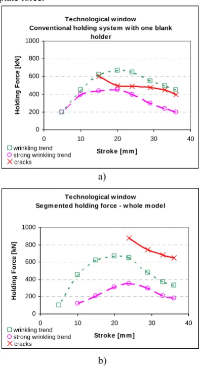
A new technological window was constructed and is shown in Fig. 9b. The technological window in the Fig. 9a was made with constant holding force and a conventional holding system with only one holding plate (option a in Fig. 5) and in Fig. 9b was made with a new holding system with segments’ inserts and with optimized holding forces (option d in Fig. 5). In the technological window with segmented holding force, the holding force is the sum of all
10 segmented forces and also the blankholder plate force.
Technological w indow
Conventional holding system w ith one blank holder
0 200 400 600 800 1000
0 10 20 30 40
Stroke [m m ]
H
o
ld
in
g Fo
rc
e
[k
N
]
Technological w indow Segm ented holding force - w hole m odel
0 200 400 600 800 1000
0 10 20 30 40
Stroke [m m ]
Ho
ld
in
g
F
o
rc
e
[
k
N
]
Fig. 9. Technological windows a)
wrinkling trend strong wrinkling trend
cracks
a) b)
wrinkling trend strong wrinkling trend
cracks
b)
The differences in the technological window regarding the corner areas and the straight areas, are shown in Fig.10. From these diagrams it is well seen that the corners area are more critical than straight areas.
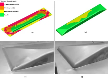
From all diagrams (Fig. 9 and 10) it is clear that the wrinkles in the corner areas had already occurred in the earlier steps of the deep-drawing process but later on some of the wrinkles disappear which was also confirmed by experiment (Fig. 11).
Volk M. – Nardin B. – Dolšak B.
6
Technological w indow Segm ented holding force - corner area
0 20 40 60 80 100
0 10 20 30 40 Stroke [m m ]
Co
rn
e
r F
o
rc
e
[
k
N]
Technological w indow Segm ented holding force - straight area
0 20 40 60 80 100
0 10 20 30 40 Stroke [m m ]
S
tr
a
ight For
c
e
[k
N
]
Fig. 10. Technological window for; a) corner areas and b) straight areas
wrinkling trend
strong wrinkling trend wrinkling trend
cracks cracks
a) b)
Fig. 11. Wrinkling trend a) step 4 (FEM), b) step 10 (FEM), c) early step (experiment) and d) final draw (experiment)
a) b)
*
3 CONCLUSION
Different holding systems were evaluated and the advantages and disadvantages are presented. The presented results for deep drawing show that the quality of a workpiece can be improved with a better holding system. It is evident that even small changes in BHF can lead to failure during the process. These failures can be avoided if a variable BHF is applied, but the correct trajectories need to be chosen. This work shows that the results using guiding blank holder forces of 10kN and 100kN were similar. Therefore guiding blank holder force had a big influence but value of the force hadn't.
Taking into account the geometric restrictions of the die, the segments’ inserts’ shapes were also highlighted. Finally FEM analyses segmented holding forces were optimized. Numerous numerical simulations were done and technological windows for each area given.
However, the analyses did not consider spring-back. Spring-back in sheet metal forming can be described as the change in sheet metal shape compared with the shapes of tools after the forming process. Currently FEM calculations for spring-back is not relevant, therefore further research should be carried out to find out the effects of different holding systems on the spring-back effect during sheet metal stamping processes.
Acknowledgement
Practical part of the research was made in Gorenje Orodjarna d.o.o.
Operation part financed by the European Union, European Social Fund
This work is part of the 7th framework program, research and development project, Self-Learning sheet metal forming system (LearnFORM), Grant agreement N° NMP2-SL-2009-228346
4 REFERENCES
[1] Gantar, G., Kuzman, K., Filipič B. Increasing the stability of the deep drawing process by
simulation-based optimization, Journal of
Materials Processing Technology, Vol. 164-165, 2005, p. 1343-1350
[2] Pepelnjak, T., Kampuš, Z. Analysing the Quality of Sheet-Metal holding during deep
Drawing, Strojniski vestnik – Journal of
Mechanical Engineering, 47 (2001), p. 94-105 [3] Chen, D., Chen, W., Lin, J., Jheng, M., Chen J. Finite element analysis of superplastic blow-forming of Ti-6Al-4V sheet into closed ellip-cylindrical die, IJSIMM, Vol. 9, No. 1 (2010) p. 17-27
[4] Jerman, B., Hodnik, R., Kramar, J. An analysis of the Spreading of a Holding Pressure by Means of Pliable Blank Holder with the Controllable Holding Force during a Deep-Drawing Process, Strojniski vestnik – Journal of Mechanical Engineering, 47 (2001), p. 83-93 [5] Zhao, J., Wang, F. Parameter identification by neural network for intelligent deep drawing of
axisymmetric workpieces, Journal of Materials
Processing Technology, Vol. 166 (2005), p. 387-391
[6] Koyama, H., Wagoner, R., Manobe, K. Blank holding force control in panel stamping process using a database and FEM-assisted intelligent
press control system, Journal of Materials
Processing Technology, Vol. 152 (2004), p. 190-196
[7] Yagami, K., Manobe, Y., Yamauchi, Y. Effect of alternating blank holder motion of drawing and wrinkle elimination on deep-drawability, Journal of Materials Processing Technology, Vol. 187-188 (2007), p. 187-191
[8] Manobe, K., Koyama, H., Yoshihara, S., Yugami, T. Development of a combination punch speed and blank-holder fuzzy control system for
the deep-drawing process, Journal of Materials
Processing Technology, Vol. 125-126 (2002), p. 440-445
[9] Gologranc, F. (1991). Preoblikovanje (in Slovenian language), Faculty of mechanical engineering, Ljubljana
[10] Kuzman, K.; Kampuš Z. (1995). Priporočila
za načrtovanje tehnologij preoblikovanja (in
![Fig. 1. Technological window [1]](https://thumb-us.123doks.com/thumbv2/123dok_us/8952062.1861430/1.595.107.262.514.662/fig-technological-window.webp)