IJEEE, Vol. 2, Issue (April, 2015) e-ISSN: 1694-2310 | p-ISSN: 1694-2426
OBSTACLE AVOIDANCE AND
ANDEROID MOBILE PHONE
CONTROLLED BLUETOOTH ROBOT
USING ARDUINO
1
Ashima,
2Rajan Kumar,
3T. Nikhil,
4Paramdeep Singh
1,2,3B.Tech ECE, Student, Lovely Professional University4
Assistant Professor, Lovely Professional University 1
[email protected], [email protected], [email protected], [email protected]
Abstract- This project is focused to make mobile robots as the target application and problems that will be covered include: how to design - wheeled ground robots avoid collisions while reaching target locations, by using Arduino Uno R3. The robot is made of L293D interface circuit Arduino board and a motor driving system. The robot controlling devices are connected to the Arduino board. The Arduino board transmits signals to the interfacing board L293D which controls the motor driving system. Robots can also be utilized as an obstacle avoiding robot. IR sensor is used for obstacle avoidance of robot in which we insure that Robot doesn’t have to stop in front of an obstacle which allows to navigate smoothly in unknown environments, avoiding obstacles.
Index Terms- Arduino Uno R3, DC Motor, HC-05, IR Sensor, L293d.
I. INTRODUCTION
Today the android has become very familiar in the world. Google Android OS is running Millions of devices and millions are being developed daily for common use of people. There are millions of developers of the Google and it has made the Android development platform open to everyone around the world. Some developers just focus on building the apps or games for the android devices, but these apps are having numerous possibilities as well in this field. [1] Now a days Smartphones are becoming more powerful with reinforced processors, larger storage capabilities, richer entertainment functions and more communication methods. It is especially useful in a home environment. With the use of Bluetooth technology and other similar techniques, the concept of Smart Living has offered better opportunity in convenience, comfort and security which includes centralized control of air conditioning, lighting, heating and cooling at home, and service robots[2][3]. Now with the excessive use of smartphone users, smartphones have gradually turned into an all-purpose portable device and provided people for their daily use [4]. An open-source platform Android has been widely used in smartphones[5] [6].
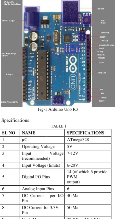
Arduino Uno R3- Arduino is an open-source electronics prototyping platform which is based on flexible, more easy-to-use hardware and programing software. If anyone interested in creating interactive objects or environments this is intended for
artists, most of the designers, and hobbyists. Arduino can affect its surroundings by controlling lights, motors, and other actuators and can sense the environment by receiving input from a variety of sensors.
Fig-1 Arduino Uno R3
Specifications
TABLE 1
SL NO NAME SPECIFICATIONS
1. µC ATmega328
2. Operating Voltage 5V
3. Input Voltage 7-12V
(recommended)
4. Input Voltage (limits) 6-20V
5. Digital I/O Pins
14 (of which 6 provide PWM
output)
6. Analog Input Pins 6
7. DC Current per I/O 40 Ma Pin
8. DC Current for 3.3V 50 Ma Pin
used by the Boot loader
10. SRAM 2 KB
11. EEPROM 1 KB
12. Clock Speed 16 MHz
II. COMPONENT USED
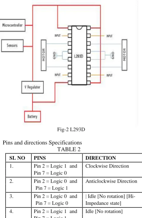
L293D- It works on the concept of H-bridge. H-bridge is a circuit which allows the voltage to be flown in either direction. As you know voltage need to change its direction for being able to rotate the motor in clockwise or anticlockwise direction, hence H-bridge IC are ideal for driving a DC motor. In a single l293d chip there two h-Bridge circuit inside the IC which can rotate two dc motor independently.
Fig-2 L293D
Pins and directions Specifications TABLE 2
SL NO PINS DIRECTION
1. Pin 2 = Logic 1 and Clockwise Direction Pin 7 = Logic 0
2. Pin 2 = Logic 0 and Anticlockwise Direction Pin 7 = Logic 1
3. Pin 2 = Logic 0 and | Idle [No rotation] [Hi-Pin 7 = Logic 0 Impedance state]
4. Pin 2 = Logic 1 and Idle [No rotation] Pin 7 = Logic 1
HC Serial Bluetooth -HC Serial Bluetooth product Consists of Bluetooth serial interface module and Bluetooth adapter. Bluetooth serial module is used for converting serial port to Bluetooth. This module has two modes: master and slaver device.
HC-05 Specifically includes: Master device: HC-05-M, M=Master Slaver device: HC-05-S, S=Slaver
DC Motor-Every mechanical movement that which we see around us is accomplished by an electric motor. Since Motors take electrical energy and produce mechanical energy. [27] Here electric motors are broadly classified into two different categories: Direct Current and Alternating Current. These
categories are numerous types, each offers unique abilities that suit them well for specific applications. Robot chasse and Components- The chassis or the vehicle base, which can support a circuit board, 12V battery and wheels, is casted out of steel as shown.
Fig-3 Chasse Parts
IR Sensor
Fig-4 Sensor Description
PIN CONNECTION DESCRIPTION
NO
1. Output Digital Output (High or Low)
2. VCC Connected to circuit supply
3. GND Connected to circuit Ground
III.WIRE CONNECTIONS AND BLUETOOTH PLACEMENT
1. The L293D is connected to power supply which supplies power to the Arduino board.
2. Left Motor is connected to 11 and 14 Pin of the L293D board.
3. Right Motor is connected to 6 and 3 Pin of the L293D board.
4. Pin 4 of the Arduino is connected to input PIN 15in the L293D board.
5. Pin 5 of the Arduino is connected to input PIN 10 in the L293D board.
6. Pin 6 of the Arduino is connected to input PIN 7 in the L293D board.
7. Pin 7 of the Arduino is connected to input PIN 2 in the L293D board
8. TX of HC-05 is connected to RX of Arduino.
9. Pin 9, 1, 8, 16 of L293d and VCC of HC-05 is connected to +5V of Arduino.
10. Pin 4, 5, 12, 13 of L293d and GND of HC-05 is connected to GND of Arduino.
Application Instructions
1. First make sure your HC-05 Bluetooth module is paired with your mobile. The default password for pairing is “1234”. Check the manual of Bluetooth module.
2. Click on “SELECT DEVICE” icon to select paired Bluetooth module.
3. When press “up arrow” it sends the data “A” to Bluetooth module connected with the circuit.
When microcontroller detects “A” the robot/robot car moves FORWORD.
4. When press “DOWN ARROW” it sends the data “B” to Bluetooth module connected with the circuit. When microcontroller detects “B” the robot/robot car moves REVERSE.
5. When press “LEFT ARROW” it sends the data “C” to Bluetooth module connected with the circuit. When microcontroller defects “C” the robot/robot car turns LEFT.
6. When press “RIGHT ARROW” it sends the data “D” to Bluetooth module connected with the circuit. When microcontroller defects “D” the robot/robot car turns RIGHT.
7. When press “STOP” button which is in the center of remote it sends the data “E” to the Bluetooth module connected with the circuit. When microcontroller defects “E” the robot/robot car gets stopped.
8. Click on “DISCONNECT” icon to disconnect paired Bluetooth module.
Fig-5 Blue Control App
IV. Methodology USED
Fig-6 Flow chart of IR Sensor
The "stopped" state will be for when the robot is not moving at all. The "moving" state will be for when the robot is moving forward. Finally, the "turning" state will be used while the robot is turning. The robot will begin in stateMoving state and will run for a limited amount of time, after which will change to the stateStopped state. The first two decisions in the flowchart address that part of the logic.
If the robot is in stateMoving it will check for obstacles, and if one is found it will turn, which changes the state to stateTurning. If no obstacles are found then it will not change its state. If the robot is in stateTurning it will check if it is done turning, at which point it will change back to stateMoving. If the turn isn't complete then it will remain in the same state.
VII. SOFTWARE
both the looks and the functionality that appeal to Arduino developers, paving the way to a successful output via the debugging modules.
Arduino Software Interface-The Arduino interface is pretty“bare
-bones”. When you load the software, the first screen you will see
is a white window with several different shades of blue and blue-green as border. Arduino projects are called
“sketches” and you start a new sketch, several additional files are also created. Arduino programs are written in C or C++. The Arduino IDE comes with a software library called "Wiring" from the original Wiring project, which makes many common input/output operations much easier. The white area is where the program is written. The programming language that the Arduino platform uses is called C++ a language that is regarded as very powerful but difficult to learn. C++ programs are written as regular text. Arduino calls these programs
Sketches. Then a utility called compiler reads the sketch and
converts it to machine instructions that the Arduino understands. The black area at the bottom of the Arduino software window is where status information appears.
Fig-7 Arduino IDE
Following are the steps involved to start Software[7] 1. Open Arduino IDE as shown below
2. Select the COM Port from tools
3. Select the required Arduino board from Tools as shown below
4. Write the sketch in Arduino IDE
5. compile and upload the Sketch to Arduino board
The Arduino software toolbar, with the following buttons.
Verify: Runs the C++ compiler on your program. If there are any errors you will see them in black status area.
Upload: Compiles your C++ program like the Verify button does, and if compilation is successful it uploads the resulting program to the Arduino board, which must be connected to the computer through the USB port.
New: Clears the program currently loaded.
Open: Shows a dropdown with a long list of example programs to load or the option to load a sketch from disk.
Save: Saves the current program to a file on disk.
Serial Monitor: Opens the serial monitor console. This is used mostly for debugging
RESULTS -A new real-time obstacle avoidance approach for mobile robots has been developed and implemented. The experiment demonstrated that the system design was effective
– at least as far as its current application goes. Wider tests and enhancements need to be carried out to investigate its feasibility with many moving agents and obstacles, and conflicting agent goals. The success of the initial system, however, is encouraging and indicative that the method is an effective approach to tackling the problem.
Fig-8 Block Diagram
Almost all navigation robot demands the some sort of obstacle detection, hence obstacle avoidance strategy is of utter importance. Obstacle avoidance robot has a vast field of application. They can be used as services robots, for the purpose of household work and so many other indoor applications. [8] In those challenging environments, the robots need to gather information about their surroundings to avoid obstacles. Nowadays, even in ordinary environments, people also require that robots can detect and avoid obstacles.
Fig-9 Final Output
IX. CONCLUSION
Almost all navigation robot demands the some sort of obstacle detection, hence obstacle avoidance strategy is of utter importance. Obstacle avoidance robot has a vast field of application. They can be used as services robots, for the purpose of household work and so many other indoor applications.[49]In those challenging environments, the robots need to gather information about their surroundings to avoid obstacles. Nowadays, even in ordinary environments, people also require that robots can detect and avoid obstacles. For example, an industrial robot in a factory is expected to avoid workers so that it won’t hurt them. In conclusion, obstacle avoidance is widely researched and applied in the world, and it is probable that most robots in the future should have obstacle avoidance function. [50]Various techniques have emerged to develop the science of robotics and robots. One method is evolutionary robotics, in which a number of differing robots are submitted to tests like obstacle avoidance system. Those which perform best are used as a model to create a subsequent "generation" of robots. There are concerns about the increasing use of robots and their role in society. Additional features can be easily incorporated into this module if required, long range sensors can be used. The speed of the robot can be controlled. A wire-less RF remote can be used to control the robot. Use of differential steering with gradual change in wheel speeds. Use of Hysteresis in sensor circuit using LM339. Increment in number of sensors to enhance the obstacle detection capability. Incorporation of a camera whose data can be sent through wireless. Incorporation of robotic hand to remove the obstacle in case there is no way for the movement of the robot.
ACKNOWLEDGMENT
First of all we want to pay thanks to the Almighty LORD for his blessings. At the very outset, we are thankful and express out sincerest and deepest gratitude to Lovely Professional University for providing us all the needed infrastructure and wonderful research environment. We are thankful and express our sincerest and deepest gratitude to my supervisor, Mr. Paramdeep Singh, Asst. Professor, Department of Electronics and Communication, Lovely Professional University, Phagwara, Punjab for his vast assistance during the entire project work in preparing and editing my work, considerate discussions, constant encouragement, and direction. Then we would like to express our heartfelt gratitude to IJEEE Publication for allowing us to publish our Research Work. Besides that we also want to thanks our fellow colleagues for being there whenever we needed them. We must express our sincere thanks to all the persons who helped directly or indirectly with his/her advice or suggestions. And ultimately, we would like to thank our parents for their constant encouragement when it was most required.
REFERENCES
[1] Kishan Raj (2012) Controlling a Robot using Android Interface and voice, Turku University of applied Sciences, Thesis. [2] Dimitrakopoulos, G., Tsagkaris, K., Stavroulaki, V., Katidiotis,
A., Koutsouris, N., Demestichas, P., Merat, V. and Walter, S. (2008) "A Management Framework for Ambient Systems Operating in Wireless B3G Environments", Springer Mobile Networks and Applications, Vol. 13, No. 6, pp. 555-568. [3] Savic, S. and Shi, H. (2011) an Intelligent Object Framework for
Smart Living, Procedia Computer Science 5 (2011) 386–393. [4] Adams, C. and Millard, P. (2003) "Personal Trust Space and
Devices: "Geography will not be History" in the m-commerce future". Hawaii International Conference on Business (HICB2003), 18-21 June 2003, Sheraton Waikiki Hotel, Honolulu, Hawaii, USA.
[5] Chung, C.-C., Wang, S.-C., Huang, C. Y., and Lin, C.-M. (2011) "Bluetooth-based Android Interactive Applications for Smart Living", 2011 Second International Conference on Innovations In Bio-inspired Computing and Applications (IBICA-2011), Shenzhen, China, 16-18December 2011, pp.309-312.
[6] Ming Yan and Hao Shi (February 2013), Smart living using Bluetooth based Android Smartphone, International Journal of Wireless & Mobile Networks (IJWMN) Vol. 5, No. 1.
[7] Arduino Cookbook, 2nd Edition by Michael Margolis.