International Journal of Engineering
J o u r n a l H o m e p a g e : w w w . i j e . i rA Size-dependent Bernoulli-Euler Beam Formulation based on a New Model of
Couple Stress Theory
R. Akbari Alashti*, A. H. Abolghasemi
Department of Mechanical Engineering, Babol University of Technology, Babol, Iran,
P A P E R I N F O
Paper history:
Received 14 September 2013
Received in revised form 01 November 2013 Accepted 07 November 2013
Keywords:
Bernoulli-Euler Beam Couple Stress Theory Microstructural Effect Static Bending Free Vibration
A B S T R A C T
In this paper, a size-dependent formulation for the Bernoulli-Euler beam is developed based on a new model of couple stress theory presented by Hadjesfandiari and Dargush. The constitutive equation obtained in this new model, consists of only one length scale parameter that is capable of capturing the micro-structural size effect in predicting the mechanical behavior of the structure. Having one length scale parameter is claimed to be an advantage of the model in comparison with the classical couple stress theory. The governing equations and boundary conditions of the Bernoulli-Euler beam are developed using the variational formulation and the Hamilton principle. The static bending and free vibration problems of a Bernoulli-Euler beam with various boundary conditions are solved. Numerical results demonstrate that the value of deflection predicted by the new model is lower than that of the classical theory. It is also found that natural frequencies obtained by the present couple stress model are higher than those predicted by the classical theory. The differences between results obtained by the present model and the classical theory become significant as the thickness of the beam gets close to the length scale parameter of the beam material
doi: 10.5829/idosi.ije.2014.27.06c.14
1. INTRODUCTION1
The classical theory of elasticity is not capable of capturing the size effect of microstructure and is appropriate to study material behavior in macro-scale only. When the scale of the material under study decreases, the accuracy of the classical theory decreases and as a result its prediction of the material behavior in micro and nano-scale doesn’t agree with experimental results. The reason for such deviation is found to be the significant effect of microstructure [1-5]. Hence, the non-classical theories such as the strain gradient or couple stress theories are employed to study the behavior of materials in these scales. Non-classical theories contain length scale parameters which indicate the effect of microstructure in the behavior of the material. The couple stress theory is found to be the simplest kind of such theories.
The classical couple stress theory was presented by Mindlin and Tiersten [6], Toupin [7], Koiter [8] and some other researchers. This theory considers the
*Corresponding Author Email: [email protected] (R. Akbari Alashti)
gradient of rotation in addition to the gradient of displacement, but the rotation is assumed to be dependent to the displacement as seen in the classical theory. Constitutive equations developed for an isotropic material on the basis of the classical couple stress theory contain four elastic constants, i.e. two Lame’s constants and two length scale parameters. Anthoine [9] solved the pure bending problem of a circular cylinder employing the couple stress theory. Zhou and Li [10] analyzed the static bending and free vibration problems of a circular cylinder on the basis of the couple stress theory. Asghari, et al. [11] developed a size-dependent formulation for Timoshenko beam on the basis of couple stress theory. Yang, et al. [12] propounded a model of couple stress, i.e. the modified couple stress theory that considers an additional equilibrium equation for the moment of couple, in addition to two equilibrium equations of the classical continuum. Application of this equilibrium equation, leads to a symmetric couple stress tensor and a constitutive relation that has only one length scale parameter. Park and Gao [13] studied the static bending problem of the Bernoulli-Euler beam. The governing equations and boundary conditions were developed
using variational method on the basis of the modified couple stress theory. Kong, et al. [14] solved the dynamic problem of Bernoulli-Euler beam and obtained the natural frequencies of the beam based on the modified couple stress theory. Asghari, et al. [15] carried out the static bending and free vibration analysis of a functionally graded Bernoulli-Euler micro beam based on the modified couple stress theory.
The microstructure-dependent formulation for the Timoshenko beam, functionally graded Timoshenko beam and nonlinear Timoshenko beam were developed by Ma, et al. [16], Asghari, et al. [17, 18], respectively. Simsek, et al. [19] investigated the static bending of a functionally graded Timoshenko beam on the basis of the modified couple stress theory. Chen, et al. [20] presented a new model to study the behavior of a laminated anisotropic composite Reddy beam based on the modified couple stress theory.
Ke, et al. [21] solved the nonlinear free vibration problem of a micro-beam made of functionally graded material according to the modified couple stress theory. Free vibration analysis of a three dimensional cylindrical micro-beam and nonlinear dynamic analysis of a micro-beam based on the modified couple stress theory were carried out by Wang, et al. [22] and Ghayesh, et al. [23], respectively.
Hadjesfandiari and Dargush [24] presented a model of couple stress theory in which the couple stress tensor is found to be antisymmetric due to lack of the normal components of the couple stress tensor on the boundary of the element in a couple stress continuum. The constitutive equations developed by this model consist of only one length scale parameter.
Althoght there are a number of papers dealing with micro-beams using non-classical theories but to the knowledge of the authors, the couple stress model developed by Hadjesfandiari and Dargush [24] has not been employed to study the behavior of micro-beams. The purpose of this paper is to study the behavior of a Bernoulli-Euler beam using the new model of couple stress developed by Hadjesfandiari and Dargush [24]. At first, kinematic variables in a couple stress continuum are defined. Then, the governing equations and boundary conditions are obtained using the variational formulation and Hamilton principle.
The static bending and free vibration problems of a Bernoulli-Euler beam with different boundary conditions are solved analytically. It is found that the value of deflection of the beam obtained by the proposed model of couple stress is lower than that of the one obtained by the classical beam theory. On the other hand, values of natural frequencies of vibration of the beam becomes higher than those obtained by the classical theory. At the end, values of deflection and natural frequency a micro-beam obtained by the present couple stress model are compared with those predicted by the modified couple stress theory.
2. PRELIMINARIES
According to the model of couple stress developed by Hadjesfandiari [24], the strain energy of an isotropic linear elastic material experiencing an infinitesimal displacement is defined as:
(
)
1
2 i j i j j i ij
U s e m m d V
W
=
ò
+ (1)where, sij,eij,mji and mij are components of stress, strain, couple stress and antisymmetric curvature tensors, respectively. These tensors can be defined as [24]:
( ) 2
ij tr ij ij ij
s =l e d + me (2)
(
, ,)
12
ij ui j uj i
e = + (3)
2
8
ji ji
m = - m ml (4)
(
, ,)
12
ij i j j i
m = w -w (5)
where,
(1 )(1 2 ) , 2 1( )
Eu E
l m
u u u
= =
+ - + (6)
are Lame’s constants, E is the Young’s modulus, u is the Poisson’s ratio, l is the length scale parameter; ui
and wi are components of the displacement and the rotation vectors, respectively. Components of the rotation vector can be defined in terms of components of the displacement vector in the following form;
,
1 2
i e uijk k j
w = (7)
where,
e
ijk is the permutation tensor.It can be easily concluded from Equations (2) and (4) that the stress tensor and the couple stress tensor are symmetric and antisymmetric, respectively.
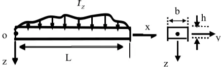
As shown in Figure 1, the Cartesian coordinate system is employed for the beam under study that consists of x, y and z-axis as centroidal, neutral and symmetry axis, respectively. According to the Bernoulli-Euler beam theory, the displacement field can be written as [13, 14]:
( )
( )
1 2 3
,
, 0, ,
w x t
u z u u w x t
x 
= - = =
¶ (8)
where, u1, u2 and u3 are components of the displacement vector of a point with coordinates
(
x y z, ,)
vector in the z-direction of the point on the centroidal axis with coordinates
(
x,0,0)
.Using Equations (3) and (8), components of the strain tensor can be expressed as:
2
2, 0
xx yy zz xy yz xz
w z
x
e = - ¶ e =e =e =e =e =
¶ (9)
And using Equations (7) and (8), the components of rotation vector can be obtained as:
0
y x z
w x
w = -¶ w =w =
¶ (10)
From Equations (5) and (10), it follows that:
2 2
1
, 0
2
xy yx xz zx yz zy
w x
m = -m = ¶ m =m =m =m =
¶ (11)
Since, the beam is assumed to be slender with a large aspect ratio, the effect of Poisson’s ratio is very small and can be neglected. Inserting Equation (9) into Equation (2) yields:
2
2, 0
xx yy zz yz zx xy
w Ez
x
s = - ¶ s =s =s =s =s =
¶ (12)
And substitution of Equation (11) into Equation (4), results: 2 2 2 0 xy yx
xx yy zz yz zx
w
m m l
x
m m m m m
m 
= - =
-
= = = = =
(13)
Once, the kinematic parameters are defined, we can proceed further to obtain the governing equations.
3. GOVERNING EQUATIONS
In this section, the governing equations and boundary conditions are obtained using the variational formulation and the Hamilton principle. The first variation of the strain energy in the time interval
[
0 ,T]
is obtained from Equation (1):0 0 0
T T T
ij ij ji ij
Udt dV dt m dV dt
d s de dm
W W
= +
ò
òò
òò
(14)where, W is the region occupied by the beam.
Using Equations (9) and (11), the Equation (14) can be rewritten as: 2 2 2 2 0 0 T T xx xy w w
z dV dt m dVdt
x x
d d
s
W W
æ- ¶ ö + æ- ¶ ö
ç ¶ ÷ ç ¶ ÷
è ø è ø
ò ò
ò ò
(15)The stress and couple stress resultants through the cross-section of the beam are found to be:
Figure 1. Configuration and coordinate system of the loaded beam
/ 2 /2
0 / 2 0 /2
;
b h b h
xx xx xy xy
h h
M s zdzdy Y m dzdy
-
-=
ò ò
=ò ò
(16)where, h and b are the thickness and the width of the beam, respectively. Substituting Equation (16) into Equation (15) results in the following relation:
2 2
2 2
0 0 0 0
T L T L
xx xy
w w
M dxdt Y dxdt
x x
d d
æ- ¶ ö + æ- ¶ ö
ç ¶ ÷ ç ¶ ÷
è ø è ø
òò
òò
(17)where, L is the length of the beam.
Using the divergence theorem in above equation, the following relation is obtained:
(
)
2 2
2 2
0 0 0
0 0 0 0
T T L
xy xx
x L x L
T T xy xx xx xy x x Y M Udt wdxdt x x Y M w
w dt M Y dt
x x x
d d d d = = = =
æ¶ ¶ ö
ç ÷
= - ç + ÷
¶ 
è ø
æ¶ ö 
+ ç ¶ + ¶ ÷ - + 
è ø
ò
òò
ò
ò
(18)
The variation of kinetic energy in the time interval [0,
T] can be expressed as:
2
2
0 0 0
T T L
w
Kdt A wdxdt
t
d = - æçr ¶ ö÷d
è ø
ò
òò
(19)where,
r
is the mass density of the beam material that is assumed to be independent of the time,t
and the position,x
and Ais the area of the cross-section of the beam that is defined as:A bh= (20)
The virtual work done by the external forces applied on the beam in the time interval
[
0,T]
can be expressed as [16]:0 0 0
0 0
{ }
{ }
T T L
z y y
T
x L y y x
W dt f w c d xd t
V w s dt
d d dw
d dw =
=
= +
+ +
ò
ò ò
ò
(21)
In above equation, fz and cy are the body force and body couple per unit length of the beam, respectively; V is the applied transverse force on the beam and
s
yis the applied couple stress about the y-axis. In the absence of the body couple and the surface force and surface couple, the virtual work becomes:
0 0 0
T T L
z
W dt f w dxdt
d
ò
=ò ò
d (22)The Hamilton principle is defined in the following form [16]:
(
)
0
0
T
K U W dt
d
ò
é -ë - ùû = (23)By substituting Equations (18), (19) and (22) in Equation (23), the governing equation of the Bernoulli-Euler beam can be obtained as:
2 2
2 2 0
xy xx
z
Y
M f
x x
¶ + + =
¶ ¶ (24)
And the boundary equations are defined as follow:
;
xy xx
xx xy
Y
M w
w or or M Y
x x x
¶ + ¶ +
¶ ¶ ¶ (25)
From Equations (12), (13) and (16), it follows that:
2 2
2
2 , 4 2
xx xy
w w
M EI Y Al
x m x
¶ 
= - =
-¶ ¶ (26)
Substituting Equation (26) into Equations (24) and (25) results in the governing equation and boundary conditions in terms of components of the displacement vector in the following form:
(
)
2 4
2
2 4 4 z 0
w w
A E I Al f
t x
r ¶ + + m ¶ - =
¶ ¶ (27)
(
)
32 3
4 w
w or EI Al
x
m 
- +
¶ (28a)
(
)
22 2
4
w w
or E I A l
x m x
¶ - + 
¶ ¶ (28b)
It can be seen from Equation (27) that the governing equation of the Bernoulli-Euler beam is composed of two parts: one is related to rAand EI and the other to
2
4mAl . The first part is the same as the one in the classical theory and the second part is added due to the couple stress theory. The additional term increases the stiffness of the beam that in turn decreases the deflection of the beam and increases its natural frequencies. It is seen from Equation (27) that Hadjesfandiari’s couple stress model contains one length scale parameter beside two conventional classical constants. This length scale parameter enables the present couple stress model to describe the size effect. When the length scale of the material vanishes (l =0), the governing equation and boundary conditions
obtained in the present model reduces to the classical theory.
By comparing the governing equation and boundary conditions of the Bernoulli-Euler beam of the present model with those of the modified couple stress theory in [13, 14], it is found that these equations differ by a scalar factor. This scalar factor comes into effect due to the difference of definitions of the length scale parameter in the present model and the modified couple stress theory. The length scale parameter in Hadjesfandiari’s couple stress model is found to be half of the length scale parameter of the modified couple stress theory.
The present model of couple stress theory has two advantages in comparison with other non-classical theories. First is the existance of only one length scale parameter in the constutive relations, due to difficulties observed in determining the length scale parameter of a material [25]. The second one is the antisymmetry of the curvature tensor and the couple stress tensor. The strain energy in this theory includes only the antisymmetric part of the curvature and couple stress tensorsresulting in asimpler form of the strain energy in comparison with other non-classical theories.
4. CASE STUDY
In this section, the static bending and free vibration problems of the beam are solved employing the formulation derived in the previous section on the basis of Hadjesfandiari’s couple stress model. The problems are solved analytically for three boundary conditions and results are compared with those of the classical theory of elasticity.
4. 1. Static Bending Problem For the static bending problem, all derivatives with respect to time vanish and the governing equation is reduced to the following form
(
)
42 4
4 z
w
E I A l f
x
m 
+ =
¶ (29)
It is supposed that the beam is loaded under a constant distributed load, fz( )x =q0. Assuming such conditions,
analytical solution of Equation (29) can be obtained by successive integration as follow:
(
)
4 3 2
0
1 2 3 4
2 24 6 2
4
q x x x
w C C C x C
EI mAl
= + + + +
+ (30)
where, C1, C2, C3 and C4are coefficients that can be determined from boundary conditions.
beam with clamped-clamped boundary conditions are expressed in the following form:
0
(0) ( ) 0, x x L 0
w =w L = dw dx = =dw dx = = (31)
By applying above boundary conditions to Equation (30), unknown coefficients are obtained and the deflection becomes:
(
0 2)(
4 2 3 2 2)
24 4
q
w x Lx L x
EI mAl
= - +
+ (32)
By setting
l
=0, the above equation reduces to the result of the classical couple stress theory(
4 3 2 2)
0 2
24 q
w x Lx L x
EI
= - + (33)
By neglecting the effect of the Poisson’s ratio, the normalized static deflection of the clamped micro-beam is introduced as follow:
(
2)
(
)
21
4 1 24 /
w EI
w = EI+ mAl = + l h (34)
4. 1. 2. Simply Supported (S-S) Beam The boundary condition of a simply supported beam are defined as:
2 2 2 2
0
(0) ( ) 0, 0
x x L
w w L d w dx d w dx
= =
= = = = (35)
Using Equations (35) and (30), the unknown coefficients are determined and the transverse deflection is obtained as:
(
0 2)(
4 2 3 3)
24 4
q
w x Lx L x
EI mAl
= - +
+ (36)
When the length scale parameter tends to zero, l=0, Equation (36) reduces to the value of deflection obtained by the classical theory.
The normalized static deflection of the beam with simply supported ends can be presented as follow which is similar to the value corresponding to the clamped beam
(
2)
(
)
21
4 1 24 /
w EI
w = EI + mAl = + l h (37)
4. 1. 3. Cantilever (C-F) Beam According to Equation (28a) and (28b), the boundary conditions of a cantilever beam can be expressed as:
2 2 3 3
0
(0) 0, x 0, 0
x L x L
w dw dx = d w dx d w dx
= =
= = = = (38)
By applying the above boundary conditions, unknown coefficients of the Equation (30) are obtained and as a result, the transverse deflection of the beam is calculated as:
(
0 2)(
4 4 3 6 2 2)
24 4
q
w x x L L x
EI mAl
= - +
+ (39)
The value of the deflection of the beam according to the classical theory can be obtained by letting the length scale parameter equal to zero, l=0. The normalized static deflection of the cantilever beam is introduced as follow which is similar to the values obtained for two other boundary conditions.
(
2)
(
)
21
4 1 24 /
w EI
w = EI + mAl = + l h (40)
4. 2. Free Vibration Problem The size-dependent
vibration analysis of the micro-beam is carried out in this section. For this purpose, three boundary conditions namely clamped (C-C), simply supported (S-S) and cantilever (C-F) beams are considered. The natural frequencies of the micro-beam is solved analytically using the governing equation and boundary conditions derived in the previous section. For free vibration problems, the applied force is assumed to be zero
(fz =0).
4. 2. 1. Clamped (C-C) Beam The boundary
conditions for clamped beam are:
( )
( )
0
0, , 0
( , ) x ( , ) x L 0
w t w L t
w x t x = w x t x =
= =
¶ ¶ = ¶ ¶ = (41)
Employing the method of separation of variables and substituting the Equation (41) into Equation (27) yields to [26]:
(
)
cos(bL) cosh bL =1 (42)
Solution of Equation (42) leads to the following results [26]:
( )
4.7300, 7.8532, 10.9956, 14.1372,... 1,2,3,4,...n
L n
b =
= (43)
where, the natural frequency can be expressed as follow [26]:
( )2
2 (EI 4 Al2) ( A) L (EI 4 Al2) ( AL4)
w b= + m r = b + m r (44)
By letting the length scale parameter equal to zero, l=0
, the natural frequency of the beam according to the classical theory is obtained:
( )
L 2 EI ( AL4)w= b r (45)
The normalized natural frequency are determined as:
(
)
22
1 (4 Al ) /EI 1 24 l h/
w m
4. 2. 2. Simply Supported (S-S) Beam The boundary conditions in simply supported beam can be expressed as:
( )
(
)
2 2 2 2
0
0, , 0
( , ) ( , ) 0
x x L
w t w L t
w x t x w x t x
= =
= =
¶ ¶ = ¶ ¶ = (47)
with the aid of the separation method of variables and by substituting Equation (47) into Equation (27), yields to the following relation [26]:
( )
sin bL =0 (48)
(
1,2,3,...)
L n n
b = p = (49)
where, the natural frequency of the beam according to the present couple stress theory can be expressed as [26]:
( )n 2 (EI 4 Al2) ( AL4)
w= p + m r (50)
As the length scale parameter of the beam approaches to zero, the Equation (50) reduces to natural frequency of vibration of the beam according to the classical theory. The normalized natural frequency of the beam is defined as follow which is similar to the value of the clamped beam.
( )2 2
1 (4 Al ) (EI) 1 24 l h/
w m
w= + = + (51)
4. 2. 3. Cantilever (C-F) Beam The boundary condition of a cantilever beam can be expressed as follow:
( ) 0
2 2 3 3
0, ( , ) 0
( , ) ( , ) 0
x
x L x L
w t w x t x
w x t x w x t x
=
= =
= ¶ ¶ =
¶ ¶ = ¶ ¶ = (52)
With the aid of separation method of variables and substituting Equation (52) into Equation (27), leads to the following relation [26]:
(
)
cos(bL) cosh bL = -1 (53)
where, [25]
( )
1.8751, 4.6941, 7.8547, 10.9956,... 1,2,3,4,...n
L n
b =
= (54)
The natural frequency of the cantilever beam according to the new couple stress theory can be obtained as [26]:
(
)
2 2
2 2 4
( 4 ) ( )
( 4 ) ( )
EI Al A
L EI Al AL
w b m r
b m r
= +
= + (55)
The natural frequency of the beam according to the classical theory are obtained by letting the length scale parameter equal to zero, l =0. The normalized natural
frequency of the beam can be expressed as follow that is similar to the values obtained for other two cases.
(
)
22
1 (4 Al ) (EI) 1 24 l h/
w m
w = + = + (56)
5. RESULTS AND DISCUSSIONS
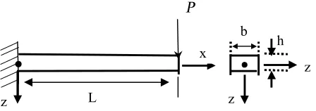
5. 1. Verification In order to verify the proposed model, results of the static bending and free vibration problems of a Bernoulli-Euler beam are compared with those presented in [13, 14], respectively. It is assumed that the beam is made of epoxy with the elastic modulus, Poisson’s ratio and the length scale parameter of E =1.44GPa, u=0.38 and l =17.6mm, respectively [13]. For the static bending problem, a cantilever beam is considered with a transverse force applied at the free end as shown in Figure 2 [13]. According to this figure, the loading and the geometry of the beam are
100
P = mN , b h/ =2 and L=20h with fz =0 , as in
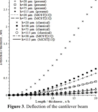
Equation 27. The deflection of the Bernouli-Euler cantilever beam under the transvere point load at the free end obtained by the present couple stress model, the modified couple stress theory (MCST) [13] and the classical theory are obtained and compared, as shown in Figure 3.
It is observed that values of the deflection predicted by the present model are identical to those of the modified couple stress theory developed in [13] and are smaller than those of the classical theory.
As mentioned earlier, the length scale parameter in the couple stress model developed by Hadjesfandiari is half of the length scale parameter in the modified couple stress theory. Hence, in order to obtain the numerical results in Figure 3, the length scale parameter in the modified couple stress theory is set equel to l=17.6mm
and in the present model is l =8.8mm.
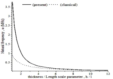
For the free vibration problem, variation of the natural frequency of vibration versus the ratio of thickness to length scale parameter of the beam obtained by the present model and the modified couple stress theory [14] are shown in Figure 4. It is observed from Figure 4 that results obtained by two methods are in excellent agreement.
Figure 2. A cantilevere beam
z L
x
P
b
z h
Figure 3. Deflection of the cantilever beam
Figure 4. Variation of the normalized natural frequency of the micro-beam
Figure 5. Variation of deflection of the clamped beam
Figure 6. Variation of deflection of the simply supported beam
5. 2 Case Studies In this part, values of deflection and natural frequency of the beam as derived in the previous sections are obtained. It is assumed that material properties and geometry of the beam are the same as those used in section 5.1. The beam is also assumed to be subjected to a constant lateral distributed load of intensity q=10N m/ and the mass density of the beam material is r=1.22 10´ 3kg m/ 3[16].
The ratio of the deflection to the thickness of the beam using the present couple stress model are obtained for three types of boundary conditions of clamped, simply supported and cantilever beams and shown in Figures 5, 6 and 7, respectively. It is found from these figures that the present couple stress model predicts lower values of deflection than the classical theory. It indicates that the stiffness of the beam predicted by the couple stress theory is higher in comparison with the classical theory. As the value of the beam thickness becomes closer to the length scale parameter, the difference between results of the present couple stress model and those of the classical theory increases. On the other hand, there is no significant difference between results obtained by two theories for higher values of the beam thickness. These results demonstrate that the micro-structural effect becomes important mainly when the characteristic size of the beam i.e. the value of thickness or the diameter of the cross-section approaches to the length scale parameter of the material of the beam. This is in agreement with experimental results as reported in the literature [1-5].
Figure 7. Variation of deflection of the cantilever beam
Figure 8.Variation of normalized deflection of the micro-beam
Figure 9. Variation of the first natural frequency of the clamped beam, present model versus classical theory
Figure 10. Variation of the first natural frequency of the simply supported beam, present model versus classical theory
Figure 11. Variation of the first natural frequency of the cantilever beam, present model versus classical theory
Figure 12. Variation of the normalized natural frequency of the micro-beam
The first natural frequency of the beam for three boundary conditions namely clamped, simply supported and cantilever beam are obtained using the present model and compared with results of the classical theory as shown in Figures 9, 10 and 11, respectively. It is observed in figures that the new couple stress model predicts higher values of natural frequency in comparison with the classical theory. It is also seen that the different between the results of the current model and those of the classical theory becomes significantly large when the value of beam thickness reaches the order of internal material length scale parameter. As the beam thickness increases, the difference between two theories is reduced.
TABLE 1. Deflection and frequency of vibration of the clamped-clamped beam
/
h l wmax/h w1
(
M Hz)
present 2 0.0973 3.1732
4 0.0078 3.9645
6 0.0014 5.0131
8 0.0004 6.1896
MCST 1 0.0973 3.1732
2 0.0078 3.9645
3 0.0014 5.0131
4 0.0004 6.1896
TABLE 2. Deflection and frequency of vibration of the simply supported beam
/
h l wmax/h w1(M H z)
present 2 0.4866 1.3998
4 0.0390 1.7489 6 0.0072 2.2115 8 0.0020 2.7305
MCST 1 0.4866 1.3998
2 0.0390 1.7489 3 0.0072 2.2115 4 0.0020 2.7305
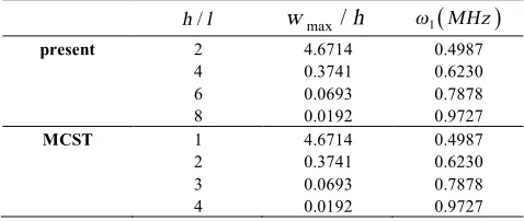
TABLE 3. Deflection and frequency of vibration of the cantilever beam
/
h l wmax/h w1
(
MHz)
present 2 4.6714 0.4987
4 0.3741 0.6230 6 0.0693 0.7878 8 0.0192 0.9727
MCST 1 4.6714 0.4987
2 0.3741 0.6230 3 0.0693 0.7878 4 0.0192 0.9727
Next, numerical results of the deflection and natural frequency of vibration obtained by the present model are compared with those predicted by the modified couple stress theory [13, 14]. Results obtained for three boundary conditions namely clamped-clamped, simply supported – simply supported and cantilever beam are shown in Tables 1, 2 and 3, respectively. In these tables, the length of the beam is assumed to be constant and equal to 300 10´ -6m. It is observed in these tables that values of deflection and natural frequency predicted by two theories are identical.
6. CONCLUSION
In this paper, a size-dependent formulation for the Bernoulli-Euler beam is presented based on the new model of couple stress theory developed by Hadjesfandiari. The constitutive equations developed by
this model consists of only one length scale parameter that is capable of describing the micro-structural effect in studying the mechanical behavior of structures. The governing equations and boundary conditions are obtained using the variational formulation and the Hamilton principle. The static bending and free vibration problems of the Bernoulli-Euler beam with three different boundary conditions are studied. Numerical results indicate that the present model predicts lower values of deflection of the beam and higher values of natural frequencies of vibration in comparison with the classical theory. It is also observed that as the thickness of the beam reduces and gets closer to the length scale parameter of the material, the difference between the present model and the classical theory increases. Furthermore, the difference between two theories reduces as the thickness of the beam increases.
7. REFERENCES
1. Fleck, N., Muller, G., Ashby, M. and Hutchinson, J., "Strain gradient plasticity: Theory and experiment", Acta Metallurgica
et Materialia, Vol. 42, No. 2, (1994), 475-487.
2. Ma, Q. and Clarke, D.R., "Size dependent hardness of silver single crystals " ,Journal of Materials Research, Vol. 10, No. 04, (1995), 853-863.
3. Stölken, J. and Evans, A., "A microbend test method for measuring the plasticity length scale", Acta Materialia, Vol. 46, No. 14, (1998), 5109-5115.
4. Chong, A. and Lam, D.C., "Strain gradient plasticity effect in indentation hardness of polymers", Journal of Materials
Research, Vol. 14, No. 10, (1999), 4103-4110.
5. McFarland, A.W. and Colton, J.S., "Role of material microstructure in plate stiffness with relevance to microcantilever sensors", Journal of Micromechanics and
Microengineering, Vol. 15, No. 5, (2005), 1060.
6. Mindlin, R. and Tiersten, H., "Effects of couple-stresses in linear elasticity", Archive for Rational Mechanics and Analysis, Vol. 11, No. 1, (1962), 415-448.
7. Toupin, R.A., "Elastic materials with couple-stresses", Archive
for Rational Mechanics and Analysis, Vol. 11, No. 1, (1962),
385-414.
8. Koiter, W., "Couple stresses in the theory of elasticity, i and ii", in Nederl. Akad. Wetensch. Proc. Ser. B. Vol .67, (1964), 17-29. 9. Anthoine, A., "Effect of couple-stresses on the elastic bending of beams", International Journal of Solids and Structures, Vol. 37, No. 7, (2000), 1003-1018.
10. Zhou, S. and Li, Z., "Length scales in the static and dynamic torsion of a circular cylindrical micro-bar", Journal of
Shandong University of Technology, Vol. 31, No. 5, (2001),
401-407.
11. Asghari, M., Kahrobaiyan, M., Rahaeifard, M. and Ahmadian, M., "Investigation of the size effects in timoshenko beams based on the couple stress theory", Archive of Applied Mechanics, Vol. 81, No. 7, (2011), 863-874.
12. Yang, F., Chong, A., Lam, D. and Tong, P., "Couple stress based strain gradient theory for elasticity", International Journal of
Solids and Structures, Vol. 39, No. 10, (2002), 2731-2743.
13. Park, S. and Gao, X., "Bernoulli–euler beam model based on a modified couple stress theory", Journal of Micromechanics and
14. Kong, S., Zhou, S., Nie, Z. and Wang, K ." The size-dependent , natural frequency of Bernoulli–Euler micro-beams",
International Journal of Engineering Science, Vol. 46, No. 5,
(2008), 427-437.
15. Asghari, M., Ahmadian, M., Kahrobaiyan, M. and Rahaeifard, M., "On the size-dependent behavior of functionally graded micro-beams", Materials & Design, Vol. 31, No. 5, (2010), 2324-2329.
16. Ma, H., Gao, X.-L. and Reddy, J., "A microstructure-dependent timoshenko beam model based on a modified couple stress theory", Journal of the Mechanics and Physics of Solids, Vol. 56, No. 12, (2008), 3379-3391.
17. Asghari, M., Rahaeifard, M., Kahrobaiyan, M. and Ahmadian, M., "The modified couple stress functionally graded timoshenko beam formulation", Materials & Design, Vol. 32, No. 3, (2011), 1435-1443.
18. Asghari, M., Kahrobaiyan, M. and Ahmadian, M., "A nonlinear timoshenko beam formulation based on the modified couple stress theory", International Journal of Engineering Science, Vol. 48, No. 12, (2010), 1749-1761.
19. Şimşek, M., Kocatürk, T. and Akbaş, Ş.D., "Static bending of a functionally graded microscale timoshenko beam based on the modified couple stress theory", Composite Structures, Vol. 95, No., (2013), 740-747.
20. Wanji, C., Chen, W. and Sze, K., "A model of composite laminated reddy beam based on a modified couple-stress theory", Composite Structures, Vol. 94, No. 8, (2012), 2599-2609.
21. Ke, L.-L., Wang, Y.-S., Yang, J. and Kitipornchai, S., "Nonlinear free vibration of size-dependent functionally graded microbeams", International Journal of Engineering Science, Vol. 50, No. 1, (2012), 256-267.
22. Wang, L., Xu, Y. and Ni, Q., "Size-dependent vibration analysis of three-dimensional cylindrical microbeams based on modified couple stress theory: A unified treatment", International
Journal of Engineering Science, Vol. 68, No., (2013), 1-10.
23. Ghayesh, M.H., Farokhi, H. and Amabili, M., "Nonlinear dynamics of a microscale beam based on the modified couple stress theory", Composites Part B: Engineering, Vol. 50, (2013), 318-324.
24. Hadjesfandiari, A.R. and Dargush, G.F., "Couple stress theory for solids", International Journal of Solids and Structures, Vol. 48, No. 18, (2011), 2496-2510.
25. Şimşek, M., "Dynamic analysis of an embedded microbeam carrying a moving microparticle based on the modified couple stress theory", International Journal of Engineering Science, Vol. 48, No. 12, (2010), 1721-1732.
26. Rao, S.S., "Vibration of continuous systems, John Wiley & Sons, (2007).
A Size-dependent Bernoulli-Euler Beam Formulation based on a New Model of
Couple Stress Theory
R. Akbari Alashti, A. H. Abolghasemi
Department of Mechanical Engineering, Babol University of Technology, Babol, Iran
P A P E R I N F O
Paper history:
Received 14 September 2013
Received in revised form 01 November 2013 Accepted 07 November 2013
Keywords:
Bernoulli-Euler Beam Couple Stress Theory Microstructural Effect Static Bending Free Vibration
هﺪﯿﮑﭼ
ﻂﺳﻮﺗهﺪﺷﻪﺋاراﺶﻨﺗﻞﭘﻮﮐﺪﯾﺪﺟلﺪﻣزاهدﺎﻔﺘﺳاﺎﺑ،ﻪﻟﺎﻘﻣﻦﯾارد
Hadjesfandiari
و
Dargush
ﻪﺘﺴﺑاويﺪﻨﺑلﻮﻣﺮﻓ،
ﺮﻠﯾواﺮﯿﺗﮏﯾياﺮﺑهدﺎﻣرﺎﺘﺧﺎﺳﺰﯾرهزاﺪﻧاﺮﺛا ﻪﺑ
-ﺖﺳاهﺪﺷهدادﻪﻌﺳﻮﺗﯽﻟﻮﻧﺮﺑ
.
لﺪﻣﻦﯾاردهﺪﻣآﺖﺳﺪﺑيرﺎﺘﺧﺎﺳﻂﺑاور
ﺮﯿﺛﺎﺗزاﯽﺷﺎﻧداﻮﻣﯽﮑﯿﻧﺎﮑﻣرﺎﺘﻓرﯽﻨﯿﺑﺶﯿﭘﻪﺑردﺎﻗاريرﻮﺌﺗﻦﯾاﻪﮐﺖﺳاهدﺎﻣﯽﻟﻮﻃسﺎﯿﻘﻣﺮﺘﻣارﺎﭘﮏﯾﻞﻣﺎﺷ،ﺪﯾﺪﺟ
رﺎﺘﺧﺎﺳﺰﯾرهزاﺪﻧا
دزﺎﺳﯽﻣ
.
يرﻮﺌﺗﺎﺑﻪﺴﯾﺎﻘﻣردلﺪﻣﻦﯾايﺎﻫﺖﯾﺰﻣزاﯽﮑﯾهدﺎﻣﯽﻟﻮﻃسﺎﯿﻘﻣﺮﺘﻣارﺎﭘﮏﯾﺎﻬﻨﺗﻦﺘﺷاد
ﺖﺳاهﺪﺷناﻮﻨﻋﺶﻨﺗﻞﭘﻮﮐﮏﯿﺳﻼﮐ
.
ﺮﻠﯾواﺮﯿﺗيزﺮﻣﻂﯾاﺮﺷوﻢﮐﺎﺣتﻻدﺎﻌﻣ
-
ﻞﺻاوﯽﺷدروشورزاهدﺎﻔﺘﺳاﺎﺑﯽﻟﻮﻧﺮﺑ
اﺮﯿﺗﮏﯾدازآشﺎﻌﺗراوﯽﮑﯿﺗﺎﺘﺳاﺶﻤﺧﻞﺋﺎﺴﻣوهﺪﻣآﺖﺳﺪﺑنﻮﺘﻠﯿﻤﻫ
ﺮﻠﯾو
-
ﺪﻧاهﺪﺷﻞﺣﻒﻠﺘﺨﻣيزﺮﻣﻂﯾاﺮﺷﺎﺑﯽﻟﻮﻧﺮﺑ
.
ﻪﺘﯿﺴﯿﺘﺳﻻايرﻮﺌﺗردهﺪﺷﯽﻨﯿﺑﺶﯿﭘراﺪﻘﻣزاﺮﺘﻤﮐﺪﯾﺪﺟلﺪﻣردهﺪﺷﯽﻨﯿﺑﺶﯿﭘﺰﯿﺧراﺪﻘﻣﻪﮐﺪﻨﻫدﯽﻣنﺎﺸﻧيدﺪﻋﺞﯾﺎﺘﻧ
ﺪﺷﺎﺑﯽﻣﮏﯿﺳﻼﮐ
.
ﺪﺷﺎﺑﯽﻣﮏﯿﺳﻼﮐيرﻮﺌﺗزا ﺮﺗﻻﺎﺑيرﻮﺌﺗﻦﯾا ردهﺪﻣآﺖﺳﺪﺑدازآشﺎﻌﺗرايﺎﻫﺲﻧﺎﮐﺮﻓﻦﯿﻨﭽﻤﻫ
.
ﺗ
ﻪﺑﺮﯿﺗﺖﻣﺎﺨﺿراﺪﻘﻣنﺪﺷﮏﯾدﺰﻧﺎﺑﮏﯿﺳﻼﮐيرﻮﺌﺗ وﺮﺿﺎﺣﺶﻨﺗﻞﭘﻮﮐيرﻮﺌﺗزاهﺪﻣآﺖﺳﺪﺑيﺎﻬﺑاﻮﺟﻦﯿﺑتوﺎﻔ
دﻮﺷﯽﻣدﺎﯾز،هدﺎﻣﯽﻟﻮﻃسﺎﯿﻘﻣﺮﺘﻣارﺎﭘ
.
doi: 10.5829/idosi.ije.2014.27.06c.14