19
International Journal of Engineering and Management Research, Volume-3, Issue-3, June 2013
ISSN No.: 2250-0758
Pages: 19-23
www.ijemr.net
Design of High Performance Floating Point SRT Divider Using Divisor
and Partial Remainders Estimates
Saifur Rahman1, Ahmad Hesham Ansri2
1
Department of Electronics Communication Engineering, Integral University, Lucknow, INDIA.
2
Department of Electronics Communication Engineering, Integral University, Lucknow, INDIA.
ABSTRACT
SRT dividers are common in modern floating point units. Higher division performance is achieved by retiring more quotient bits in each cycle. Previous research has shown that realistic stages are limited to radix-2 and radix-4. Higher radix dividers are therefore formed by a combination of low-radix stages. In this paper, we present an analysis of the n-bit divider and Comparative analysis of different dividers in case of delays and performance. We show the performance and area results for a wide variety of divider architectures and implementations. We conclude that divider performance is only weakly sensitive to reasonable choices of architecture but significantly improved by restoring and non restoring techniques.
Keywords--- VLSI, SRT Division, n-bit Divider, Delays.
I. INTRODUCTION
Arithmetic circuits have received relatively little attention from the verification community, except by those using methods based on theorem proving, e.g., [6]. This inattention is due to two main reasons. First, many perceive that arithmetic circuit design is fairly straightforward—the same implementation techniques have been used for years, and designers are confident of their ability to detect errors using conventional simulation. Intel’s recent experience with its Pentium floating point divider [5] has exposed the error in this thinking. There are many places one can make mistakes in designing these circuits, some of which may be very hard to detect with the limited number of cases that can be tested by simulation. Second, these circuits are especially challenging for methods based on ordered Binary Decision Diagrams (BDDs), the most popular alternative to theorem proving [3]. The BDDs representing the outputs of a multiplier grow exponentially with the word size [2], making them impractical for word sizes much beyond 16 bits. A similar result has been shown for representing the outputs of a divider [7]. On the other hand, the outputs of simpler units
such as adders, subtractors, and comparators are represented very efficiently with BDDs.
In this paper, we demonstrate that restoring and non restoring based dividers can be usefully applied to complex arithmetic circuits. Even though it is not feasible to verify the overall circuit functionality, just verifying one iteration can uncover many possible design errors. We demonstrate this by showing the desired behavior for one iteration of radix4 SRT division [1], as used in the Pentium divider, can be specified and verified using BDDs. This verification will detect incorrect entries in the “PD” table, used to generate a quotient digit on each division step, such as occurred in the Pentium, as well as other potentially subtle design errors. Going on beyond verification, we show that a correct PD table can be generated automatically. Our method extends the correction method described by Madre and Coudert [4] to handle logic blocks with larger numbers of inputs and outputs.
20
methods, such as simulation, as well as to the cost of any design errors that could be missed by these less comprehensive approaches.
The Pentium FDIV problem provides a clear illustration for the potential value of opportunistic verification. Compared to the $475 million charge that Intel took against its 1994 revenues to replace defective Pentium chips, one can easily justify applying verification tools to a number of subsystems, including many parts of the floating point unit.
II.
SRT DIVISION
A. Definitions:
In this analysis, the input operands are assumed to be represented in a normalized floating point format with n bit significands in sign-and-magnitude representation. The algorithms presented here are applied only to the magnitudes of the significands of the input operands. Techniques for computing the resulting exponent and sign are straightforward.
The most common format found in modern computers is the IEEE 754 standard for binary floating point arithmetic. This standard defines single and double precision formats, where n=24 for single precision and n=53 for double precision. The significand consists of a normalized quantity,with an explicit or implicit leading bit to the left of the implied binary point, and the magnitude of the significand is in the range [1,2). However, to simplify the presentation, this analysis assumes fractional quotients normalized to the range [0.5,1).
The quotient is defined to comprise k radix-r digits with
r=2b k=n/b
where a division algorithm that retires b bits of quotient in each iteration is said to be a radix-r algorithm. Such an algorithm requires k iterations to compute the final n bit result and thus has a latency of k cycles. The cycle time of the divider is defined as the maximum time to compute one iteration of the algorithm. Depending upon the implementation, this may or may not be the same as the cycle time of the processor.
The following recurrence is used in every iteration of the SRT algorithm:
rP0 = dividend
Pj+1 = rPj - qj+1divisor
where Pj is the partial remainder, or residual, at
iteration j. In each iteration, one digit of the quotient is determined by the quotient-digit selection function:
qj+1 = SEL (rPj ; divisor)
The final quotient after k iterations is then
B. Divider Parameters:
1) Choice of Radix:The fundamental method of decreasing the overall latency (in machine cycles) of the algorithm is to increase the radix r of the algorithm, typically chosen to be a power of 2. However, this latency reduction does not come for free. As the radix increases, the quotient-digit selection becomes more complicated, which may increase the cycle time. Moreover, the generation of all required divisor multiples may become impractical for higher radices. Oberman [8] shows that the delay of quotient selection tables increases linearly with increasing radix, while the area increases quadratically. While prescaling of the input operands [9] reduces table complexity at the expense of additional latency, nevertheless the difficulty in generating all of the required divisor multiples for radix 8 and higher limits practical divider implementations to radix 2 and radix 4.
2) Choice of Quotient Digit Set:
For a given choice of radix r, some range of digits is decided upon for the allowed values of the quotient in each iteration. The simplest case is where, for radix r, there are exactly r allowed values of the quotient. However, to increase the performance of the algorithm, a redundant digit set is used. This allows a quotient digit to be selected based upon an approximation of the partial remainder, permitting the use of a redundant remainder representation as discussed in the next section. Small errors in the quotient due to the remainder approximation are corrected in later iterations. Such a digit set is composed of symmetric signed-digit consecutive integers, where the maximum digit is a. The digit set is made redundant by having more than r digits in the set. By using a larger number of allowed quotient digits, the complexity and latency of the quotient selection function is reduced. However, choosing a smaller number of allowed digits for the quotient simplifies the generation of the multiple of the divisor. Specifically, for radix 2, the digit set is {-1; 0; 1}. For radix 4, there are two typical choices for the digit set: minimally redundant {-2;-1; 0; 1; 2} and maximally redundant {-3; -2; -1; 0; 1; 2; 3}. The quotient selection logic for a maximally-redundant radix 4 digit set is about 20% faster and 50% smaller than for a minimally redundant digit set [10]. However, maximally-redundant radix 4 requires the computation of the 3x divisor multiple, which typically requires extra initial delay and area.
3) Choice of Remainder Representation:
carry-propagate-21
adder, increasing the cycle time. Therefore, the partial remainder is typically stored in redundant form so that a fast carry-free adder, such as a carry-save adder (CSA), can be used in the partial remainder calculation.
Figure 1: SRT divider block diagram
III.
PREVIOUS APROCH
In recent years computer applications have increased in their computational complexity. High-speed floating-point hardware is a requirement in many VLSI systems to meet these increasing demands. An important component of the floating point unit is the divider. There are many methods for designing division hardware, including quadratically converging algorithms, such as Newton–Raphson, and linear converging algorithms, the most common of which is SRT [15]. SRT division computes a quotient one digit at a time, with an iteration time independent of the operand length.
The theory of SRT division is discussed thoroughly in Atkins [10]. Several SRT implementations have been reported, including radix 2 dividers by Knowles [14], radix 4 by Birman [16], radix 8 by Fandrianto [13], and radix 16 by Carter [12]. SRT dividers with simplified quotient-digit selection using operand range restriction have been presented. Harris [17] discusses detailed algorithmic and circuit tradeoffs in SRT divider design.
There are many performance and area tradeoffs when designing an SRT divider. One metric for comparison of different designs is the minimum required truncations of the divisor and partial remainder for quotient-digit selection. Atkins [10] provide such analyzes of the divisor and partial remainder precisions required for quotient-digit selection. Burgess and Williams [11] present in more detail allowable truncations for divisors and both carry-save and borrow-save partial remainders. However, a more detailed comparison of quotient-digit selection complexity between different designs requires more information than input precision. This paper analyzes in detail the effects of algorithm radix, redundancy, divisor and partial remainder precision, and truncation error on the complexity of the resulting table. Complexity is measured by the number of product terms in the final logic equations, and the delay and area of standardcell implementations of the tables. These metrics are obtained by an automated design flow using the specifications for the quotient-digit selection table as input, a Gray-coded PLA as an intermediate representation, and an LSI Logic 500 K standard-cell implementation as the output. This
paper also examines the effects of additional techniques such as table folding and longer external carry-assimilating adders on table complexity. Using the methodology presented, it is possible to automatically generate optimized high radix quotient-digit selection tables.
IV. SIMULATION RESULTS
In case of 16-bit divider we took 16- bit dividend is “0000000010101010” and 16- bit divisor is “0000000000000010” then the reminder is “0000000000000000”. In fig 2 we have shown the simulation result fir 16-bit divider.
Figure 2: Simulation Result for 16 Bit Divider
In case of 8-bit divider we took 8- bit dividend is “10101010” and 8- bit divisor is “00000010” then the reminder is “00000000”. In fig 3 we have shown the simulation result fir 8-bit divider.
Figure 3: Simulation Result for 8 Bit Divider
22
Figure 4: Simulation Result for 4 Bit Divider
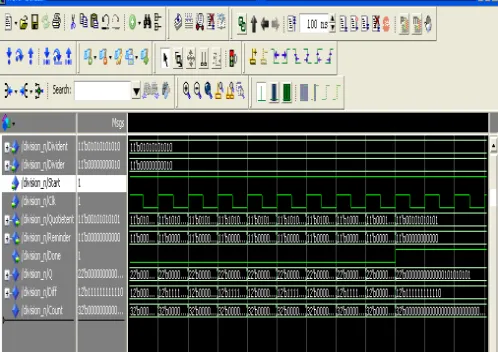
In case of n-bit divider we took as a example 11- bit dividend is “01010101010” and 11- bit divisor is “00000000010” then the reminder is “00000000000”. In fig 5 we have shown the simulation result fir n-bit divider.
Figure 5: Simulation Result for n Bit Divider
V. CONCLUSION
We have shown how to divide n- bits by implement n-Bit divider. In this work we also compare Results of 16-bit divider, 8-16-bit Divider, 4-16-bit Divider, and n-Bit divider. And we found that the logic delay and rout delays are almost same. So in place of use 16-bit divider, 8-bit Divider, 4-bit Divider… e.t.c. we can use n-bit divider. It will be reduce the cost, low power consumption and less area. In modern VLSI implementations, these tradeoffs directly affect the time and space required since custom designs use only the required number of bits.
In 4-bit divider the logic delay is 5.753 ns and route delay is 1.755 ns then the total delay for 4-bit divider is 7.508 ns. In case of 8-bit divider the logic delay is 5.753 ns and route delay is 1.332 ns then the total delay for 8-bit divider is 7.085 ns. In case of 16-bit divider the logic delay
is 5.753 ns and route delay is 1.566 ns then the total delay for 16-bit divider is 7.319 ns. In case of n-bit divider the logic delay is 6.302 ns and route delay is 2.601 ns then the total delay for n-bit divider is 8.903 ns. If we look simply then we can say that the total delay of n-bit divider is greater than rest of Dividers but we can not decide which divider is required is every where. So that if we required three different dividers like 4, 8, 16-bit dividers then total delay will be 21.912 ns. That is why we use n-bit divider in place of these different dividers. Then the delay will be just 8.903 ns. This delay is clearly less then from these all these dividers. Here we are talking about just three dividers but practically we need more bit dividers and more dividers.
So if we did not take n-bit divider then we has to design many more different dividers for different bit. They will defiantly take more time, area, power and also cost. But in VLSI we have to save all of these. Then the result is n-bit divider is taking less power, less area and reduce the cost.
TABLE I RESULT COMPARISON
Divider
Logic Delay
(ns)
Route Delay
(ns)
Total Delay
(ns)
4-Bit Divider 5.753 1.755
7.508
8- Bit Divider 5.753 1.332 7.085
16- Bit Divider 5.753 1.566 7.319
n- Bit Divider 6.302 2.601 8.903
REFERENCES
[1] D. E. Atkins, “Higherradix division using estimates of the divisor and partial remainder,” IEEE Transactions on Computers, Vol. C17, No. 10 (October, 1968), pp. 925– 934.
[2] R. E. Bryant, “On the complexity of VLSI implementations and graph representations of Boolean functions with application to integer multiplication,” IEEE Transactions on Computers, Vol. 40, No. 2 (February, 1991), pp. 205–213.
[3] R. E. Bryant, “Symbolic Boolean manipulation with ordered binary decision diagrams,” ACM Computing Surveys, Vol. 24, No. 3 (September, 1992), pp. 293–318. [4] J.C. Madre, and O. Coudert, “Automating the diagnosis and rectification of design errors in PRIAM,” International Conference on ComputerAided Design, 1989, pp. 30–33. [5] H. P. Sharangpani, M. L. Barton, “Statistical analysis of floating point flaw in the Pentium processor(1994),” Intel Technical Report, Nov. 30, 1994.
23
[7] I. Wegener, “Optimal lower bounds on the depth of polynomialsize threshold circuits for some arithmetic functions,” Information Processing Letters, Vol. 46, pp. 85–87.
[8] S. F. Oberman, Design Issues in High Performance Floating Point Arithmetic Units, Ph.D. thesis, Stanford University, Nov. 1996.
[9] M. D. Ercegovac and T. Lang, “Simple radix-4 division with operands scaling,” IEEE Trans. Computers, vol. 39, no. 9, pp. 1204–1208, Sept. 1990.
[10] D. E. Atkins, “Higher-radix division using estimates of the divisor and partial remainders,” IEEE Trans. Comput.,, vol. C-17, Oct. 1968.
[11] N. Burgess and T. Williams, “Choices of operand truncation in the SRT division algorithm,” IEEE Trans. Comput., vol. 44, pp. 933–937, July 1995.
[12] T. Carter and J. Robertson, “Radix-16 signed-digit division,” IEEE Trans. Comput, vol. 39, pp. 1243–1433, Dec. 1990.
[13] J. Fandrianto, “Algorithm for high-speed shared radix 8 division and radix 8 square root,” in Proc. 9th IEEE Symp. Computer Arithmetic, July 1989, pp. 68–75.
[14] S. Knowles, “Arithmetic processor design for the T9000 transputer,” ASPAAI-2, 1991.
[15] S. F. Oberman and M. J. Flynn, “Division algorithms and implementations,” IEEE Trans. Comput., vol. 46, pp. 833–854, Aug. 1997.
[16] M. Birman, A. Samuels, G. Chu, T. Chuk, L. Hu, J. McLeod, and J. Barnes, “Developing the WTL 3170/3171 Sparc floating-point coprocessors,” IEEE Micro, vol. 10, no. 1, pp. 55–63, Feb. 1990.