Single and Twisted Blades Digital Simulation and
Dynamic Analysis
A. Benretem
Electromechanical Engineering Laboratory, Badji-Mokhtar Annaba University P.O. Box12, 23000, Annaba Algeria
Email ID : [email protected]
N. Zerari
Electromechanical Engineering Laboratory, Badji-Mokhtar Annaba University P.O. Box12, 23000, Annaba Algeria
Email ID : [email protected]
Abstract – This work represents a comparative study of a numerical simulation of frequencies and fundamental modes of flapping vibration, drag and torsion of the two blades of a small wind turbine, a single one and another with optimum blade design. The objective of this study is to understand the behavior of two types of blades subjected to various canvassing. The results reveal that the various canvassing and maximum displacements are located at the end of the two blades; in fact, the results show that a single blade has higher frequencies than twisted one but does not undergo large displacements in comparison to twisted blade.
Keywords – Small Wind Turbine, Blade, Fundamental
Modes, Simulation, Aerodynamics, Displacement, Frequency.
I.
I
NTRODUCTIONA wind turbine is a machine for converting wind kinetic energy into mechanical one by conversion of forces from aerodynamic origin into engine torque. However, the aerodynamic forces are also not the only stress to be applied on a wind turbine during operating. We also must consider the origin of inertial forces (gravity, centrifugal force, etc ...), number of previous work in this subject have been achieved, studies in references [1,2] were referred to the modal analysis of small wind turbine blades. A blade can be modeled as a fixed beam; the various canvassing applied impose its verification by statics study, dynamic and frequency. The 3D model created from different tables used for the application of various loads [2]. A finite elements’ model was developed by Ahlström [3] Patricio Lillo and Curran Crawford [4] for the dynamic responses simulation of horizontal axis wind turbines. The aerodynamic model used for the care of the airflow field on the blades is the model of the blade blade / time, and the non-stationary aerodynamics and modeling of dynamic stall, he used a Dynastall subroutine. The comparison results obtained by simulation with experimentation measurements have shown that the model can predict aerodynamic response in case of normal and extreme loads. [5] Patricio Lillo and Curran Crawford [4] study elastic origin forces applied to the blade such as the strains and stresses. And the fluid-structure interactions that are presented in references [5, 6]. In this article we will present the different results obtained by numerical simulation for two blade types from the various geometric parameters of the latter [7], explaining each case.
II.
A
PPROACHThe work consists of two stages:
1. Modeling of the two blades (single blade paddle and with optimal design);
2. Static review of the fundamental modes and frequencies for both models of the proposed blades.
III.
M
ODELING AS
MALLW
INDT
URBINE ON ANH
ORIZONTALA
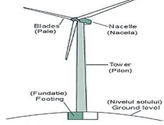
XISThe figure below shows a small wind turbine with a rotor facing into the wind with three blades with a radius of 3 m, the platform is supported by a tubular steel mast of 25 meters high. The study of flexible or rigid structures’ behavior such as wind turbine blades generally uses resolutions based on finite element type model. It is used to record, analyze and evaluate the frequencies and modes of oscillation and to optimize these elements structure. The latter allow a detailed description of blades’ movement interacting with the wind, taking into account a large number of structure modes.
Fig. 1. The small wind turbine description
IV.
B
LADEM
ODELLING4.1 Blade Overview
In [7] a study was conducted to analyze the aerodynamic behavior of two types of blades; a twisted blade with variable rope and another single, in order to show the effect of some geometrical characteristics of the blade on its behavior while operating.
4.1.1 Simple Pale at a Constant Rope [7] - Rope: C (r) = 0.2120 m;
4.1.2 Optimal Form Blade [7]
- The distribution of the rope length C (r) as a function of the radius r;
- The distribution of the twist angle β (r) as a function of the radius r;
- Profile using NACA 0012; - Blade material: Aluminum alloy; 4.2 Blade Modeling
Solidworks is a solid modeling software. It enables the design of three-dimensional objects and visualization in realistic form, this is CAD software (Computer Aided Design), it is used by industrial field professionals.
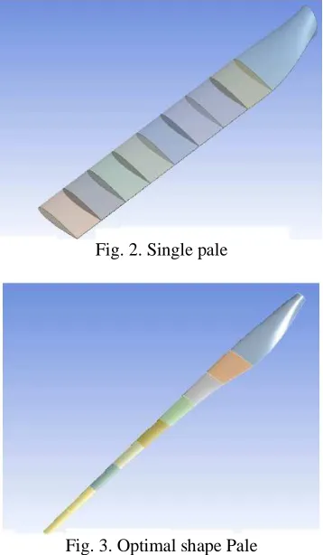
With Solidworks, we can model the two small blades that we used in the aerodynamic study, an optimum shape blade and another simple, as shown in the two figures below were divided both blades in nine blade elements. 4.2.1 Establishment of an Aerofoil
A simplistic approach is to consider a wind turbine blade looks and behaves as an airplane wing. For the construction of a blade we created nine parallel planes equidistant of 298 mm. coordinates (x, y) were recovered of the points characterizing the contour of a wing cross section NACA 0012 [8, 9] profile type, by using geometrical data in the reference [7] we have succeeded in modeling the two variants of the blades shown in Fig (2) and (3).
Fig. 2. Single pale
Fig. 3. Optimal shape Pale
The assembly of the three blades gives us the wind rotor shown in Fig (4) and (5)
Fig. 4. Wind rotor of three simple blades
Fig. 5. Optimal form wind rotor
V.
D
IGITALS
IMULATIONR
ESULTS5.1 Static Analysis "Distorted Modal"
Apart from the influence of aerodynamic forces on the blade, a static comparative study between two types of blades, where we discover the geometry effect on the blade behavior, and knowledge of the most sensitive areas on the blade. Three distinct movements are considered in the case of a wind turbine blade: flapping, drag and torsion. We will present the canvassing to which both blades variants are subjected. The three-dimensional representation of the specific deformation of both blade wind turbines types is more explicit by this comparative study. The simulation results show the influence of the blade model choice and its geometry, by the following figures that illustrate the first five modes of vibration and the natural frequency of each type of blade. The first visualization of these modes shows the big difference between the stressed areas by the deformations irrespective of the flapping, and the drag torque for both types of blades.
5.1.1 1st Flapping Mode
The figures below illustrate the first flapping mode of the two blades.
Fig. 7. 1st Flapping mode of an optimal shape blade.
5.1.2 2nd Beat Mode
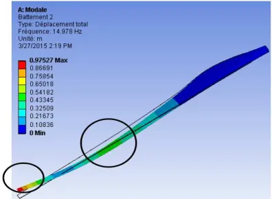
The Fig (8) and (9) represent the 2nd flapping vibration mode of the blade.
Fig. 8. 2nd Flapping mode of a simple blade
Fig. 9. 2nd Flapping mode of an optimal shape blade.
The first display of these modes shows that the tip of the blade is the most stressed by deformations, the most loaded area after the end is the middle of the blade in both types but the deformation of the twisted blade is more important than a single blade, for the frequencies it is the opposite.
5.1.3 3rd Flapping Mode
Fig (10) and (11) give the 3rd beating mode of vibration of two blades. The first observation in the figures below, which shows that the affected areas are the same in both cases, but with different intensities.
Fig. 10. 3rd flapping mode of a simple blade
Fig. 11. 3rd flapping mode of a blade with an optimal shape
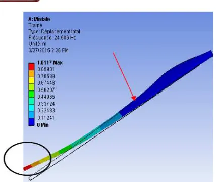
5.1.4 Drag
Fig (12) and (13) represent the drag mode, noting that the same areas in both blades are affected, but always with different intensities.
Fig. 13. The drag of an optimal shape blade.
5.1.5 Torsion
Fig (14), (15) below represents the first torsional mode of the two different blades. The blade end is the first affected part in both blades, the same areas in the two blades have undergone torsion, but according to the results obtained, the twisted blade is the most stressed
Fig. 14. The torsion of a single blade
Fig. 15. The twist of an optimal shape blade.
5.2 Results of the Natural Frequencies
From the numerical simulation and the preceding figures, we summarized the first ten frequencies of the two types of blades in Fig (16). Noticing that the frequency of a single blade is greater than that of a variable-string twisted blade that the figure clearly shows (16).
Fig. 16. The first ten frequencies of the two blade types
VI.
C
ONCLUSIONThis study allowed us to determine the frequencies and fundamental modes of vibration of two types of blades in flapping, drag and torsion. Overall, the results show that the various stresses and maximum displacements are located at the ends of two blades. We revealed that the displacements are very important in the variable-string twisted blade comparing to that of a simple blade but with lower frequencies comparing to the simple blade.
R
EFERENCES[1] N. Surendra. J.Yang,, « Using Modal Analysis for DetectingCracks in Wind Turbine Blade »; Vibrant Technology, Inc., Scotts Valley, California; Sound & Vibration/may. 2011.
[2] M. Nadjah, M. Khechana, L. Laiche, T. Ouksel,C. Mahfoudi, « Etude de l’hélice d’une éolienne de 5 kW » Revue des Energies Renouvelables CISM’08 Oum El Bouaghi 257 - 264 .2008.
www.cder.dz/download/CISM08_23.pdf
[3] A. Ahlström, ‘Aeroelastic Simulation of Wind Turbine
Dynamics’, Doctoral Thesis, Royal Institute of
Technology, Stockholm,Sweden,2005
www.elforsk.se/Global/.../Vindsim_AAhlstrom.pd
[4] P.Lillo_,C.Crawfordy, « Analysis of Fatigue Loads of
Wind Turbine Blades Subject to Cold Weather Conditions Using a Finite Element Model, University of
Victoria, Victoria, BC, Canada 49th AIAA Aerospace Sciences Meeting including the New Horizons Forum and Aerospace Exposition, 4, Orlando, Florida, 7, January, 2011. www.enu.kz/repository/2011/AIAA-2011-262.pdf
[5] A. Bekhti O. Guerri; « Simulation de l’écoulement
autour d’un profil de pale d’éolienne », Revue des
Energies Renouvelables SMEE’10 BouIsmail Tipaza;49– 56.2010. www.cder.dz/download/smee2010_6.pdf
[7] N. Zerari, A. Benretem « Assessment wind field in the
region of Annaba East Algeria with an aerodynamic
analysis for installation a small wind
turbines MECHANIKA. 2014 Volume 20(6): 582-589 2014.
[8] L.Sheldah, E. Robert, C. Paul, « Aerodynamic
Characteristics of Seven Symmetrical Airfoil Sections Through 180-Degree Angle of Attack for Use in Aerodynamic Analysis of Vertical Axis Wind Turbines »,
Sandia National Laboratories, Albuquerque. USA .1981 [9] UIUC Airfoil Data Site UIUC Airfoil Data Site - UIUC
Applied Aerodynamics Group-
selig.ae.illinois.edu/ads/coord_database.html
A
UTHOR'
SP
ROFILEAbdelouahab Benretem After graduating from the
Faculty of Electrical Engineering of the University of Science and Technology, Annaba, Algeria, in 1983, he obtained the Magister (Dr. Eng.) degree in 1986 and the PhD. degree in 2005 on centrifugal pumps working in mixture liquid- solid and the professor degree in 2011. He is currently a president Electromechanical council department, directing and supervise a research group on renewable energy. He is teacher-cum-researcher at University of Annaba and LGELM laboratory. His technical fields of interest are Turbomachinery and renewable energy.
Naziha Zerari received the Magister degree in University of Boumerdes
Algeria. She is currently pursuing the Doctorate degree on renewable energy at the electromechanical laboratory, Annaba University-Algeria. Currently, she is an Assistant professor at University of Boumerdes since 2014, where she gives courses on mechanics; hydraulic and industrial systems. Her experience is in the product industrial systems and the renewable energy systems.