Available Online at www.ijpret.com 468
INTERNATIONAL JOURNAL OF PURE AND
APPLIED RESEARCH IN ENGINEERING AND
TECHNOLOGY
A PATH FOR HORIZING YOUR INNOVATIVE WORK
SYNTHESIS AND IMPLEMENTATION ON FPGA BASED PLC
SONALI KHAIRNAR
Student of Master’s of Engineering From E &TC Dept. of Siddhant Collage of Engineering, Pune
Accepted Date: 05/03/2015; Published Date: 01/05/2015
\
Abstract: Programmable logic controller (PLCs) has become an indispensable control unit in the Industrial control field. But the performance of traditional PLC will be restricted by the length of ladder diagram and the operation speed of the microprocessor. It is difficult to adapt to the requirements of high-speed control in modern industry. Therefore, figuring out a way to realize high-speed control becomes more and more important. Field programmable gate array (FPGA) has characteristics of supporting high-speed parallel execution and hardware configuration. Realizing the function of PLC by it can greatly improve the execution speed of control logic and this is an important way to solve the current problems of PLC. The performance of programmable logic controllers is often constrained by the microprocessor and the real-time firmware of the controller. Field programmable gate arrays (FPGAs) are an attractive potential implementation medium for high-speed control because of their fast and parallel execution and programmable nature. Ladder Diagrams are a standard graphical programming method for industrial controllers, but compilers from Ladder Diagrams to FPGA hardware do not yet exist. So this Project is the conversation of Ladder to VHDL programming in order to meet the FPGA advantages. The project is to implement Batch Processing Application on FPGA based PLC and to have a comparative study on results when implemented on it. The Batch Processing Application the contents are mixed in the user defined proportion taking into consideration of various parameters like the weight of the content used, time each hopper of the content will open in order to pour into the mixer hopper. Then at what temperature and pressure the content is mixed is to be maintained. The FPGA based PLC plays important role in opening and closing of the solenoid valve of each hopper, if the timing delay occurs then mixer is not mixed in the proper proportion. In order to do so the application is implemented on PLC and FPGA based PLC controlled, and the comparison is done related to it. PLC, based on FPGA, can greatly improve the speed of logic control.
Keywords: FPGA, Spartan 3, PLC
Corresponding Author: MS. SONALI KHAIRNAR
Access Online On:
www.ijpret.com
How to Cite This Article:
Available Online at www.ijpret.com 469
INTRODUCTION
Programmable logic controllers (PLCs) are a main stay for industrial process control and automation applications. They are low-cost, reliable, easy to use, and have been proven with years of successful operation. Their discrete analog and digital I/O features and ability to close control loops in the hundreds-of-hertz range meet many application needs. Unfortunately, not all applications easily fit into these constraints. Many new approaches to machine building have necessitated higher-performance controllers with innovative architectures. FPGA combines the real-time computing power of a computer with the reliability and flexibility of a field-programmable gate array (FPGA). The FPGA portion of the RIO architecture enables three core benefits over traditional control systems: high-performance parallel processing, custom hardware flexibility, and hardware logic reliability. Programmable logic controllers (PLCs) are a main stay for industrial process control and automation applications. They are low-cost, reliable, easy to use, and have been proven with years of successful operation. Their discrete analog and digital I/O features and ability to close control loops in the hundreds-of-hertz range meet many application needs. Unfortunately, not all applications easily fit into these constraints. Many new approaches to machine building have necessitated higher-performance controllers with innovative architectures. NI Compact RIO is a PAC that combines the real-time computing power of a computer with the reliability and flexibility of a field-programmable gate array (FPGA). The FPGA portion of the RIO architecture enables three core benefits over traditional control systems: high-performance parallel processing, custom hardware flexibility, and hardware logic reliability.
Programmable logic controllers (PLCs) are a main stay for industrial process control and automation applications. They are low-cost, reliable, easy to use, and have been proven with years of successful operation. Their discrete analog and digital I/O features and ability to close control loops in the hundreds-of-hertz range meet many application needs. Unfortunately, not all applications easily fit into these constraints. Many new approaches to machine building have necessitated higher-performance controllers with innovative architectures. NI Compact RIO is a PAC that combines the real-time computing power of a computer with the reliability and flexibility of a field-programmable gate array (FPGA). The FPGA portion of the RIO architecture enables three core benefits over traditional control systems: high-performance parallel processing, custom hardware flexibility, and hardware logic reliability.
I. LITERATURE SURVEY
Available Online at www.ijpret.com 470 Today for its parallel execution mechanism and
Reconfigurable hardware structure [1]. Programmable Logic Controller (PLC) is a user friendly, microprocessor based specialized computer that carries out control functions of many types and that of different levels of complexities [2]. Its purpose is to monitor crucial process parameters and adjust process operations accordingly. The PLC will operate any system that has output devices that go on/off (known as discrete or digital outputs) or vary pr oporti onat el y (known as analog outputs). The first PLC system evolved from conventional computers in the late 1960s and early 1970s.
Though the late 1970s, improvements were made in the PLC programs to make them somewhat more user friendly. PLCs are also referred to as Programmable Controllers or
Sequential Processors (i.e. devices that handle step by step execution of operations) that are widely used in commercial and industrial applications.
B. FPGA TECHNOLOGY
Available Online at www.ijpret.com 471 parallel execution, FPGAs are able to perform control algorithms with loop rates up to hundreds of kilohertz, with room left over to handle multiple axis control algorithms, data communication for a human machine interface (HMI), or interaction with a host microprocessor. Moreover, with the reconfigurable nature of FPGAs, you can adjust the control algorithm whenever necessary.
A PLC designed using FPGA technology results in better solution providing following advantages:
(a) Short product development cycle
Due to the use of standard HDLs and runs directly in silicon, engineers can try out various types of implementation and hence, product development time is reduced significantly.
(b) Flexibility
Design engineers (PLC manufactures) can easily upgrade the Micro PLC designs. For example some feature or instructions could be added in the existing designs, simply by changing HDL and configuring the same FPGA chip for the modified designed of Micro PLC.
(c) Accuracy
This design provides parallel concurrent execution of blocks in hardware, hence provides better performance and accuracy as compared to conventional PLC.
(d) Very High Speed Performance
These design is based on FPGA that performs all tasks in parallel, hence execution of the proposed system design is very fast compare to conventional PLC as the later performs all the operations sequentially.
(e) Cost Effective and Compactness
Available Online at www.ijpret.com 472 II. Praposed method
A. Method
A programmable logic controller, PLC or programmable controller is a digital computer used for automation of typically industrial electromechanical processes, such as control of machinery on factory assembly lines, amusement rides, or light fixtures. PLCs are used in many industries and machines.
Early PLCs were designed to replace relay logic systems. These PLCs were programmed in "ladder logic", which strongly resembles a schematic diagram of relay logic. This program notation was chosen to reduce training demands for the existing technicians. Other early PLCs used a form of instruction list programming, based on a stack-based logic solver.
Modern PLCs can be programmed in a variety of ways, from the relay-derived ladder logic to programming languages such as specially adapted dialects of BASIC and C. Another method is State Logic, a very high-level programming language designed to program PLCs based on state transition diagrams.
Available Online at www.ijpret.com 473 A PLC program is generally executed repeatedly as long as the controlled system is running. The status of physical input points is copied to an area of memory accessible to the processor, sometimes called the "I/O Image Table". The program is then run from its first instruction rung down to the last rung. It takes some time for the processor of the PLC to evaluate all the rungs and update the I/O image table with the status of outputs.
Field Programmable Gate Arrays(FPGAs), offers an alternative solution for complex processing. They offer optimum performance, reduced power consumption, parallel processing ,and the flexibility associated to hardware. This fact has leaded some PLC manufacturers to design a new class of PLC based on FPGAs instead of on sequential processors .The LD network is widely used method for describing control algorithms. This method has been inherited from relay control systems. Contacts and coils represent logic dependencies between signals and function blocks. The LD network processing speed can be increased by parallel execution of the logic operation in programmable hardware. Transforming logic dependencies into combinatorial logic allows increasing performance several orders of magnitude.
The majority of PLC manufacturers use the ladder logic diagram programming language to program their programmable logic controllers (PLCs). Some manufacturers prefer using logic gate circuits or Boolean expressions to program their PLCs.
For example.
The function of an XOR gate is simulated in the electric circuit displayed in Figure ( ). Notice that the lamp will be on if one switch is open while the other switch is closed.
Figure ( ) displays a ladder logic diagram that performs the function of an XOR gate. When I:0/0 is on, I:0/1 must be off and vice versa in order to turn on output O:0/0. When either Pushbutton #1 or Pushbutton #2 is pressed, the output is ON. When both pushbuttons are pressed, output is OFF.
Creating logic gate circuits from ladder diagrams
The first step in this process to find the Boolean expression that represents the ladder logic diagram. You can then draw the logic gate circuit using the Boolean expression.
Available Online at www.ijpret.com 474 For e.g.
Entity contact _ n0 is
por t (
i : in std_ logic ;
a : in std_ logic;
o : out std_ logic) ;
end contact_no ;
architecture arch of contact_no s
begin
o <= a and i ;
Available Online at www.ijpret.com 475
III. EXPERIMENTAL STUDY
Batch Mixing Application
The actual software is to be written in Ladder Programming Language. The mixer is designed to take in two liquids from the input pumps, stir and heat them to a mixture before collecting the mixture at the output pumps.
All operation instructions come from the programmable logic controller to either switch ON/OFF any component of the mixer subsystem depending on its state or the state of another component. The mixer operates by taking in two different liquids from the input pumps one after the other and then performing a heating and stirring operation on this liquid within the vessel. The mixture collected from the output pump and the whole process begins again. The program starts with the opening of PUMP1 to pour the first liquid into the vessel. A Timer is also set and with this
Timer we can vary the quantity of the first liquid which we want to put into the vessel. This is made possible with a flow meter because the product of flow rate and time gives an exact amount of the liquid we wish to pour in first from PUMP1.
When the Timer completes the timing operation, it will Deactivate PUMP1 and also open PUMP2 to pour in the second liquid until the containing vessel is FULL. The hilevel sensor usually indicates that the tank is FULL and at the same time stops PUMP2.It also starts the action of both the MIXER and the HEATER. The MIXER and HEATER must operate together at the same time in an AND operation i.e. starting one also starts the other and stopping one also stops the other. A temperature sensor is used to stop the
HEATER and the MIXER. This sensor is active HIGH and usually starts PUMP3 in order to let out the mixture from the containing vessel. An empty containing vessel is usually indicated by the low-level sensor which also starts PUMP1 in order to repeat the mixing process all over again.
Available Online at www.ijpret.com 476
IV. RESULT AND DISCUSSION
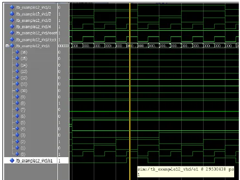
Simulation Results
Available Online at www.ijpret.com 477
V. CONCLUSION
This paper is describes only concept of a new implementation approach to FPGA based PLC. This design is limited to only four digital inputs and outputs. To overcome the performance limitation of microprocessor based PLC, the suggested approach provides better result. The idea described here is best suitable for small-scale application where the need is limited number of instructions at reasonable cost, which also offer best performance, high speed and compact design approach.
For implementation of the suggested solution, some studies on implementation of control programs into logic description in form of Hardware Description Language (HDL) have been carried out. Hence, it becomes necessary for the user of proposed design to have knowledge of design tools to translate, integrate and implement the logic circuit in FPGA.
In Future scope we can create a basic software which will direct create the Ladder programs to VHDL program, and be able to download on FPGA directly.
REFERENCES
1. Positite .M. “Omron Beginner’s guide to PLC", www.mikrocontrol.co.yu, Serbia, 2003, pp 1-17
2. Barber Andy, Industrial Mixing, www.foodtechcompare.com, USA,
3. Bryan .L.A, “Programmable Logic Controllers Theory and implementation”, second edition, Industrial Text Company, USA, 1997, pp 4-104
4. Wikipedia, “Industrial Mixer, www.wikipedia.com/industrial mixer, USA,
5. Dileep Krishnan, “Intelligent Traffic Light Control using PLC", Cochin University of Science and Technology, India, www.seminarpapers.com,
6. Gray Richard, “Ladder Logic Programming" Transtronics Inc, USA, www.xtronics.com
7. Xilinx Inc. 2013. MicroBlaze Soft Processor Core. Retrieved January 23, 2013, from
Available Online at www.ijpret.com 478 9. M. Ikeshita, Y. Takeda, H. Murakoshi, N. Funakubo, and I. Miyazawa, An application of FPGA to high speed programmable controller development of the conversion program from SFC to Verilog in Proc. 7th IEEE Int l Conf Emerging Technologies and Factory Automation ETFA 99, vol. 2, 1999, pp. 1386 1390
10. D. Gawali, V.K. Sharma, FPGA Based Micro-PLC Design Approach, in International Conferenc on Advances in Computing, Control, \& Telecommunication Technologies, 2009. ACT '09, Trivandrum, India, December 2009, pp. 660-663.
11. YASAR BIRBIR,SELCUK NOGAY, "PLC-based Monitoring and Control system for a 3-phase
induction Motor", Marmara University, Technical Education Faculty, Turkey,
www.csanyigroup.com