Encrypted Audio Signal
Transmission in 5G Compatible
Downlink Multiuser Pattern Division Multiple Access
(PDMA) Wireless Communication System
Mst. Afrin Naher*, Shaikh Enayet Ullah
Department of Applied Physics and Electronic Engineering, University of Rajshahi, Rajshahi, Bangladesh
Abstract
In this paper, we have made performance evaluative study for the 5G compatible downlink Pattern Division Multiple Access (PDMA) scheme implemented wireless communication system on encrypted audio signal transmission in AWGN and Rayleigh fading channel. The simulated system under consideration incorporates modern channel coding (Polar and (3,2)SPC) and different low order digital modulation (4-QAM, QPSK and DQPSK) schemes. With implementation of G[2,3]PDMA pattern matrix for three users and considering total transmitted power of 40 Watt, 50%, 30% and 20% of totaltransmitted power have been assigned to first, second and third users and additionally phase shifting factors have been applied in power scaled transmitted signals of second and third users to resolve ambiguity in individual data separation. On consideration of encrypted audio signal transmission, it is observable from MATLAB based simulation study that the (3,2)SPC channel encoded power domain PDMA simulated system is very much robust and effective in retrieving transmitted audio data with achieving a BER of 10-3 at 21 Eb/No.
Keywords
PDMA, Polar, (3,2) SPC, G[2,3]PDMA pattern matrix, AWGN and Rayleigh fading channel, Bit error rate(BER),Normalized SNR(Eb/No)
1. Introduction
In present scenario of telecommunication sector, it is noticeable that an anticipated 1000-fold increase in mobile data traffic over the next decade and the explosion of new services and applications pose great challenges in existing orthogonal multiple access (OMA)-based 4G networks. Dai and et al., firstly introduced the principle of the complexity-constrained capacity-achieving NOMA design. Then a non-orthogonal pattern division multiple access (PDMA) scheme was proposed to meet up the exponentially growing demand of mobile users for computing and information application services. Their results demonstrated that the PDMA could be a promising multiple access technology with low latency, low signaling overhead and massive connectivity support for 5G [1]. At [2], Tang and et al., analyzed the theory performance of uplink PDMA and derived the exact closed-form expressions for outage probability (OP) in the Rayleigh fading channel and also evaluated the OPs of each user with different pattern and
* Corresponding author:
[email protected] (Afrin Naher) Published online at http://journal.sapub.org/jwnc
Copyright©2018The Author(s).PublishedbyScientific&AcademicPublishing This work is licensed under the Creative Commons Attribution International License (CC BY). http://creativecommons.org/licenses/by/4.0/
that are assigned to users in a same Resource Element (RE). Maric and et al., presented a method of an algebraic construction of short quasi orthogonal PDMA patterns that were ideally suited for use in NOMA PDMA. In their work, the authors showed that within each family it was possible to construct patterns with different weights (level of diversity). Using link level simulations, they established the performance of their sequences, and compared them with PN sequences as well as with sequences in the other PDMA literature [4]. At [5], Vinod and Jose presented a 5G technique called Pattern Division Multiple Access (PDMA) using Compressed Sensing Algorithm for communication systems and defined resource group using PDMA patterns with reference to either time or frequency for data transmission. The authors demanded that an improved execution in terms of Spectral efficiency, bit error rate and uplink-downlink performance was obtained through implementation of Compressive Sampling Matching Pursuit (CoSaMP) algorithm. In [6], Jiang and et al., proposed, a joint transmitter and receiver design for pattern division multiple access (PDMA) utilizing power allocation to improve the overall sum rate and beam allocation to enhance the access connectivity by pattern mapping at the transmitter and a spatial filter to suppress the inter-beam interference caused by beam-domain multiplexing, and successive interference cancellation to remove the intra-beam interference caused by power-domain multiplexing by hybrid detection at the receiver. The authors proposed a PDMA joint design approach to optimize pattern mapping based on both the power domain and beam domain. Their simulation results showed that the proposed PDMA approach outperformed s the orthogonal multiple access and power-domain non-orthogonal multiple access approaches even without any optimization of pattern mapping and the optimization of beam allocation yielded a significant performance improvement than the optimization of power allocation.
2. Review of Encryption and Signal
Processing Techniques
In this paper, both physical layer security and signal processing techniques have been implemented. A brief review of each technique is outlined below:
2.1. Hybrid Chaotic Maps based Encryption
In modern communication systems, the major goal is oriented to the security and the encryption methods are very much important to maintain integrity, authentication and privacy of information from unauthorized people. In Hybrid Chaotic Maps based Encryption technique, both Henon chaotic system and logistic chaotic maps are used. The Henon random map is described by the discrete Equations as:
(1a) (1b) Where, a and b are external parameter. From Equation (1b), we can write
(1c) Substituting the value of from Equation (1c) in Equation (1b), we get
(2)
Using Equation (2), the initial values, X(0), and external parameter values, a and b are set at: X(0)=0.1, X(0)=0.2, and X(0)=0.3, a=1.4, a=1.5 and a=1.6, b=0.3, b=0.4 and b=0.5 for user#1,user#2 and user#3 respectively. As the number of ultimately estimated 8bit integer values from audio signal of each user is 8192, the no. of variables presented in Equation (2) from generated Henon Chaotic map is 8192. Equation (2) is applicable for n=1,2,3,4………8191.
The X(0)=0.1, X(0)=0.2 and X(0)=0.3 are the values of variable for user #1, user #2 and user #3 at n=0. The first generated encrypted keys K1 are obtained from transforming Henon Chaotic maps into 8-bit integer values using the relation: K1(n)= mod(round(X(n)),256) (3)
Where, = 12345678, = 65431234 and = 87654321 for user#1, user#2 and user#3 The one-dimensional Logistic chaotic map is given by (4)
Where, r is the control parameters with its value is in the interval of 3.57 < r 4. The initial values X(0)=0.1, X(0)=0.2 and X(0)=0.3, r=3.57, r=3.65 and r=4.00 are assigned for user #1, user #2 and user #3. The second generated encrypted keys K2 are obtained from transforming Logistic Chaotic maps of Equation (4) into 8-bit integer values using the relation K2(n)=mod(round(X(n)),256) (5)
where,= 23456789, =78923456 and = 98765432 for user #1, user #2 and user #3, If A(n) and B(n) are the 81921 sized 8 bit integer values obtained from the text messages for near and far user and executing binary bitwise XOR operation, we can write Afirst(n)=A(n)K1(n) (6)
Bfirst(n)=B(n)K1(n) (7)
Ahybrid=Afirst(n)K2(n) (8)
Bhybrid=Bfirst(n)K2(n) (9)
Where, the symbol is indicative bitwise XOR operation. Equation (8) and Equation (9) represent Hybrid chaotic maps
based encrypted audio signals for three users [7].
n n 2 1
n 1 aX Y
X
n 1
n bX
Y
1 n n bX
Y n
Y
1 n n 2 1
n 1 aX bX
X
) X (1 * X * r
2.2. Polar Channel Coding and Decoding
Polar codes represent an emerging class of error-correcting codes with power to approach the capacity of a discrete memoryless channel. In non symmetric form of polar coding with code length N(=8), the 1 8 matrix sized binary source block u= (u1, u2, … , uN) consists of K(=4),
non-frozen information bits (0/1) and N–K frozen bits (typically considered as 0) assigning at {u4, u6, u7, u8} and {u1, u2, u3, u5} respectively. In execution of bit reversal operation, the rearranged 1 8 matrix sized binary source block, =( 1, 2, … , N) would contain non-frozen
information bits at { 7, 6, 4, 8} instead of { 4, 6, 7, 8} and frozen bits at { 1, 5, 3, 2} instead of { 1, 2, 3, 5}.
The polar encoded code word x in binary format(0/1) with code rate R= K/N can be obtained as follows:
X= (10) where, round function is used to get the nearest integer value and mode operation provides each elemental value of x to (0,1), F23 is the 8 8 sized matrix produced from the third
Kronecker power of 2 2 sized matrix F2 presented as:
(11) This matrix is called the kernel matrix [8].
In polar decoding, the received polar encoded code word in binary format (0/1) is BPSK modulated producing (0/1) into (+1,-1) viz. {+1,-1}. It is passed through AWGN channel and noise contaminated with a random noise variable having zero mean and variance . The AWGN channel’s output with its components { can be represented as:
(12) The transition probability for AWGN channel is given by (13) The received AWGN channel LLR is calculated using the following relation [9]:
(14) The 18 matrix sized noisy channel LLR, undergoes bit-reversed operation forming a new modified noisy channel LLR, with its components . At the non frozen bit locations, the estimated values are used to compute information bits using successive cancellation polar decoding technique [10].
2.3. (3,2)SPC Channel Coding
In SPC channel coding, the transmitted binary bits are rearranged into very small code words consisting of merely two consecutive bits. In such coding, (3,2)SPC code is used with addition of a single parity bit to the message u =[u0, u1]
so that the elements of the resulting code word x = [x0, x1, x2]
are given by x0 = u0, x1 = u1 and x2 = u0u1 [11]
where, denotes the sum over GF (2).
2.4. Designing of PDMA Pattern and Signal detection
In our present study, a 23 PDMA pattern matrix has been used where 3 users are multiplexed on two resource elements (REs). The PDMA pattern in such case can be written as:
(15) Taking PDMA pattern , transmitted data of 3 users are mapped onto two REs. The transmission signal on these REs can be expressed as:
(16)
where, sj is the transmission signal on the jth RE, and wk is the
modulation symbol of the kth user
Unlike orthogonal transmission, transmission signal on each RE is linear combination of multiple modulation symbols:
(17) To resolve ambiguity in proper detection of users own data, power scaling and phase shifting are introduced in PDMA pattern matrix. Specifically, before two users symbols are mixed, a power scaling factor and a phase shifting factor are applied:
(18) where, is the power scaling factor and is the phase shifting factor. In this present study, merely, phase shifting factor has been applied to data of user #2 and user #3. As each user is equipped with a single antenna and base station is equipped with two antennas, the fading channel matrix is 2
3 sized and it is represented as:
(19) The PDMA equivalent channel response matrix H can be written as:
H=
= = (20)
u
u
u
u
u
u
u
u
u
u
u
u
u
u
u
u
u
u
u
u
mod(u*F23,2
1 1 0 1 2 F
x
~
x
~
n
~
2y ~ } y ~ , y ~ , y ~ , y ~ , y ~ , y ~ , y ~ , y ~ 8 7 6 5 4 3 2 1 n ~ x ~ y ~
2 2
2 ) 1 ~ ( exp 2 1 ) ~ ~ ( y x y P
2 2 2 2 2 llr y ~ 2 2 ) 1 y ~ ( 2 ) 1 y ~ ( exp log y ~ llr y ~ llry
~~
} llr8 y ~ ~ ..., llr3 y ~ ~ , llr2 y ~ ~ , llr1 y ~ ~ {}
y
~
~
,
y
~
~
y
~
~
,
y
~
~
{
llr4 llr6, llr7 llr8 1 0 1 0 1 1 G[2,3]PDMA
PDMA ] 3 , 2 [
G
3 2 1 2 1 w w w 1 0 1 0 1 1 s s 21 1 βw
j e w β
s
23 22 21 13 12 11 CH h h h h h h H PDMA ] 3 , 2 [ CH G H 23 22 21 13 12 11 h h h h h h 1 0 1 0 1 1 23 21 12 11 0 0 h h h h s1= w1 +w2
where, has been considered to represent element-wise product of two matrices. In PDMA equivalent channel response matrix H, the channel coefficients of first, second and third columns are applicable to user #1, user #2 and user #3. As signal transmitted from base station from two antennas use different resource (frequency), the signal received at user #1 from second antenna of base station is neglected. The signal received at the user #1, user #2 and user #3 can be written as:
z1= h11(w1 +w2) (21)
z2= h12(w1 +w2) (22)
z3= h23(w1 +w3) (23)
From equation (21) through equation (23), it is observable that in every cases, another user’s data are treating as interference which are needed to be eliminated. Primarily, digitally modulated complex symbol vectors for three users,
are scaled in power such that the average power for each user is made to unity. If P be the total transmitted power and 1, 2 and 3 are the power scaling
factors (0.5,0.3 and 0.2) of three users,2 and 3 are phase
scaling factors for user #2 and user #3, the power and phase scaled signal vector of the three users can be written as:
(24)
On applying OFDM modulation to each data vector presented in Equation (24), the transmitted signal vectors for three users w1, w2 and w3 are produced. In receiving section
of each user, the AWGN noise contaminated Rayleigh faded signal is undergone OFDM demodulation. The OFDM demodulated signal vectors w10, w20 and w30 are channel
equalized and can be written as: w11=(h11)-1w10
= + (25) w22=(h12)-1 w20
= + (26) w33=(h23)-1w30
= + (27) In equation (25) through (27), , and are the detected power scaled complex modulated symbol vectors for three users. These signal vectors are assumed to have average power of unity which are further rescaled to retrieve original signal vectors. In equations 25, 26 and 27, the , and are the interference terms, denoting W={w(1), w(2), w(3) and w(4)} is the power scaled (unity average power) signal alphabet of
4QAM/QPSK/DQPSK and using ML decoding, the detected interfering complex symbols contained in interference term for user #1, user #2 and user #3 can be obtained from:
(28)
(29)
(30) The detected power scaled complex symbols
for three users can be written as:
= (w11- )/ (31) = (w22- )/ (32) = (w33- )/ (33) On multiplying Equation (31) through Equation (33) with normalization factor, Ξ(= ), the original complex digitally modulated data symbols for user #1, user #2 and user #3 are achieved viz [12,13].
(34) (35) (36)
3. System Description
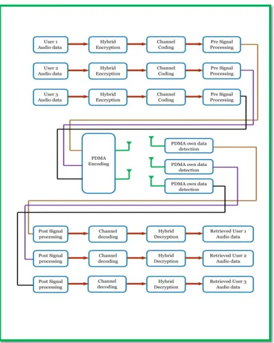
The block diagram of the 5G compatible downlink Pattern Division Multiple Access (PDMA) scheme implemented wireless communication system model in simplified form has been presented in Figure 1. In such simulated model, segments of different audio signals for three different users will be processed. The extracted binary data from audio signal for each user are undergone double encryption using hybrid chaotic maps based physical layer security scheme. The encrypted data are channel encoded and fed into pre signal processing section where interleaving, digitally modulation, power scaling with phase insertion (in case of signals for user 2 and user 3), serial to parallel conversion, OFDM modulation and parallel to serial conversion is done.
The pre processed signals are PDMA encoded prior to transmission from each of the two transmitting antennas of Base station.
3 wˆ and 2 wˆ , 1 wˆ 3 2 jφ 3 3 3 jφ 2 2 2 1 1 1e
w
ˆ
Pβ
w
ˆˆ
e
w
ˆ
Pβ
w
ˆˆ
w
ˆ
Pβ
w
ˆˆ
1 1 1w
ˆ
Pβ
jφ222 2wˆ e
Pβ
1 1 1wˆ
Pβ jφ2
22 2wˆ e
Pβ
1 1 1
w
ˆ
Pβ
jφ333 3wˆ e
Pβ
1 1
w
ˆ
w
ˆ
22w
ˆ
332
jφ 22 2wˆ e
Pβ Pβ1wˆ11 Pβ1wˆ11
3 2 1,w andw
w
2
jφ (k) 1 11 1 11 2
(k)
ˆ
w arg min w Pβ w Pβ w e ,
k 1, 2,3, 4 w W
2
jφ (k)
2 22 1 2 22
(k)
ˆ w arg min w Pβ w Pβ w e ,
k 1, 2,3, 4 w W
3
jφ (k)
3 33 1 3 33 (k)
ˆ w arg min w Pβ w Pβ w e ,
k 1, 2,3, 4 w W
3 2
1,wˆˆ and wˆˆ
wˆˆ
1
w
ˆˆ
jφ21 2
w
e
Pβ
( Pβ1)2
w
ˆˆ
Pβ1w2 ( Pβ e )2
jφ 2
3
w
ˆˆ
Pβ1w3 ( Pβ e )3 jφ 3 2
1w
ˆˆˆ
w
ˆˆ
1
2w
ˆˆˆ
w
ˆˆ
2
3Figure 1. Block diagram of 5 G Compatible downlink Multiuser PDMA Wireless Communication System
The signal transmitted from two transmitting antennas are in different resource elements such that the frequency of transmitted carrier is different. In receiving section of each user, own transmitted signal is detected along with other user’s signal transmitted in identical resource element considered as interference. The received signal is processed for interference reduction and subsequently sent up to the post signal processing section where serial to parallel conversion, OFDM demodulation parallel to serial conversion, power rescaled with phase removing, digitally demodulation and deinterleaving occur. The post processed signals are channel decoded, hybrid decrypted and eventually audio signal of each user is retrieved.
4. Results and Discussion
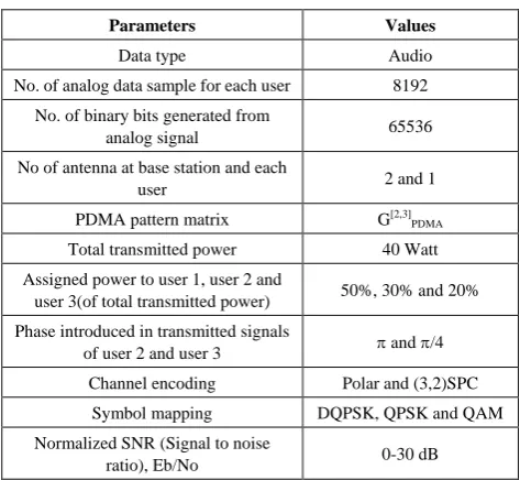
Table 1. Summary of the simulated model parameters
Parameters Values
Data type Audio
No. of analog data sample for each user 8192
No. of binary bits generated from
analog signal 65536 No of antenna at base station and each
user 2 and 1
PDMA pattern matrix G[2,3] PDMA
Total transmitted power 40 Watt Assigned power to user 1, user 2 and
user 3(of total transmitted power) 50%, 30% and 20%
Phase introduced in transmitted signals
of user 2 and user 3 and /4 Channel encoding Polar and (3,2)SPC
Symbol mapping DQPSK, QPSK and QAM Normalized SNR (Signal to noise
ratio), Eb/No 0-30 dB
It is quite obvious from graphical illustrations presented in Figure 2 that the performance of the simulated system with
implemented (3,2)SPC channel coding is very much well defined for user #1. In such case, the simulated system shows better performance in 4-QAM and worst performance in DQPSK digital modulation. On critical observation of simulation curve, it is seen that for a typically assumed Eb/No value of 5 dB, the estimated BER values are 0.1644, 0.2215 and 0.3436 which are indicative of system performance improvement of 1.2947 dB and 3.2015 dB in case of 4-QAM as compared to QPSK and DQPSK digital modulations. At 10% BER, requirement of Eb/No with DQPSK digital modulation is found to have value of 15.25 dB. It is reduced to 2.25 dB and 4.5 dB in case of QPSK and 4-QAM digital modulations respectively.
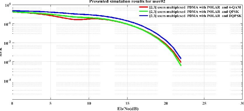
From Figure 3 for user #2, it is seen that the requirement of Eb/No with DQPSK digital modulation is 15.5 dB at 10% BER. It is reduced to 2.5 dB and 4.5 dB in case of QPSK and 4-QAM digital modulations respectively. For a SNR value of 5 dB (as previously considered), the estimated BER values are 0.2224, 0.2861 and 0.4079 which are indicative of (3,2) SPC channel encoded system performance improvement of 1.0938 dB and 2.6342 dB in case of 4-QAM as compared to QPSK and DQPSK digital modulations.
Figure 2. BER performance of (3,2)SPC channel encoded downlink Pattern Division Multiple Access (PDMA) scheme implemented 5G compatible wireless communication system for user #1 under utilization of various digital modulation schemes
Figure 4. BER performance of (3, 2)SPC channel encoded downlink Pattern Division Multiple Access (PDMA) scheme implemented 5G compatible wireless communication system for user #3 under utilization of various digital modulation schemes
Figure 5. BER performance of POLAR channel encoded downlink Pattern Division Multiple Access (PDMA) scheme implemented 5G compatible wireless communication system for user #1 under utilization of various digital modulation schemes
Figure 7. BER performance of POLAR channel encoded downlink Pattern Division Multiple Access (PDMA) scheme implemented 5G compatible wireless communication system for user #3 under utilization of various digital modulation schemes
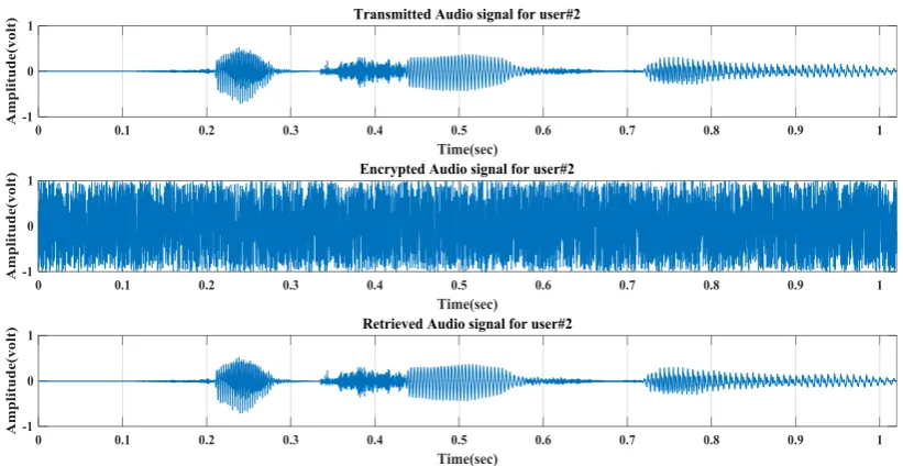
Figure 8. Transmitted, Encrypted and Retrieved audio signals at Eb/No value of 30 dB for user#1
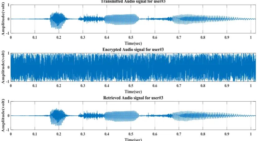
Figure 10. Transmitted, Encrypted and Retrieved audio signals at Eb/No value of 30 dB for user#3
It is quite obvious in graphical illustrations presented in Figure 4 for user #3 that the performance of the (3,2)SPC channel encoded system is not well discriminated in case of DQPSK and 4-QAM over a wide range of Eb/No values (10 dB-26 dB). In this case, it is found that the simulated system shows comparatively better performance in QPSK digital modulation.
From Figure 5 for user #1, it is noticeable that the Polar channel encoded simulated system shows better performance in 4-QAM and worst performance in DQPSK digital modulation. For a typically assumed Eb/No value of 5 dB, the estimated BER values are 0.1788, 0.2465 and 0.333 which are indicative of system performance improvements of 1.3945 dB and 2.7008 dB in case of 4-QAM as compared to QPSK and DQPSK digital modulations. It is also observable that the system performance in 4-QAM digital modulations coincides with that for QPSK over Eb/No values (10 dB-22 dB).
In Figure 6 for user #2, it is seen that the Polar channel encoded simulated system shows worst performance in DQPSK digital modulation. The system performance in case of 4-QAM and QPSK digital modulations is not well discriminated from each other for Eb/No region (10.5 dB-21 dB).
In Figure 7 for user #3, as low power is assigned to user #3, the Polar channel encoded system performance degrades. On critical observation on the presented graphs, the system performance in case of QPSK digital modulation seems to be better.
The graphical illustrations presented in Figure 8 through 10 are clearly indicative of retrieving audio signals uniquely at Eb/No value of 30 dB for 3 users. The presented graphs also ratified that the encrypted audio signal for each of 3 users is not understandable.
5. Conclusions
In this paper, the performance of 5G compatible downlink multiuser PDMA wireless communication system has been investigated on secured audio signal transmission with utilization of various channel coding techniques. In all cases, the proposed simulated system out performs in 4-QAM and shows worst performance in DQPSK digital modulation. The simulation results show that the implementation of (3, 2) SPC channel coding technique with utilization of 4-QAM digital modulation scheme ratifies the robustness of 5G compatible downlink multiuser PDMA wireless communication system in retrieving audio signal transmitted over noisy and Rayleigh fading channels.
REFERENCES
[1] Xiaoming Dai; Zhenyu Zhang; Baoming Bai; Shanzhi Chen; Shaohui Sun, 2018: Pattern Division Multiple Access: A New Multiple Access Technology for 5G, IEEE Wireless Communications, Volume: 25, Issue: 2, pp: 54 – 60. [2] Wanwei Tang; Shaoli Kang; Bin Ren; Xinwei Yue; Xiurong
Zhang, 2018, Uplink pattern division multiple access in 5G systems, IET Communications, Volume: 12, Issue: 9, pp. 1029 – 1034.
[3] Kai Li; Jue Wang; Chen Xu; 2018: Design of PDMA Communication System Based on OQAM-OFDM, In proceeding of 2nd IEEE Advanced Information Management, Communicates, Electronic and Automation Control Conference (IMCEC), pp.2098 – 2104.
[5] Kavya Vinod; Renu Jose, 2018: Compressed Sensing Algorithm for Pattern Division Multiple Access (PDMA) in 5G Radio Networks, In proceeding of International CET Conference on Control, Communication, and Computing (IC4), pp.224 – 229.
[6] Yanxiang Jiang; Peng Li; Zhiguo Ding; Fuchun Zheng; Miaoli Ma; Xiaohu You, 2018: Joint Transmitter and Receiver Design for Pattern Division Multiple Access, IEEE Transactions on Mobile Computing, pp.1-11.
[7] Ammar M. Raheema, Sattar B. Sadkhan, and Sinan M. Abdul Sattar, 2018: Design and Implementation of Speech Encryption Based on Hybrid Chaotic Maps, In proceeding of the International Conference on Engineering Technologies and their Applications (ICETA), pp.112 – 117.
[8] Kai Niu, Kai Chen, Jiaru Lin, and Q. T. Zhang, 2014: Polar Codes: Primary Concepts and Practical Decoding Algorithms, IEEE Communications Magazine, vol. 52, issue 7, pp.192-203.
[9] Navneet Kaur and Arvinder Pal Singh Kalsi, 2016: Implementation of Polar Codes over AWGN and Binary Symmetric Channel, Indian Journal of Science and Technology, vol. 9(19), pp.1-4.
[10] Polar-Codes-Software-Matlab, https://github.com/Spartak0s/ Polar-Codes-Software-Matlab-/blob/master/main.m. [11] Giorgio M. Vitetta, Desmond P. Taylor, Giulio Colavolpe,
Fabrizio Pancaldi and Philippa A. Martin, 2013: Wireless Communications Algorithmic Techniques, John Wiley and Sons Ltd, United Kingdom.
[12] Shanzhi Chen, Bin Ren, Qiubin Gao, Shaoli Kang, Shaohui Sun, and Kai Niu, 2016: Pattern Division Multiple Access (PDMA) -A Novel Non-orthogonal Multiple Access for 5G Radio Networks, IEEE Transactions on Vehicular Technology, 2016.