Available Online at www.ijpret.com 86
INTERNATIONAL JOURNAL OF PURE AND
APPLIED RESEARCH IN ENGINEERING AND
TECHNOLOGY
A PATH FOR HORIZING YOUR INNOVATIVE WORK
ZIGBEE BASED COLOR TRANSFORMATION FOR BLIND IN WIRELESS NETWORK
MR. SERVESH GUPTA, DR. PROF. D. T. INGOLE, PROF. M. D. INGOLE
Department of Digital Electronics, Prof. Ram Meghe Institute of Technology & Research, Badnera, Amravati.
Accepted Date: 15/03/2016; Published Date: 01/05/2016
\
Abstract:This system tries to identify the possibility of converting colour in accordance with sound using Zigbee technology in wireless sensor network. This system deals with the emotion of blind person who tries to explore different colours which he could not see or they have lost the possibility of seeing it. This paper focuses on the most widely used transceiver standard in Wireless Sensor Networks, a ZigBee technology. ZigBee over IEEE 802.15.4 defines specifications for low data rate WPAN (LR-WPAN) to support low power monitoring and controlling devices. This paper presents a Zigbee wireless standard, IEEE802.15.4 specification, ZigBee device types, the protocol stack architecture and its applications. This system stimulation of one sensory pathway leads to automatic experience in second pathway. This portable wireless system will be capable of detecting colour transforming it into sound using ZigBee network and use of annunciation system with the help of IC apr9600.
Keywords: Synesthesia, Colour, PIC18F8542, Sound, Blind, Zigbee, Wireless Sensor Network.
Corresponding Author: MR. SERVESH GUPTA
Access Online On:
www.ijpret.com
How to Cite This Article:
Servesh Gupta, IJPRET, 2016; Volume 4 (9): 86-96
Available Online at www.ijpret.com 87
INTRODUCTION
With the development of network and communication technology, the WSN has solved the inconvenience into people’s life. WSN has good functions of data collection, transmission, and processing. It has many advantages com-pared to traditional wired network. This system uses Zigbee network for transmission of detected colors. Synesthesia is a condition in which one sense (for example, hearing) is simultaneously perceived as if by one or more additional senses such as sight. Another form of synesthesia joins objects such as letters, shapes, numbers or people’s names with a sensory perception such as smell, color or flavor. The word synesthesia comes from two Greek words, syn (together) and aesthesis (perception). Therefore, synesthesia literally means “joined perception.”
Estimates for the number of people with synesthesia range from 1 in 200 to 1 in 100,000. Synesthesia can involve any of the senses. The most common form, colored letters and numbers, occurs when someone always sees a certain color in response to a certain letter of the alphabet or number. For example, a synesthete (a person with synesthesia) might see the word “plane” as mint green or the number “4” as dark brown. Synesthetic perceptions are specific to each person. Different people with synesthesia almost always disagree on their perceptions. In other words, if one synesthete thinks that the letter “q” is colored blue, another synesthete might see “q” as orange. Synestetes tend to be, Women: in the U.S., studies show that three times as many women as men have synesthesia; in the U.K., eight times as many women have been reported to have it. The reason for this difference is not known. Left handed: synesthetes are more likely to be left-handed than the general population. Neurologically normal: synesthetes are of normal (or possibly above average) intelligence and standard neurological exams are normal. In the same family: synesthesia appears to be inherited in some fashion; it seems to be a dominant trait and it may be on the X-chromosome.
II. PROPOSED METHOD
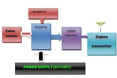
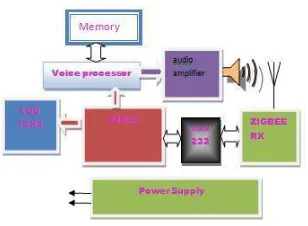
The basic block diagram for the Transmitter and Receiver system is as shown in the figure 1. It consists of the following modules:
Colour Sensor
PIC18f8542
Zigbee Transmitter
Available Online at www.ijpret.com 88 Power supply
LCD Display
Voice Processor
Fig. 1. Synthesia Block Diagram
Circuit is powered by a battery of 12v=1Amp, as project we require +5V regulated power supply with maximum cur-rent rating 500mA. To step down the mains 230V A.C. step down transformer is required. Step down transformer gives out well regulated +5V output, output current capability of 100mA. Microcontroller PIC18f8520 is the heart of the circuitry. It is the main block which takes the inputs and processes it and gives the output. All the other blocks work in accordance with the microcontroller. MAX RS232: The Serial communication is used to transfer data between the zigbee device and the microcontroller. MAX RS232 is used for this purpose. ZIGBEE TRANSNMITTER: It transmits the signal which is connected to RS 232 interface. It works on 2.4 GHz frequency with the serial interface. ZIGBEE RECEIVER: It receives the signal which is connected to RS 232 interface. It works on 2.4 GHz frequency with the serial interface. MAX RS232: The Serial communication is used to transfer data between the mobile device and the microcontroller. MAX RS232 is used for this purpose. Microcontroller PIC18F4520 is the heart of the circuitry. It is the main block which takes the inputs and processes it and gives the output. All the other blocks work in accordance with the microcontroller. LCD display can be interfaced with microcontroller to read the output directly. In our project we use a two line LCD display with 16 characters each. VOICE PROCESSOR (AP333A3) device offers true single-chip voice recording, non-volatile storage, and playback capability for 11minutes.
A. Colour sensors
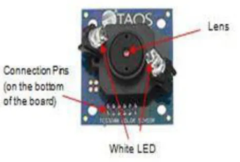
Available Online at www.ijpret.com 89 Both the ColorPAL and TCS 3200 colour sensors are provided with some source code, making them amenable to integrating into our customized system. As shown in Figure 2.
Fig. 2. Parallax ColorPAL Colour Sensor
The ColorPAL sensor illuminates a sample using in-built red, green and blue LED light sources (one colour at a time) and records the quantity of light reflected back from the object. The ColorPAL makes use of a TAOS (Texas Advanced Optoelectronic Solutions) light-to-voltage chip. When light is reflected, the voltage, which is proportional to the light reflected, is used to determine the sample’s R, G and B colour contents. The ColorPAL requires the sample to be illuminated using each of the red, green and blue LEDs, with a ’snorkel’ to shield possible interference from external light sources. This requires the ColorPAL to be in direct contact with the object for an optimum reading without interfering.
Available Online at www.ijpret.com 90 The TCS3200 Colour sensor makes use of a TAOS TCS3200 RGB light-to-frequency chip. The TCS3200 colour sensor operates by illuminating the object with two white LEDs, while an array of photo detectors (each with a red, green, blue and clear filter) interpret the colour being reflected by means of a square wave output whose frequency is proportional to the light reflected. The TSC3200 Colour sensor has a 5.6-mm lens, which is positioned to allow an area of 3.5 mm2 to be viewed. A USB4000 spectrometer (Ocean Optics Inc., FL and USA) was used to find the height at which the greatest intensity of light occurred when the RGB sensor was placed above a sample. As the two white LEDs are directed down at an angle, there is a point where the light intensity is the greatest. Since the TCS3200 is mounted 20 mm above the sample, and therefore not in direct contact with the sample, it was more suited for our application than the full contact required by the ColorPAL sensor.
B. Functional Block Diagram
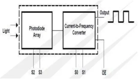
The TCS3200 programmable color light-to-frequency converter combines configurable silicon photodiodes and a current-to-frequency converter on single monolithic CMOS integrated circuit. The output is a square wave (50% duty cycle) with frequency directly proportional to light intensity (irradiance). The full-scale output frequency can be scaled by one of three preset values via two control input pins. Digital inputs and digital output allow direct interface to a microcontroller or other logic circuitry. Output enable (OE) places the output in the high-impedance state for multiple-unit sharing of a microcontroller input line. The light-to-frequency converter reads an 8 x 8 array of photodiodes. Sixteen photodiodes have blue filters, 16 photodiodes have green filters, 16 photodiodes have red filters, and 16 photo-diodes are clear with no filters.
Available Online at www.ijpret.com 91 The four types (colors) of photodiodes are interred digitized to minimize the effect of non-uniformity of incident ir-radiance. All 16 photodiodes of the same color are connected in parallel and which type of photodiode the device uses during operation is pin-selectable. Photodiodes are 120 mm x 120 mm in size and are on 144-mm centers. To TCS3200, when we use a color filter, it can allow only one particular color to get through and prevent other color. For example, when choose the red filter, only red incident light can get through, blue and green will be prevented. So we can get the red light intensity. Similarly, when choose other filters we can get blue or green light.
C. ZigBee Module
ZigBee is a low-cost, low-power, wireless mesh networking proprietary standard. The low cost allows the technology to be widely deployed in wireless control and monitoring applications, the low power-usage allows longer life with smaller batteries, and the mesh networking provides high reliability and larger range. ZigBee operates in the industrial, scientific and medical (ISM) radio bands; 868 MHz in Europe, 915 MHz in the USA and Australia, and 2.4 GHz in most jurisdictions worldwide. The technology is intended to be simpler and less expensive than other WPANs such as Bluetooth. Because ZigBee can activate (go from sleep to active mode) in 15msec or less, the latency can be very low and devices can be very responsive - particularly compared to Bluetooth wake-up delays, which are typically around three seconds.
Because ZigBees can sleep most of the time, average power consumption can be very low, resulting in long battery life. ZigBee protocols are intended for use in embedded applications requiring low data rates and low power consumption. ZigBee’s current focus is to define a general-purpose, inexpensive, self-organizing mesh network that can
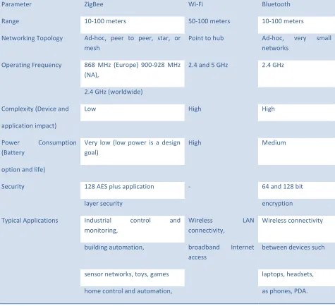
Available Online at www.ijpret.com 92 Be used for industrial control, embedded sensing, medical data collection, smoke and intruder warning, building automation, home automation, etc. The resulting network will use very small amounts of power - individual devices must have a battery life of at least two years to pass ZigBee certification. They are designed for high-throughput applications requiring low latency and predictable communication timing. Supported network Topologies: to-point, Point-to-multipoint & Peer-to-peer. Given below in Table I is the comparison of ZigBee, Wi-Fi and Bluetooth.
D. PIC18F4520 Microcontroller
Only 35 single word instructions to learn. All single-cycle instructions except for program branches, which are two-cycle. The PIC18F4520 features 32K bytes of program memory, 1536 bytes of SRAM and 256 bytes of EEPROM data memory, 36 I/O pins, 13 channels of 10-bit A/D, two analog comparators, two capture/compare/PWM modules, a synchronous serial port that can be configured as either 3-wire SPI or 2-wire I2C bus and an enhanced USART. The architecture is optimized for C compilers and the device features a 4x phase lock loop frequency multiplier allowing up to 10 MIPS performance. The part is supplied in a 40-pin DIP package, has an operating speed up to 40MHz (with 4x PLL), an operating temperature range of -40C to +85C, and is for 5V operation.
1) Features::
C compiler optimized architecture.
75 instructions (83 with extended instruction set en-abled).
4x phase lock loop (PLL) frequency multiplier allows clock speeds up to 40MHz.
Up to 10 MIPS performance. Internal oscillator block.
20 interrupt sources.
Priority levels for interrupts.
8 x 8 single-cycle hardware multiplier.
For reliable operation it uses programmable code pro-tection.
It also has power saving sleep mode.
Available Online at www.ijpret.com 93
TABLE I : COMPARISON OF WIRELESS MODULES
Parameter ZigBee Wi-Fi Bluetooth
Range 10-100 meters 50-100 meters 10-100 meters
Networking Topology Ad-hoc, peer to peer, star, or
mesh
Point to hub Ad-hoc, very small
networks
Operating Frequency 868 MHz (Europe) 900-928 MHz
(NA),
2.4 and 5 GHz 2.4 GHz
2.4 GHz (worldwide)
Complexity (Device and Low High High
application impact)
Power Consumption
(Battery
Very low (low power is a design goal)
High Medium
option and life)
Security 128 AES plus application - 64 and 128 bit
layer security encryption
Typical Applications Industrial control and
monitoring,
Wireless LAN
connectivity,
Wireless connectivity
building automation, broadband Internet
access
between devices such
sensor networks, toys, games laptops, headsets,
home control and automation, as phones, PDA.
E. APR9600 Voice Processor
Available Online at www.ijpret.com 94 recorders, toys, and many other consumer and industrial applications. Integrated achieves these high levels of storage capability by using its proprietary analog/multilevel storage technology implemented in an advanced Flash non-volatile memory process.
III. RESULTS (COLOR SENSOR)
TABLE II: COLOUR SENSOR OUTPUT
Serial No. Distance Detecting
(mm) (Yes or No)
1. 5 Yes
2. 10 Yes
3. 15 Yes
4. 20 Yes
5. 25 No
Shows the experimental setup of monitoring section respectively. In monitoring section, the sensing unit gathers the data and sends to the receiving station using the Zigbee node.
A. Features
Fig. 6. Block diagram of APR9600
Operating Voltage Range: 3V - 6.5V. Single Chip.
Available Online at www.ijpret.com 95
Fig. 7. Transmitter System
Fig. 8. Receiver System
High Quality Audio/Voice Recording & Playback So-lution 170/ 340/ 680 sec. Voice Recording Length in APR33A1/APR33A2/APR33A3.
Available Online at www.ijpret.com 96
IV. CONCLUSION
This paper is an approach to correspondence between music and colour adapted to people with disability using a multi-disciplinary approach. The choices of correspondence between colour and music have proven to work in a high percentage of people although the subjectivity of colour interpretation has pushed the researchers to maintain an open fan of possibilities for the users. It includes all the important ingredients in a proposal on a social and technological level with the objective to improve accessibility to information. The PIC18F4250 provides better performance when interface with TCS3200. Keeping the distance of object and sensor at a distance around 20 cm with a tolerence of 20 % gives better results.
REFERENCES
1. J. Rossi, F. Jose, P. Javier, Varona, Miquel Roca, “Transforming Colour into Melody and Implementing the Result in Colour Sensor Device,” Visualisation, 2009. VIZ ’09. Second International Conference in Barcelona, July 2009, pp 30 - 35.
2. K. Masica & L. Livermore,“ Recommended Practices Guide For Se-curing ZigBee Wireless Networks in Process Control System Environ-ments,” Control Systems Security Program (CSSP) April 2007 , April 2007.
3. Marko Paavola,“Wireless Technologies In Process Automation- Review And An Application,”
University of Oulu, Control Engineering Laboratory, Report A No 33, December 2007.
4. R. Morais, M. Fernandes, S. Matos, C. Serdio, P. Ferreira & M. Reis, “A ZigBee multi-powered wireless acquisition device for Remote sensing applications in precision viticulture,” Journal Computers and Electronics in Agriculture, Volume 62 Issue 2, July, 2008, pp 94-106.
5. K. George, Fourlas, K. Kalovrektis & E. Fountas, “Application of Robot Formation Scheme for Screening Solar Energy in a Green-house,” International Journal of Computer, Electrical, Automation, Con-trol and Information Engineering Vol: 3, No:9, 2009,pp 2247-2253.
6. Han-way huanng, “PIC Microcontroller - An introduction to soft-ware and hardware interfacing,” Delmar Cengage Learning, ISBN-13: 9781401839673, 2005.
7. Harpit Singh Sandhu, “Making of Pic Microcontroller Instrument and Controllers,” McGraw-Hill Professional, December 2008, ISBN: 0071606165.
8. Maxim-Dallas Semiconductor, “Why drive white LEDs with constant current,” APP 3256: Aug