Available Online At www.ijpret.com
INTERNATIONAL JOURNAL OF PURE AND
APPLIED RESEARCH IN ENGINEERING AND
TECHNOLOGY
A PATH FOR HORIZING YOUR INNOVATIVE WORKIMPROVING PRODUCTION IN AGRICULTURE USING SENSOR BASED TECHNIQUES
AND GREEN HOUSE CONCEPT
HARSHAD KUBADE, NISCHAL PURI, PRAFUL BAREKAR
1. Asst. Prof in Dept. of I.T, Priyadarshini Institute of Engineering & Technology, Nagpur. 2. Asst. Prof in Dept. of C.S.E, Priyadarshini Institute of Engineering & Technology, Nagpur.
Accepted Date:
27/02/2013
Publish Date:
01/04/2013
Keywords
Green House
Climate
Corresponding Author Mr. Harshad Kubade
Abstract
Available Online At www.ijpret.com Introduction
A greenhouse is a structure with a
glass or plastic roof and frequently glass or
plastic walls; it heats up because incoming
solar radiation from the sun warms plants,
soil, and other things inside the building. Air
warmed by the heat from hot interior
surfaces is retained in the building by the
roof and wall. These structures range in size
from small sheds to very large buildings.
Greenhouses can be divided into glass
greenhouses and plastic greenhouses.
Plastics mostly used are PEfilm and
multiwall sheet in PC or PMMA. Commercial
glass greenhouses are often high tech
production facilities for vegetables or
flowers. The glass greenhouses are filled
with equipment like screening installations,
heating, cooling, and lighting and may be
automatically controlled by a computer.
The glass used for a greenhouse works as a
selective transmission medium for different
spectral frequencies, and its effect is to trap
energy within the greenhouse, which heats
both the plants and the ground inside it.
This warms the air near the ground, and this
air is prevented from rising and flowing
away. This can be demonstrated by opening
a small window near the roof of a
greenhouse: the temperature drops
considerably. This principle is the basis of
the autovent automatic cooling system.
Greenhouses thus work by trapping
electromagnetic radiation and preventing
convection. A miniature
II. Real Time System for Agriculture
A real time system changes its state
as a function of physical time, e.g. a
chemical reaction continues to change its
state event after its controlling computer
system has stopped. It is reasonable to
decompose a real time system into a set of
subsystems called clusters.
1) Controlled Cluster -Controlled Object
2) Computational Cluster–Real time
computer or Microcontroller
Available Online At www.ijpret.com Figure 1 : A Real Time system Model for
Irrigation
The above system shows that the
controlled object are roofing mechanism,
watering mechanism and humidity
maintainer. The various sensors will read
the intensity of various parameters. The
intensity values read by sensors are in
analog (voltage) form, hence, it is necessary
to covert these values into digital format.
An analog-to-digital converter is used to
convert the analog values sent by sensors
into digital values. After the digitization
process, the digital values are given to the
computer. The computer will read the
values and check whether the particular
parameter value is exceeding its threshold
value. If so, then particular mechanism is
activated by computer to protect the plant
from adverse effect. For example, if
temperature increases to or above the set
threshold value then roofing action will be
taken. The roofing action may be
incremental or complete depending upon
the situation. As temperature decreases to
the threshold value, un-roofing will be
performed.
III. Sensors
A sensor is a device that measures a
physical quantity and converts it into a
signal which can be read by an observer or
by an instrument. For example, a mercury
thermometer converts the measured
temperature into expansion and
contraction of a liquid which can be read on
a calibrated glass tube. A thermocouple
converts temperature to an output voltage
which can be read by a voltmeter. For
accuracy, all sensors need to be calibrated
against known standards. Sensors are used
in everyday objects such as touch-sensitive
elevator buttons and lamps which dim or
brighten by touching the base. There are
also innumerable applications for sensors of
which most people are never aware.
Applications include cars, machines,
aerospace, medicine, manufacturing and
robotics. A sensor's sensitivity indicates
how much the sensor's output changes
when the measured quantity changes. For
instance, if the mercury in a thermometer
moves 1 cm when the temperature changes
by 1 °C, the sensitivity is 1 cm/°C. Sensors
Available Online At www.ijpret.com very high sensitivities. A good sensor obeys
the following rules:
1. the sensor should be sensitive to the
measured property
2. the sensor should be insensitive to
any other property
3. the sensor should not influence the
measured property
Ideal sensors are designed to be linear. The
output signal of such a sensor is linearly
proportional to the value of the measured
property. The sensitivity is then defined as
the ratio between output signal and
measured property. For example, if a sensor
measures temperature and has a voltage
output, the sensitivity is a constant with the
unit [V/K]; this sensor is linear because the
ratio is constant at all points of
measurement.
IV. Sensors for Agriculture
A. Sensor Resistance temperature detector
(RTD) Resistance Temperature
Detectors or RTDs for short, are wire wound
and thin film devices that measure
temperature because of the physical
principle of the positive temperature
coefficient of electrical resistance of metals.
The hotter they become, the larger or
higher the value of their electrical
resistance. They, in the case of Platinum
known variously as PRTs and PRT100s, are
the most popular RTD type, nearly linear
over a wide range of temperatures and
some small enough to have response times
of a fraction of a second. They are among
the most precise temperature sensors
available with resolution and measurement
uncertainties or ±0.1 °C or better possible in
special designs. Usually they are provided
encapsulated in probes for temperature
sensing and measurement with an external
indicator, controller or transmitter, or
enclosed inside other devices where they
measure temperature as a part of the
device's function, such as a temperature
Available Online At www.ijpret.com Figure 2: Resistance Temperature Device
The advantages of RTDs include stable
output for long period of time, ease of
recalibration and accurate readings over
relatively narrow temperature spans. Their
disadvantages, compared to the
thermocouples, are: smaller overall
temperature range, higher initial cost and
less rugged in high vibration environments.
They are active devices requiring an
B. Rainfall Sensors
A rain sensor or rain switch is a switching
device actuated by rainfall. There are two
main types of rain sensors. The first is a
water conservation device connected to an
automatic irrigation system that causes the
system to shut down in the event of rainfall.
The second is a device used to protect the
interior of an automobile from rain and to
support the automatic mode of wipers. A
rain sensor is an irrigation shut-off device
that prevents an automatic sprinkler system
from operating during and after a rainfall.
Rain sensors are available in several designs
and are usually connected into the
automatic irrigation system’s wiring. The
device overrides a scheduled irrigation after
a specific amount of rainfall has occurred.
When the collected rainwater has
evaporated from the device, scheduled
irrigations resume. Rain sensors are simple,
economical and useful tools for preventing
irrigation that would be wasteful. Rain
sensors for irrigation systems are available
in both wireless and hard-wired versions,
most employing hygroscopic disks that
swell in the presence of rain and shrink back
down again as they dry out - an electrical
switch is in turn depressed or released by
the hygroscopic disk stack has been sensed.
Some irrigation rain sensors also contain a
freeze sensor to keep the system from
operating in freezing temperatures
(typically freeze sensors are employed in
regions where irrigation systems are not
"blown-out" for the winter, yet there is
sometimes a chance of overnight frost).
C. Soil Moisture Sensor
Electromagnetic techniques include
methods that depend upon the effect of
moisture on the electrical properties of soil.
Soil resistively depends on moisture
content; hence it can serve as the basis for
a sensor. It is possible either to measure the
Available Online At www.ijpret.com measure the resistively of a material in
equilibrium with the soil. The difficulty with
resistive sensors is that the absolute value
of soil resistively depends on ion
concentration as well as on moisture
concentration. Therefore, careful
calibration is required for these techniques.
Measured Parameter: Soil water potential
aided by electrical resistance
measurements Response Time:
Instantaneous Disadvantages: Calibration
not stable with time and affected by ionic
concentration Cost of equipment to
generate signal and readout system is high
but could decrease with new solid-state
technology Advantages: Theoretically, can
provide absolute soil water content Can
determine water content at any depth
Sensor configuration can vary in size so
sphere of influence or measurement is
adjustable Relatively high level of precision
when ionic concentration of the soil does
not change Can be read by remote methods
V. Implementation of the System
Figure 3: Block Diagram for Irrigation
System
The above block diagram shows the soil
resistance to obtain a soil moisture level
reading. As the moisture level decreases the
resistance should increase. They could be
placed at different depths to give a better
overall indication of soil conditions.
Using a 3 pin temperature sensor unit
(possibly an NS ICLM35) to convert the
current temperature to an appropriate
voltage level. The three pins are ground, 5
volts and signal (1 – 4V). The signal would
be sent to an ADC (Analogue to
Digital Converter) which would send its
Available Online At www.ijpret.com Using a 3 pin humidity sensor component
(possibly a HIH3605A) to convert current
humidity to an appropriate voltage level.
The three pins are ground, 5 volts and signal
(1 – 4V). The signal would be sent to an ADC
(Analogue to
Digital Converter) which would send its
output to the microcontrollers input port.
Using a tipping bucket method of rainfall
level reading. This involves having a small
container on one side of a balance and a
counterweight on the other side. The
counterweight, in its starting position,
would interrupt light between the two parts
of an opt coupler (the emitter and the
receiver). When it rained, the container
would fill up, and at a certain point (most
likely to be calibrated to be when 1 mm of
rain had fallen) the container would reach
its lowest point and the counterweight
would reach its highest point, allowing light
to pass through the opt coupler. Just after
this, the container would tip over and
empty its contents. The output of the opt
coupler would be received by the computer
which would increment a rain counter on
every transition of signal state.
VI. Sprinkling System
.
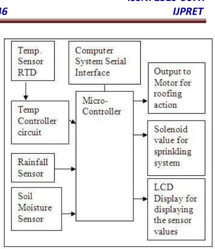
Figure 4: Block diagram of the Smart
Sprinkler System
The major components of the Smart
Sprinkler System are a computer, a
microcontroller, analog-to-digital
converters, sensors, and the circuitry to
open and close the solenoid sprinkler
Available Online At www.ijpret.com Hz household standard powers available to
run the Smart Sprinkler System. The
solenoid valves require 24 VAC/60 Hz to
properly open and close. We will
incorporate a step-down transformer to
convert the 120V to the required 24V
Relays requiring 5V to open will be used to
control the valves. Once the valves open,
the system becomes primarily mechanical.
The sprinkler heads will open due to the
water pressure in the pipes. At that stage,
sensing circuitry will determine how long to
irrigate to reach the desired moisture level
in the ground. Due to environmental
situations, the desired moisture level might
not always be reached. Hence, algorithms
will be in place to account for these
occurrences to ensure that irrigation is still
effective
VII. Automatic Agriculture System
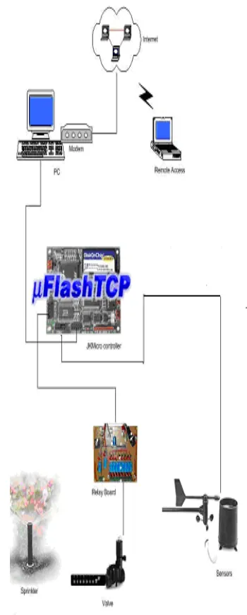
Figure 5 : Basic connectivity for Automatic
Irrigation System
Here sensor values are read by
microcontroller and processed by it. Relay
board is used for operating motors or valves
Available Online At www.ijpret.com sprinkling system. If rainfall is detected, the
sprinkling system is stopped. As the soil
moisture level decreases, the electrical
receptivity increases. At some point,
threshold value of receptivity, the valve of
sprinkling system is opened to operate the
sprinkling system.
VIII. Flow Diagram of the System
Figure 6 : Flow diagram of the
system
In above flow diagram, we have
used the polling method for reading the
values of sensors continuously. Instead of
continuously checking the status of sensors,
after the particular time intervals, values of
sensors can also be checked. We can also
use interrupt driven system. In interrupt
driven system, when the particular set
values are violated, then only signals are
given to the processing so that appropriate
action can be taken. The appropriate action
can be the roofing of the area when
temperature increases or rainfall is
detected, starting the watering system
automatically when the low humidity is
detected. For roofing purpose, the D.C.
motor with delay can be used or stepper
motor can be used for stepwise roofing.
IX. Conclusion
Several international studies, as well
as recent surveys in France, have shown
that the performance of irrigation practices
and equipment, especially in the uniformity
of water application, is still too low. This is
due to farmers lacking the management
skills to manage their irrigation systems
Available Online At www.ijpret.com in crop yields and a waste of water
resources. To improve irrigation
performance, it is necessary not only to
promote the implementation of irrigation
scheduling methods, but concurrently to
improve system design and make some
automotive techniques to increase the
production. Various advanced irrigation
methods have been developed in recent
years like irrigation controlling based on
computer or computer through sensors,
remote messaging. The advanced
controlling techniques automated roofing,
sprinkling system etc.
X. References
1. Real Time Systems – Design Principles
for Distributed Embedded Applications,
Hermann Kopetz, Kluwer International
Publications
2. Development and Test of Sensor-Aided
Microcontroller Based Irrigation System
with Web Browser Interface by Aaron Wills
and Curtin University
3. A practical guide to using soil moisture
sensors to control landscape irrigation by
Brent Q. Mecham, Northern Colorado
Water Conservancy District Loveland,
Colorado
4. Controlling of irrigation systems of
greenhouse plants by using measured
transpiration sum , U. Schmidt, E.Exarchou
5. Remote Sensing and Control of an
Irrigation System Using a Distributed
Wireless Sensor Network,Yunseop Kim;
Evans, R.G.; Iversen, W.M.
6. Sensor-Based Control of Irrigation in
BermudagrassBernard Cardenas-Lailhacar ,
Michael D. Dukes , Grady L. Miller
Environmental Horticulture Dept.,
University of Florida, Gainesville, FL
36211-0670,
7. The need to improve the on-farm
performance ofIrrigation systems to apply
upgraded irrigation scheduling, P. Augier,
D. Baudequin and C. Isbérie, Cemagref
(Division ouvrages ,hydrauliques et
équipementspourl'irrigation), Le Tholonet,
France
8. Choosing a Humidity Sensor: A Review
Available Online At www.ijpret.com 9. Design of a Sensor Based Smart
Sprinkler SystemThe International Journal
of Modern Engineering Volume 7, Number
1, fall 2006
10.Controlling method for rain runoff from
roof by green Roofing KunihiroOgihara Dr.
and Professor ofEngineering Department of
Civil and Environmental Engineering Toyo
University Kawagoe,Saitama, JAPAN
11.Softcomputing for greenhouse climate
controlCaponetto, R.; Fortuna, L.; Nunnari,
G.; Occhipinti, L.;Xibilia, M.G.Fuzzy Systems,
IEEE Transactions on Volume 8, Issue 6, Dec
2000 Page(s):753 – 760
12.Simulation of greenhouse energy
consumptionShimizu, H. Moriizumi, S.
Sch. of Agric., Ibaraki Univ., Japan;
13.Exploring the performance of an
evolutionary algorithmfor greenhouse
controlRasmus k. Ursem, BogdanFilipic,
Thiemokrink
14.New Development in Greenhouse
Technology can Mitigate the Water
Shortage problem of the 21st Century
Kooten, O. van; Heuvelink, E.; Stanghellini,
C. (2008) Acta Horticulturae 767. - p. 45 -
52.
15. http://www.fao.org/docrep/w4367e/w
4367e0e.html
16. http://www.ext.colostate.edu/pubs/Gar
den/07239.html
17. http://en.wikipedia.org/wiki/Greenhous
e
18.http://manatee.ifas.ufl.edu/lawn_and_gard
en/water_wisepdfs/RainSensorBrochure.pd