Design & Development of a Two-Phase Validation Commit Protocol
Approach to Guarantee Trustworthiness of Transactions on Cloud
Servers
M.Nandini
1; A. Sravanthi
2& Prof.Dr.G.Manoj Someswar
31
M.Tech.(CSE) from Narasimha Reddy Engineering College, Affiliated to JNTUH, Hyderabad, Telangana,
India
2
M.Tech. (CSE), Assistant Professor, Department of CSE, Narasimha Reddy Engineering College,
Affiliated to JNTUH, Hyderabad, Telangana, India
3
B.Tech., M.S.(USA), M.C.A., Ph.D., Principal & Professor, Department Of CSE, Anwar-ul-uloom
College of Engineering & Technology, Affiliated to JNTUH, Vikarabad, Telangana, India
ABSTRACT:
In distributed transactional database systems deployed over cloud servers, entities cooperate to form proofs of authorizations that are justified by collections of certified credentials. These proofs and credentials may be evaluated and collected over extended time periods under the risk of having the underlying authorization policies or the user credentials being in inconsistent states. It therefore becomes possible for policy-based authorization systems to make unsafe decisions that might threaten sensitive resources. In this research paper, we highlight the criticality of the problem. We then define the notion of trusted transactions when dealing with proofs of authorization. Accordingly, we propose several increasingly stringent levels of policy consistency constraints and present different enforcement approaches to guarantee the trustworthiness of transactions executing on cloud servers. We propose a Two-Phase Validation Commit protocol as a solution, which is a modified version of the basic Two-Phase Validation Commit protocols. We finally analyze the different approaches presented using both analytical evaluation of the overheads and simulations to guide the decision makers to which approach to use.
KEYWORDS: Infrastructure-as-a-Service (IaaS),; Platform-as-a-Service (PaaS); Software-as-a-Service (SaaS);
automated trust negotiation (ATN); National Institute of Standards and Terminology (NIST); Automated Trust Negotiation (ATN)
INTRODUCTION
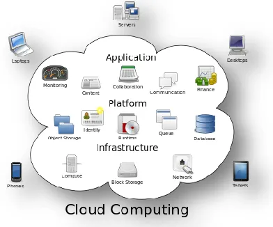
Cloud computing is the use of computing resources
(hardware and software) that are delivered as a service over a network (typically the Internet). The name comes from the common use of a cloud-shaped symbol as an abstraction for the complex infrastructure it contains in system diagrams. Cloud computing entrusts remote services with a user's data, software and computation. Cloud computing consists of hardware and software resources made available on the Internet as managed third-party services. These services typically provide access to advanced software applications and high-end networks of server
The goal of cloud computing is to apply traditional supercomputing, or high-performance computing power, normally used by military and research facilities, to perform tens of trillions of computations per second, in consumer-oriented applications such as financial portfolios, to deliver personalized information, to provide data storage or to power large, immersive computer games.[1]
The cloud computing uses networks of large groups of servers typically running low-cost consumer PC technology with specialized connections to spread
data-processing chores across them. This
shared IT infrastructure contains large pools of systems that are linked together. Often, virtualizationtechniques are used to maximize the power of cloud computing.
Characteristics and Services Models: The
salient characteristics of cloud computing based on the definitions provided by the National Institute of Standards and Terminology (NIST) are outlined below:
On-demand self-service: A consumer can
unilaterally provision computing capabilities, such as server time and network storage, as needed automatically without requiring human interaction with each service’s provider.
Broad network access: Capabilities are
available over the network and accessed through standard mechanisms that promote use by heterogeneous thin or thick client platforms (e.g., mobile phones, laptops, and PDAs).
Resource pooling: The provider’s computing
resources are pooled to serve multiple consumers using a multi-tenant model, with different physical and virtual resources dynamically assigned and reassigned according to consumer demand. There is a sense of location-independence in that the customer generally has no control or knowledge over the exact location of the provided resources but may be able to specify location at a higher level of abstraction (e.g., country, state, or data center). Examples of resources include storage,
processing, memory, network bandwidth, and virtual machines.
Rapid elasticity: Capabilities can be rapidly
and elastically provisioned, in some cases automatically, to quickly scale out and rapidly released to quickly scale in. To the consumer, the capabilities available for provisioning often appear to be unlimited and can be purchased in any quantity at any time.
Measured service: Cloud systems
automatically control and optimize resource use by leveraging a metering capability at some level of abstraction appropriate to the type of service (e.g., storage, processing, bandwidth, and active user accounts). Resource usage can be managed, controlled, and reported providing transparency for both the provider and consumer of the utilized service. [2]
Figure 2:Characteristics of cloud computing Services Models:
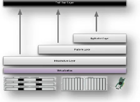
Figure 3: Structure of service models Benefits of cloud computing:
1. Achieve economies of scale – increase volume
output or productivity with fewer people. Your cost per unit, project or product plummets.
2. Reduce spending on technology
infrastructure. Maintain easy access to your
information with minimal upfront spending. Pay as you go (weekly, quarterly or yearly), based on demand.
3. Globalize your workforce on the cheap.
People worldwide can access the cloud, provided they have an Internet connection.
4. Streamline processes. Get more work done in
less time with less people.
5. Reduce capital costs. There’s no need to spend
big money on hardware, software or licensing fees.
6. Improve accessibility. You have access
anytime, anywhere, making your life so much easier!
7. Monitor projects more effectively. Stay
within budget and ahead of completion cycle times.
8. Less personnel training is needed.It takes
fewer people to do more work on a cloud, with a minimal learning curve on hardware and software issues.
9. Minimize licensing new software. Stretch and
grow without the need to buy expensive software licenses or programs.
10. Improve flexibility. You can change direction
without serious ―people‖ or ―financial‖ issues at stake. [4]
Advantages:
1. Price: Pay for only the resources used.
2. Security: Cloud instances are isolated in the
network from other instances for improved security.
3. Performance: Instances can be added instantly
for improved performance. Clients have access to the total resources of the Cloud’s core hardware.
4. Scalability: Auto-deploy cloud instances when
needed.
5. Uptime:Uses multiple servers for maximum
redundancies. In case of server failure, instances can be automatically created on another server.
6. Control: Able to login from any location.
Server snapshot and a software library lets you deploy custom instances.
7. Traffic: Deals with spike in traffic with quick
deployment of additional instances to handle the load.[5]
LITERATURE SURVEY
transactional data access. This paper aims at providing the design of a system in progress, highlighting the major design choices, analyzing the different guarantees provided by the system, and identifying several important challenges for the research community striving for computing in the cloud.[7] In trust negotiation and other distributed proving systems, networked entities cooperate to form proofs that are justi?ed by collections of certi?ed attributes. These attributes may be obtained through interactions with any number of external entities and are collected and validated over an extended period of time. Though these collections of credentials in some ways resemble partial system snapshots, these systems currently lack the notion of a consistent global state in which the satisfaction of authorization policies should be checked.[8] In this paper, we argue that unlike the notions of consistency studied in other areas of distributed computing, the level of consistency required during policy evaluation is predicated solely upon the security requirements of the policy evaluator. As such, there is little incentive for entities to participate in complicated consistency preservation schemes like those used in distributed computing, distributed databases, and distributed shared memory.[9] We go on to show that the most intuitive notion of consistency fails to provide basic safety guarantees under certain circumstances and then propose several more refined notions of consistency which provide stronger safety guarantees. We provide algorithms that allow each of these re ?need notions of consistency to be attained in practice with minimal overheads.
In automated trust negotiation (ATN), two parties exchange digitally signed credentials that contain attribute information to establish trust and make access control decisions. Because the information in question is often sensitive, credentials are protected according to access control policies. In traditional ATN, credentials are transmitted either in their entirety or not at all.[10] This approach can at times fail unnecessarily, either because a cyclic dependency makes neither negotiator willing to reveal her credential before her opponent,
because the opponent must be authorized for all attributes packaged together in a credential to receive any of them, or because it is necessary to fully disclose exact attribute values, rather than merely proving they satisfy some predicate (such as being over 21 years of age). Recently, several cryptographic credential schemes and associated protocols have been developed to address these and other problems. However, they can be used only as fragments of an ATN process. This paper introduces a framework for ATN in which the diverse credential schemes and protocols can be combined, integrated, and used as needed. A policy language is introduced that enables negotiators to specify authorization requirements that must be met by an opponent to receive various amounts of information about certified attributes and the credentials that contain it.[11] The language also supports the use of uncertified attributes, allowing them to be required as part of policy satisfaction, and to place their (automatic) disclosure under policy control.
introducing all-or-nothing sharing: a user, who allows a friend to use one of her credentials once, gives him the ability to use all of her credentials, i.e., taking over her identity. [13] This is implemented by a new primitive, called circular encryption, which is of independent interest, and can be realized from any semantically secure cryptosystem in the random oracle model. A transaction is traditionally defined so as to provide the properties of atomicity, consistency, integrity, and durability (ACID) for any operation it performs. In order to ensure the atomicity of distributed transactions, an atomic commit protocol needs to be followed by all sites participating in a transaction execution to agree on the final outcome, that is, commit or abort.[14] A variety of commit protocols have been proposed that either enhance the performance of the classical two-phase commit protocol during normal processing or reduce the cost of recovery processing after a failure. In this chapter, we survey a number of two-phase commit variants and optimizations, including some recent ones, providing an insight in the performance trade-off between normal and recovery processing. We also analyze the performance of a representative set of commit protocols both analytically as well as empirically using simulation.[15]
SYSTEM STUDY FEASIBILITY STUDY
The feasibility of the project is analyzed in this phase and business proposal is put forth with a very general plan for the project and some cost estimates. During system analysis the feasibility study of the proposed system is to be carried out. This is to ensure that the proposed system is not a burden to the company. For feasibility analysis, some understanding of the major requirements for the system is essential. Three key considerations involved in the feasibility analysis are
ECONOMICAL FEASIBILITY
TECHNICAL FEASIBILITY
SOCIAL FEASIBILITY
ECONOMICAL FEASIBILITY
This study is carried out to check the economic impact that the system will have on the organization. The amount of fund that the company can pour into the research and development of the system is limited. The expenditures must be justified. Thus the developed system as well within the budget and this was achieved because most of the technologies used are freely available. Only the customized products had to be purchased.
TECHNICAL FEASIBILITY
This study is carried out to check the technical feasibility, that is, the technical requirements of the system. Any system developed must not have a high demand on the available technical resources. This will lead to high demands on the available technical resources. This will lead to high demands being placed on the client. The developed system must have a modest requirement, as only minimal or null changes are required for implementing this system.
SOCIAL FEASIBILITY
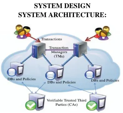
SYSTEM DESIGN SYSTEM ARCHITECTURE:
Figure 4: System Architecture DATA FLOW DIAGRAM:
1. The DFD is also called as bubble chart. It is a simple graphical formalism that can be used to represent a system in terms of input data to the system, various processing carried out on this data, and the output data is generated by this system.
2. The data flow diagram (DFD) is one of the most important modeling tools. It is used to
model the system components. These
components are the system process, the data used by the process, an external entity that interacts with the system and the information flows in the system.
3. DFD shows how the information moves through the system and how it is modified by a series of transformations. It is a graphical technique that depicts information flow and the transformations that are applied as data moves from input to output.
4. DFD is also known as bubble chart. A DFD may be used to represent a system at any level of abstraction. DFD may be partitioned into levels that represent increasing information flow and functional detail.
Registered with Policies
Login
Check
User Transaction Manager CA
Cloud Server
File Upload View the User Uploaded Files View the User
Uploaded Files
Check the User Policies
Verify the Policies
Verify the Server Response
Complete the Transaction Give the Access Credentials to Users
View the Files
Download the Files
Figure 5: Data Flow Diagram UML DIAGRAMS
UML stands for Unified Modeling Language. UML is a standardized general-purpose modeling language in the field of object-oriented software engineering. The standard is managed, and was created by, the Object Management Group.
The goal is for UML to become a common language for creating models of object oriented computer software. In its current form UML is comprised of two major components: a Meta-model and a notation. In the future, some form of method or process may also be added to; or associated with, UML. The Unified Modeling Language is a standard language for specifying, Visualization, Constructing and documenting the artifacts of software system, as well as for business modeling and other non-software systems.
The UML represents a collection of best engineering practices that have proven successful in the modeling of large and complex systems.
The UML is a very important part of developing objects oriented software and the software development process. The UML uses mostly graphical notations to express the design of software projects.
GOALS:
The Primary goals in the design of the UML are as follows:
1. Provide users a ready-to-use, expressive visual modeling Language so that they can develop and exchange meaningful models.
3. Be independent of particular programming languages and development process.
4. Provide a formal basis for understanding the modeling language.
5. Encourage the growth of OO tools market. 6. Support higher level development concepts
such as collaborations, frameworks, patterns and components.
7. Integrate best practices.
USE CASE DIAGRAM:
A use case diagram in the Unified Modeling Language (UML) is a type of behavioral diagram defined by and created from a Use-case analysis. Its purpose is to present a graphical overview of the functionality provided by a system in terms of actors, their goals (represented as use cases), and any dependencies between those use cases. The main purpose of a use case diagram is to show what system functions are performed for which actor. Roles of the actors in the system can be depicted.
User
CA
Transaction Manager
Verify the Policies
Check the Server Response
Complete the Transaction
View & Download the Files Register with
Policies
Cloud Server Give Access
Credentials to User
Upload the File
Check the User Policies
Figure 6: Use Case Diagram CLASS DIAGRAM:
In software engineering, a class diagram in the Unified Modeling Language (UML) is a type of static structure diagram that describes the structure of a system by showing the system's classes, their attributes, operations (or methods), and the relationships among the classes. It explains which class contains information.
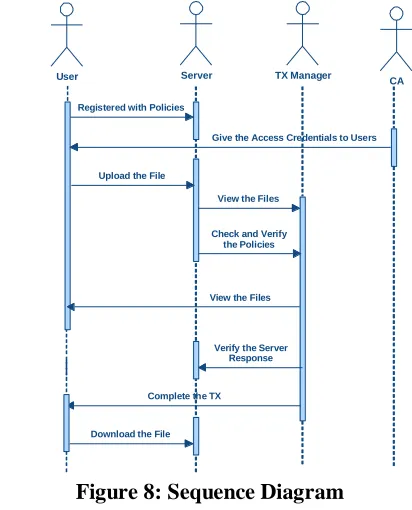
Figure 7: Class Diagram SEQUENCE DIAGRAM:
A sequence diagram in Unified Modeling Language (UML) is a kind of interaction diagram that shows how processes operate with one another and in what order. It is a construct of a Message Sequence Chart. Sequence diagrams are sometimes called event diagrams, event scenarios, and timing diagrams.
User Server TX Manager CA
Registered with Policies
Give the Access Credentials to Users
Upload the File
View the Files
Check and Verify the Policies
View the Files
Verify the Server Response
Complete the TX
Download the File
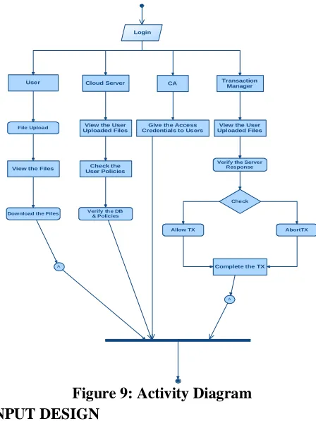
Figure 8: Sequence Diagram ACTIVITY DIAGRAM:
step-by-step workflows of components in a system. An activity diagram shows the overall flow of control.
A
A
Login
User Cloud Server CA Transaction Manager
File Upload
View the Files
Download the Files
View the User Uploaded Files
Check the User Policies
Verify the DB & Policies
Give the Access
Credentials to Users Uploaded FilesView the User
Verify the Server Response
Check
Allow TX AbortTX
Complete the TX
Figure 9: Activity Diagram INPUT DESIGN
The input design is the link between the information system and the user. It comprises the developing specification and procedures for data preparation and those steps are necessary to put transaction data in to a usable form for processing can be achieved by inspecting the computer to read data from a written or printed document or it can occur by having people keying the data directly into the system. The design of input focuses on controlling the amount of input required, controlling the errors, avoiding delay, avoiding extra steps and keeping the process simple. The input is designed in such a way so that it provides security and ease of use with retaining the privacy. Input Design considered the following things:
What data should be given as input?
How the data should be arranged or coded?
The dialog to guide the operating personnel in providing input.
Methods for preparing input validations and steps to follow when error occur.
OBJECTIVES
1.Input Design is the process of converting a user-oriented description of the input into a computer-based system. This design is important to avoid errors in the data input process and show the correct direction to the management for getting correct information from the computerized system.
2.It is achieved by creating user-friendly screens for the data entry to handle large volume of data. The goal of designing input is to make data entry easier and to be free from errors. The data entry screen is designed in such a way that all the data manipulates can be performed. It also provides record viewing facilities. 3.When the data is entered it will check for its validity. Data can be entered with the help of screens. Appropriate messages are provided as when needed so that the user will not be in maize of instant. Thus the objective of input design is to create an input layout that is easy to follow
OUTPUT DESIGN
A quality output is one, which meets the requirements of the end user and presents the information clearly. In any system results of processing are communicated to the users and to other system through outputs. In output design it is determined how the information is to be displaced for immediate need and also the hard copy output. It is the most important and direct source information to the user. Efficient and intelligent output design improves the system’s relationship to help user decision-making.
1. Designing computer output should proceed in an organized, well thought out manner; the right output must be developed while ensuring that each output element is designed so that people will find the system can use easily and effectively. When analysis design computer output, they should Identify the specific output that is needed to meet the requirements.
2.Select methods for presenting information.
3.Create document, report, or other formats that contain information produced by the system.
Convey information about past activities, current status or projections of the
Future.
Signal important events, opportunities, problems, or warnings.
Trigger an action.
Confirm an action.
SYSTEM ANALYSIS EXISTING SYSTEM:
To provide scalability and elasticity, cloud services oftenmake heavy use of replication to ensure consistent performance and availability. As a result, many cloud services rely on the notion of eventual consistency when propagating data throughout the system. This consistency model is a variant of weak consistency that allows data to be inconsistent among some replicas during the update process, but ensures that updates will eventually be propagated to all replicas.
DISADVANTAGES OF EXISTING SYSTEM: Consistency problems can arise as
transactional database systems are deployed in cloud environments and use policy-based authorization systems to protect sensitive resources.
The system may suffer from policy inconsistencies during policy updates.
It is possible for external factors to cause user credential inconsistencies over the lifetime of a transaction.
PROPOSED SYSTEM:
We formalize the concept of trusted
transactions.
We define several different levels of policy consistency constraints and corresponding enforcement approaches that guarantee the trustworthiness of transactions executing on cloud servers.
We propose a Two-Phase Validation Commit (2PVC) protocol that ensures that a transaction is safe by checking policy, credential, and data consistency during transaction execution.
We carry out an experimental evaluation of our proposed approaches.
ADVANTAGES OF PROPOSED SYSTEM:
Identifies transactions that are both trusted and conform to the ACID properties of distributed database systems.
Guarantee the trustworthiness of transactions executing on cloud servers.
A transaction is safe by checking policy, credential, and data consistency during transaction execution.
Most suitable in various situations.
SYSTEM TESTING
The purpose of testing is to discover errors. Testing is the process of trying to discover every conceivable fault or weakness in a work product. It provides a way to check the functionality of components, sub assemblies, assemblies and/or a finished product It is the process of exercising software with the intent of ensuring that the
Software system meets its requirements and user expectations and does not fail in an unacceptable manner. There are various types of test. Each test type addresses a specific testing requirement.
TYPES OF TESTS Unit testing
Integration testing
Integration tests are designed to test integrated software components to determine if they actually run as one program. Testing is event driven and is more concerned with the basic outcome of screens or fields. Integration tests demonstrate that although the components were individually satisfaction, as shown by successfully unit testing, the combination of components is correct and consistent. Integration testing is specifically aimed at exposing the problems that arise from the combination of components.
Functional test
Functional tests provide systematic demonstrations that functions tested are available as specified by the
business and technical requirements, system
documentation, and user manuals.
Functional testing is centered on the following items: Valid Input : identified classes of valid input must be accepted.
Invalid Input : identified classes of invalid input must be rejected.
Functions : identified functions must be exercised.
Output : identified classes of application outputs must be exercised.
Systems/Procedures: interfacing systems or procedures must be invoked.
Organization and preparation of functional tests is focused on requirements, key functions, or special test cases. In addition, systematic coverage pertaining to identify Business process flows; data fields, predefined processes, and successive processes must be considered for testing. Before functional testing is complete, additional tests are identified and the effective value of current tests is determined.
System Test
System testing ensures that the entire integrated software system meets requirements. It tests a configuration to ensure known and predictable results. An example of system testing is the configuration oriented system integration test. System testing is based
on process descriptions and flows, emphasizing pre-driven process links and integration points.
White Box Testing
White Box Testing is a testing in which in which the software tester has knowledge of the inner workings, structure and language of the software, or at least its purpose. It is purpose. It is used to test areas that cannot be reached from a black box level.
Black Box Testing
Black Box Testing is testing the software without any knowledge of the inner workings, structure or language of the module being tested. Black box tests, as most other kinds of tests, must be written from a definitive source document, such as specification or requirements document, such as specification or requirements document. It is a testing in which the software under test is treated, as a black box .you cannot ―see‖ into it. The test provides inputs and responds to outputs without considering how the software works.
Unit Testing:
Unit testing is usually conducted as part of a combined code and unit test phase of the software lifecycle, although it is not uncommon for coding and unit testing to be conducted as two distinct phases.
Test strategy and approach
Field testing will be performed manually and functional tests will be written in detail.
Test objectives
All field entries must work properly.
Pages must be activated from the identified link.
The entry screen, messages and responses must not be delayed.
Features to be tested
Verify that the entries are of the correct format
No duplicate entries should be allowed
All links should take the user to the correct page.
Integration Testing
components on a single platform to produce failures caused by interface defects.
The task of the integration test is to check that components or software applications, e.g. components in a software system or – one step up – software applications at the company level – interact without error.
Test Results: All the test cases mentioned above
passed successfully. No defects encountered.
Acceptance Testing
User Acceptance Testing is a critical phase of any project and requires significant participation by the end user. It also ensures that the system meets the functional requirements.
Test Results: All the test cases mentioned above
passed successfully. No defects encountered.
IMPLEMENTATION MODULES:
1. Server Module. 2. Cloud User Module. 3. Transaction Manager. 4. Certificate Authorities.
MODULES DESCRIPTION: Server Model
In this Module, We design a cloud infrastructure consisting of a set of servers, where each server is responsible for hosting a subset of all data items belonging to a specific application domain.
Cloud User Module
In this Module, Users interact with the system by submitting queries or update requests encapsulated in ACID transactions.
Since transactions are executed over time, the state information of the credentials and the policies enforced by different servers are subject to changes at any time instance, therefore it becomes important to introduce precise definitions for the different consistency levels that could be achieved within a transaction’s lifetime. These consistency models strengthen the trusted transaction definition by defining the environment in which
policy versions are consistent relative to the rest of the system. Before we do that, we define a transaction’s view in terms of the different proofs of authorization evaluated during the lifetime of a particular transaction.
Transaction Manager
A transaction is submitted to a Transaction Manager(TM) that coordinates its execution. Multiple TMs could be invoked as the system workload increases for load balancing, but each transaction is handled by only one TM.
A common characteristic of most of our proposed approaches to achieve trusted transactions is the need for policy consistency validation at the end of a transaction. That is, in order for a trusted transaction to commit, its TM has to enforce either view or global consistency among the servers participating in the transaction.
Certificate Authorities
We use the set of all credentials, which are issued by the Certificate Authorities (CAs) within the system. We assume that each CA offers an online method that allows any server to check the current status of credentials that it has issued.
In this module, we provide a Safe transaction. A safe transaction is a transaction that is both trusted (i.e., satisfies the correctness properties of proofs of authorization) and database correct (i.e., satisfies the data integrity constraints).
and policy identifier for each policy used.
RESULTS &CONCLUSION
Despite the popularity of cloud services and their wide adoption by enterprises and governments, cloud providers still lack services that guarantee both data and access control policy consistency across multiple data centers. In this paper, we identified several consistency problems that can arise during cloud-hosted transaction processing using weak consistency models, particularly if policy-based authorization systems are used to enforce access controls. To this end, we developed a variety of lightweight proof enforcement and
consistency models—i.e., Deferred, Punctual,
Incremental, and Continuous proofs, with view or global consistency—that can enforce increasingly strong protections with minimal runtime overheads. We used simulated workloads to experimentally evaluate implementations of our proposed consistency models relative to three core metrics: transaction processing performance, accuracy (i.e., global versus view consistency and recency of policies used), and precision (level of agreement among transaction participants). We found that high performance comes at a cost: Deferred and Punctual proofs had minimal overheads, but failed to detect certain types of consistency problems. On the other hand, high-accuracy models (i.e., Incremental and Continuous) required higher code complexity to implement correctly, and had only moderate performance when compared to the lower accuracy schemes. To better explore the differences between these approaches, we also carried out a tradeoff analysis of our schemes to illustrate how application-centric requirements influence the applicability of the eight protocol variants explored in this paper.
REFERENCES
[1] M. Armbrust et al., ―Above the Clouds: A Berkeley View of Cloud Computing,‖ technical report, Univ. of California, Feb. 2009.
[2] S. Das, D. Agrawal, and A.E. Abbadi, ―Elastras: An Elastic Transactional Data Store in the Cloud,‖ Proc.
Conf. Hot Topics in Cloud Computing (USENIX HotCloud ’09), 2009.
[3] D.J. Abadi, ―Data Management in the Cloud: Limitations and Opportunities,‖ IEEE Data Eng. Bull., vol. 32, no. 1, pp. 3-12, Mar. 2009.
[4] A.J. Lee and M. Winslett, ―Safety and Consistency in Policy-Based Authorization Systems,‖ Proc. 13th ACM Conf. Computer and Comm. Security (CCS ’06), 2006.
[5] M. Myers, R. Ankney, A. Malpani, S. Galperin, and C. Adams, ―X.509 Internet Public Key Infrastructure Online Certificate Status Protocol - Ocsp,‖ RFC 2560, http://tools.ietf.org/html/rfc5280, June 1999.
[6] E. Rissanen, ―Extensible Access Control Markup Language (Xacml) Version 3.0,‖ http://docs.oasis-open.org/xacml/3.0/ xacml-3.0-core-spec-os-en.html, Jan. 2013.
[7] D. Cooper et al., ―Internet x.509 Public Key Infrastructure Certificate and Certificate Revocation
List (CRL) Profile,‖ RFC 5280,
http://tools.ietf.org/html/rfc5280, May 2008.
[8] J. Li, N. Li, and W.H. Winsborough, ―Automated Trust Negotiation Using Cryptographic Credentials,‖ Proc. 12th ACM Conf. Computer and Comm. Security (CCS ’05), Nov. 2005.
[9] L. Bauer et al., ―Distributed Proving in Access-Control Systems,‖ Proc. IEEE Symp. Security and Privacy, May 2005.
[11] J. Camenisch and A. Lysyanskaya, ―An Efficient System for Non-Transferable Anonymous Credentials with Optional Anonymity Revocation,‖ Proc. Int’l Conf. Theory and Application of Cryptographic Techniques: Advances in Cryptology (EUROCRYPT ’01), 2001.
[12] P.K. Chrysanthis, G. Samaras, and Y.J. Al-Houmaily, ―Recovery and Performance of Atomic Commit Processing in Distributed Database Systems,‖ Recovery Mechanisms in Database Systems, Prentice Hall PTR, 1998.
[13] M.K. Iskander, D.W. Wilkinson, A.J. Lee, and P.K. Chrysanthis, ―Enforcing Policy and Data Consistency of Cloud Transactions,‖ Proc. IEEE Second Int’l Workshop Security and Privacy in Cloud Computing (ICDCS-SPCCICDCS-SPCC), 2011.
[14] G. DeCandia et al., ―Dynamo: Amazons Highly Available Key-Value Store,‖ Proc. 21st ACM SIGOPS Symp. Operating Systems Principles (SOSP ’07), 2007. [15] F. Chang et al., ―Bigtable: A Distributed Storage System for Structured Data,‖ Proc. Seventh USENIX Symp. Operating System Design and Implementation