Volume 3, Special Issue 1, ICSTSD 2016
196
Secure data transfer using visible light
communication Technique
Sumit Jaykant Meshram
*1, Prof. Avinash P. Wadhe
2*1 Student of Master of Engineering (Computer Science & Engineering), Raisoni College of Engineering and Management, Amravati, India,
2 Head of Department, Computer Science & Engineering, Raisoni College of Engineering and Management, Amravati, India,
Abstract— Now a days many people are using internet
through the wireless device such as Wi-Fi hotspot, modem, etc. or some people are used wired network connection to accomplish their task. As number of users get increased in wireless network that’s why speed decreases proportionally. Though Wi-Fi gives us speed up to 150mbps as per IEEE 802.11n, it is still insufficient to accommodate number of desired users. To remedy some such a type of limitation and security problems of Wi-Fi by the unauthorized person we introducing the new concept called as Li-Fi (Light Fidelity) technology. In this paper we show the actual result of Li-Fi technology. We are created a module which is transferring the data through light and communicating the one computer to another computer and also show some result based on Li-Fi technology. This technology transfer data rate is up to 10 gigabits per second, which is faster than your average broadband connection, and also providing the strong security from unauthorized person.
Keywords—Li-Fi (Light Fidelity), LED (Light Emitting
Diode), VLC (Visible Light Communication),
I. INTRODUCTION
The incandescent bulb that has been widely used to lit our surroundings since its invention over a century ago but now we are using this LED everywhere, why? Because they consumed low power and low cost and very efficient to use. The LED have a great feature which is he glow up when (1) is pass to LEDs and gone off when pass digit (0). Now when we see the LEDs is glowing up that time it switching on and of very quickly, which is not recognize human eyes. This feature gives us nice opportunities for transmitting data. LED send data rate up to 10 Gbps. But the previous wireless network will provide high data rates is nearly 100 Mbps in IEEE 802.15.7 standard but still it is not sufficient for end of the user. Nowadays everywhere using the LEDs that’s why the rapid increase in the usage of LEDs has provided a
unique opportunity. Visible light communication (VLC) is a data communications medium using visible light between 400 THz (780 nm) and 800 THz (375 nm). Visible light is not injurious to vision. In the first system we are using the white LEDs because it is the combination of all seven colors, menaces we got all seven channel. But after that we have to do control all the light colors. That whys here we used the blue color LED. Menace we used only one channel over here. The switching rate is fast enough to be imperceptible by a human eye. This functionality can be used for communication where the data is encoded in the emitting light in various ways. A photo detector or the matrix of photodiodes can received the modulation request signal and decode the data.
Due to its high frequency, visible light cannot penetrate through most objects and walls.
Fig. 1: Working of Li-Fi reproduced from [7].
In this Visible light communication system you see how to securely data is transmitted source to destination using visible light communication.
II.
LITERATURE SURVAYVolume 3, Special Issue 1, ICSTSD 2016
197
On the just basis of transmission of data this, technology can be used to replace the existing RF based Wi-Fi system to connect to the internet.[11] In this paper the author say VLC provides the potential for multi-gigabit-per-second data rate communication at short distances with ~300 THz of available visible light spectrum at low power and cost, using simple LEDs and PDs. With the growing integration of LEDs in indoor and outdoor light sources, and advances in the design of low cost LEDs with fast sub nanosecond switching response times, the integration of lighting and communication provides significant potential for this technology. The two main challenges in communication in this spectrum are flicker mitigation and support for dimming. This article presents mechanisms to mitigate flicker and support dimming as defined in the IEEE 802.15.7 visible light communication standard.
[9] In this paper author say Visible light communication is a creative approach to combine illumination, wireless communication, and novel play patterns for connected toys. Since it can be implemented at low cost with components that are available in many toys, VLC facilitates toy networking and, in addition, communication with phones via cameras and flashlights. This is possible without the need for extra hardware. In the future, free space optics (infrared or VLC) can play an interesting role complementing traditional radio communication in consumer electronics.
III. IMPLIMENTATION OF LI-FI
The actual theme of our Li-Fi communication system is shown in below figure.
Fig. 2: Basic working system reproduced from [82].
Component Description:
1. IR Sensors:
An IR LED, also known as IR transmitter, is a special purpose LED that transmits infrared rays in the range of 760 nm wavelength. Such LEDs are usually made of gallium arsenide or aluminum gallium arsenide. They, along with IR receivers, are commonly used as sensors.
The appearance is same as a common LED. Since the human eye cannot see the infrared radiations, it is not possible for a person to identify whether the IR LED is working or not, unlike a common LED. To overcome this problem, the camera on a cell phone can be used. The camera can show us the IR rays being emanated from the IR LED in a circuit.
We are using here the infrared light as communication medium because of its low cost and better reception in short range communication. To make the receiver perform better it is designed to recognize the switching IR light of particular wavelength.
The wavelength and switching frequency can be taken from the manufacturers’ data sheets. This IR sensor is connected to the output of serial port. As we know that 8 bit data transfer from the serial port of the microcontroller. Thus, that particular code is transmitted in the form of light infrared waves.
2. Buffer Amplifier:
The output of sensor does not have the current capacity to drive the microcontroller hence we use the buffer amplifier between sensor and micro controller. It is a just a combination of transistor to amplify the low current weak signal.
3. Capacitors:
In a way, a capacitor is a little like a battery. Although they work in completely different ways, capacitors and batteries both store electrical energy. If you have read How Batteries Work.
You know that a battery has two terminals. Inside the battery, chemical reactions produce electrons on one terminal and absorb electrons at the other terminal. Like a battery, a capacitor has two terminals. Inside the capacitor, the terminals connect to two metal plates separated by a dielectric. The dielectric can be air, paper, plastic or anything else that does not conduct electricity and keeps the plates from touching each other. You can easily make a capacitor from two pieces of aluminum foil and a piece of paper. It won't be a particularly good capacitor in terms of its storage capacity, but it will work. In an electronic circuit, a capacitor is shown like this:
Volume 3, Special Issue 1, ICSTSD 2016
198
When you connect a capacitor to a battery, here’s what happens:•The plate on the capacitor that attaches to the negative terminal of the battery accepts electrons that the battery is producing.
•The plate on the capacitor that attaches to the positive terminal of the battery loses electrons to the battery.
Fig. 4: Capacitor and battery connector
TESTING:
To test the capacitors, either analog meters or special digital meters with the specified function are used. The non-electrolyte capacitor can be tested by using the digital meter.
Multi – meter mode: Continuity Positive probe: One end Negative probe: Second end Display: `0` (beep sound occur) `OL` Result: Faulty OK
4. LED:
LED falls within the family of P-N junction devices. The light emitting diode (LED) is a diode that will give off visible light when it is energized. In any forward biased P-N junction there is, with in the structure and primarily close to the junction, a recombination of hole and electrons. This recombination requires that the energy possessed by the unbound free electron be transferred to another state. The process of giving off light by applying an electrical source is called electroluminescence.
Fig. 5: LED and LED symbol
LED is a component used for indication. All the functions being carried out are displayed by led.The LED is diode which glows when the current is being flown through it in forward bias condition. The LEDs are available in the round shell and also in the flat shells. The positive leg is longer than negative leg.
Features:
- It provides clock pulses of 11.0952 MHz frequency. - The popularity of the crystals is due to low cost.
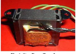
5. TRANSFORMER:
Transformer is a device that transfers electrical energy from one circuit to another through inductively coupled conductors — the transformer's coils or "windings". Except for air-core transformers, the conductors are commonly wound around a single iron-rich core, or around separate but magnetically-coupled cores. A varying current in the first or "primary" winding creates a varying magnetic field in the core (or cores) of the transformer. This varying magnetic field induces a varying electromotive force (EMF) or "voltage" in the "secondary" winding. This effect is called mutual induction.
Fig. 6: Step Down Transformer
If a load is connected to the secondary circuit, electric charge will flow in the secondary winding of the transformer and transfer energy from the primary circuit to the load connected in the secondary circuit.
The secondary induced voltage VS, of an ideal transformer, is scaled from the primary VP by a factor equal to the ratio of the number of turns of wire in their respective windings:
By appropriate selection of the numbers of turns, a transformer thus allows an alternating voltage to be stepped up — by making NS more than NP — or
stepped down, by making it
Volume 3, Special Issue 1, ICSTSD 2016
199
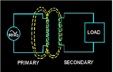
Refer to the transformer circuit in figure as you read the following explanation: The primary winding is connected to a 60-hertz ac voltage source. The magnetic field (flux) builds up (expands) and collapses (contracts) about the primary winding. The expanding and contracting magnetic field around the primary winding cuts the secondary winding and induces an alternating voltage into the winding. This voltage causes alternating current to flow through the load. The voltage may be stepped up or down depending on the design of the primary and secondary windings.Fig. 7: Primary and Secondary winding
6. Micro controller:
This is the part of card that stores the data in its EEPROM and performs all the operations required for testing the incoming data and to decide the response of received data. It also controls the mode of serial communication and speed of communication. Controller detects the status of pressed key and accordingly sends the digital code via serial port.
7. The serial port:
In computing, a serial port is a serial communication physical interface through which information transfers in or out one bit at a time (contrast parallel port). Throughout most of the history of personal computers, data transfer through serial ports connected the computer to devices such as terminals and various peripherals.
While such interfaces as Ethernet, FireWire, and USB all send data as a serial stream, the term "serial port" usually identifies hardware more or less compliant to the RS-232standard, intended to interface with a modem or with a similar communication device. Modern computers without serial ports may require serial-to-USB converters to allow compatibility with RS 232 serial devices. Serial ports are still used in applications such as industrial automation systems, scientific instruments, shop till systems and some industrial and consumer
products. Server computers may use a serial port as a control console for diagnostics. Network equipment (such as routers and switches) often use serial console for configuration. Serial ports are still used in these areas as they are simple, cheap and their console functions are highly standardized and widespread. A serial port requires very little supporting software from the host system.
8. IR Receiver
In our project, we have employed photodiode as an IR receiver. A photodiode is a type of photo detector capable of converting light into either current or voltage, depending upon the mode of operation. The common, traditional solar cell used to generate electric solar power is a large area photodiode.
9. LCD Display
LCD (Liquid Crystal Display) screen is an electronic display module and find a wide range of applications. A 16x2 LCD display is very basic module and is very commonly used in various devices and circuits. These modules are preferred over seven segments and other multi segment LEDs. The reasons being: LCDs are economical; easily programmable; have no limitation of displaying special & even custom characters (unlike in seven segments), animations and so on.
A 16x2 LCD means it can display 16 characters per line and there are 2 such lines. In this LCD, each character is displayed in 5x7-pixel matrix. This LCD has two registers, namely, Command and Data.
The command register stores the command instructions given to the LCD. A command is an instruction given to LCD to do a predefined task like initializing it, clearing its screen, setting the cursor position, controlling display etc. The data register stores the data to be displayed on the LCD. The data is the ASCII value of the character to be displayed on the LCD.
Working system block diagram:
Volume 3, Special Issue 1, ICSTSD 2016
200
The transmitter card unit has internal memory to store the digital codes. The data can be entered through VB application and can be seen in transmitter window of VB app, this data is than transfer to microcontroller via serial port for further processing. The data is displayed in the LCD. The controller sends it to buffer amplifier through serial port and send it to receiver part through IR transmitter.Fig. 9: Block Diagram of Receiver Unit
The receiver part receives the data from photo receiver and sends it to microcontroller and VB application through serial port. Controller stores it in the memory and also it displays the data in the LCD display and in receiver window of VB app. This is how the digital data can be transmitted.
IV. RESULT ANALYSIS
In this system communicating the one computer to another computer using VLC system. In that system to transfer the data vie the LED and received data from the photo sensor which is spectrum is 760 nm received. In this system used the blue LED which means only one channel to transferring the data. Below figure show the spectrum and wavelength of visiblelight.
Fig. 10: Luminosity function representing human eye’s sensitivity to different wavelengths in the visible spectrum; reproduced from [2].
Fig. 11: Different indoor surfaces exhibit different levels of spectral reflectance depending on the wavelength;
reproduced from [2].
The above graph show result of the Different indoor surfaces exhibit different levels of spectral reflectance depending on the wavelength which is represent the spectral reflection on the plastic wall, ceiling, floor, plaster wall.
Fig. 12: Relative position of transmitter and receiver; reproduced from [2].
In the above figure show the relative position of transmitter and receiver. In any angle you live the LED and it is catch the photo sensor if it is in range.
Fig. 13: normal light wavelength; reproduced from [16].
This is the normal light wavelength passing signal show in above figure. Which is actually the up side is considering 1 which menace light is on and below half cycle is consider as 0 which is off the light
Fig. 14: light wavelength with data transfer; reproduced from [16].
Volume 3, Special Issue 1, ICSTSD 2016
201
Fig. 15: Data transfer level; reproduced from [10].The above diagram shows the analysis of the different level of the transmission of medium range. And show the speed of data transfer using of this mode.
V. CONCLUSIONS
The LED-to-LED communication provides a unique opportunity to provide communication capabilities that is not noticed. From the simulation we can see that it is possible to transmit higher quality of data using visible light as a medium.
In this system we are transferring data vie one computer to another in a room using VLC system. The range of that transmitter spectrum to receiver is 2.5µm (760nm).
On the basis of transmission of data in high speed, not penetrating outside of wall, low cost of LED, no need to take permeation for used, etc. this lot of features of this technology can be used to replace the existing RF based Wi-Fi system to connect to the internet.
VI. FUETURE WORK
Here we developed the pear to pear communication system which is actually bidirectional system using VLC. This system you can used into the school, college, lab, hospital, aircraft, air plane, to commanding the robot, mobile to mobile communication, etc. where the RF is ban on some areas and RF is stickily unused on that range like petrol pump which is RF is cause the explosion on this areas.
REFERANCE
[1] S. Meshram, A. Wadhe, “Analysis for secure data transfer using visible light communication Technique,” IJERT, Aplril 2016.
[2] P. Pathak, X. Feng, P. Hu, P. Mohapatra, “Visible Light Communication, Networking and Sensing: A Survey, Potential and Challenges,” IEEE Communications Surveys & Tutorials 2015.
[3] B. Li, J. Wang, Senior Member, IEEE R. Zhang, Member, IEEE H. Shen Chunming Zhao, Member, IEEE L. Hanzo, Fellow, IEEE, “Multiuser MISO Transceiver Design for Indoor Downlink Visible Light Communication Under Per-LED Optical Power Constraints,” IEEE Photonics Journal Vol. 7, No. 4, August 2015.
[4] Y. Li, M. Safari, R. Henderson, H. Haas, “Optical OFDM With Single-Photon,” IEEE PHOTONICS TECHNOLOGY LETTERS, VOL. 27, NO. 9, MAY 1, 2015.
[5] W. Yuanquan, C. Nan, “A High-Speed Bi-Directional Visible Light Communication System Based on RGB-LED,” China Communications, 2014
[6] S. Hossain, S. Islam, Z. Abadin, A. Hosssin, “Methodology to Achieve Enhanced Data Transmition Rate using Li-Fi in VLC Technology,” IJER, 2014. [7] P. Polshetwar, S. Siddiqui, “Li-Fi Technology,” IJCSIT,
2014.
[8] A. Kurup, V. Tiwari, Selvanathiya, “Implementation and Demonstration of Li-Fi Technology," IJRET, March 2014.
[9] G. Corbellini, K. Aks ¸ S. Schmid, S. Mangold, and T. R. Gross, Disney Research “Connecting Networks of Toys and Smartphones with Visible Light Communication,”IEEE Communications Magazine, July 2014.
[10] D. Nivrutti, R. Nimvalkar, “Light-Fidelity: A Reconnaissance of Future Technology,” IJARCSSE, 2013.
[11] S. Rajagopal, S. Electronics, Rd D. Roberts, Intel Sang-Kyu Lim, ETRI, “IEEE 802.15.7 Visible Light Communication: Modulation Schemes and Dimming Support,” IEEE Communications Magazine, March 2012.
[12] S. Schmid, G. Corbellini, S. Mangold, T. R. Gross, Disney Research “An LED-to-LED Visible Light Communication System with Software-Based Synchronization,” 3rd IEEE Workshop on Optical Wireless Communications (OWC'12), 2012.
[13] S. Schmid, D. Schwyny, K. Aks, G. Corbellini, T. R. Grossy, S. Mangold “From Sound to Sight: Using Audio Processing to enable Visible Light Communication,” Disney Research Zurich.
[14] S. Schmid, G. Corbellini, S. Mangold, T. R. Gross, “Continuous Synchronization for LED-to-LED Visible Light Communication Networks,” Disney Research Zurich.
[15] S. Schmid, G. Corbellini, S. Mangold, T. R. Gross “LED-to-LED Visible Light Communication Networks,” Disney Research Zurich.
![Fig. 1: Working of Li-Fi reproduced from [7].](https://thumb-us.123doks.com/thumbv2/123dok_us/8875317.1816511/1.595.307.535.473.582/fig-working-li-fi-reproduced.webp)
![Fig. 2: Basic working system reproduced from [82].](https://thumb-us.123doks.com/thumbv2/123dok_us/8875317.1816511/2.595.338.478.679.749/fig-basic-working-reproduced.webp)
![Fig. 14: light wavelength with data transfer; reproduced from [16].](https://thumb-us.123doks.com/thumbv2/123dok_us/8875317.1816511/5.595.91.290.192.348/fig-light-wavelength-data-transfer-reproduced.webp)
![Fig. 15: Data transfer level; reproduced from [10].](https://thumb-us.123doks.com/thumbv2/123dok_us/8875317.1816511/6.595.76.292.73.209/fig-data-transfer-level-reproduced-from.webp)
