448
Macros in Catia to Read Values from MS Excel
- A Tool for Automation
Rajesh Pansare
1Assistant Professor1
Department of Mechanical Engineering K. J. Somaiya College of Engineering,
Mumbai - 400077, India. [email protected]
Manoj Palsodkar
2Workshop Supdt.2
Department of Mechanical Engineering K. J. Somaiya College of Engineering,
Mumbai-400077, India. [email protected]
Abstract— The fundamental objective of this paper is to discuss a method of task automation of solid modelling. This task automation is achieved using macros in CATIA V5 working under windows operating system using visual basic programming language. The macros in this program code are written/recorded in visual basic programming language. This paper demostrates the process of reading the values from MS Excel file using macros to generate solid model in CATIA V5. The values from an excel file are taken as parameters of the solid model. The paper is divided into three parts, the first part explains the need of automation, basic nature and requirements of macros. The second part includes the actual code used to read values from MS Excel for design automation of Centrifugal pump. The third part includes how these macros can be used for various other applications. The findings from our work will be to show that after calculating parameters for Centrifugal Pump in MS Excel, we can read these values in CATIA V5 using macros so as to get the solid model of the same in CATIA. Using such technique, the repetative tasks of design of any component can be reduced so as to improve the quality of design as well as to reduce the cost of same thereby improving effectiveness and efficiency of design process.
Keywords— Macros, Solid Modelling, Design Automation.
I. INTRODUCTION
The competitiveness of any industry depends on information and knowledge in product design and manufacturing processes. This is now becoming important factor for new product design and development. This is the reason why industries are now shifting from traditional design methods to modern knowledge based design processes.
Design automation provides industrial firms with a complete arsenal to attack waste, both in how the product is produced (process improvement using lean manufacturing techniques) and in what way product gets produced (product improvement using lean design).To be cost competitive, front-line staff must learn to see waste and relentlessly pursue its elimination not only on the manufacturing floor but also on their engineering drafting boards and computer screens.
Design automation is a means of defining and using procedural programs that encapsulate trade-oriented knowledge to reduce the amount of interactions required from a user to achieve a modelling task. For instance, automation is generally achieved using Computer-Aided Design (CAD) system. Day by day the competition is increasing in the market. Hence the cost of the component is playing important role to withstand in the market. Profit
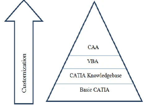
margins are reducing. To reduce the cost of component the processing time has to be reduced specially cost of engineering activities. Figure 1 shows how the design process can be customised using various tools.
Figure 1. Customised Design Process
449
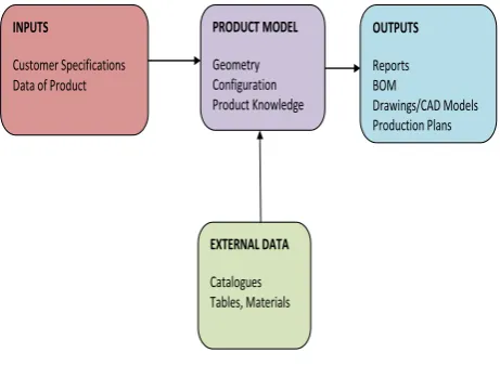
INPUTS
Customer Specifications Data of Product
PRODUCT MODEL
Geometry Configuration Product Knowledge
OUTPUTS
Reports BOM
Drawings/CAD Models Production Plans
EXTERNAL DATA
Catalogues Tables, Materials
Figure 2. The KBE System
Benefits with KBE are that optimization of product concepts is easier and product and process knowledge is stored. Drawbacks are that it is time demanding to develop KBE systems and it can sometimes be seen as a “black box” if the automated procedures are poorly explained to the user.
II. METHODOLOGY
CATIA (Computer Aided Three dimensional Interactive Application) provides the users with the wide range of tools that can be used for automation of some phases of the design process or for building up and sharing knowledge. The modeling command sequence or modeling history can be recorded. This set of commands is called as macro. If one could devise a systematic method of capturing the information, then it would be possible to develop a process to automate the creation of user documentation, parameter-validation code, testing documents, and even a customized template for the macro. Besides saving time and effort, major benefits of such process would be the standardization and improved quality that would naturally result.
The high-level dynamic interface including history of user commands is also recorded in macro file. CATIA V5 Knowledge ware tools allow the user to capture and use the intelligence contained within the part. CATIA V5 macro and scripting capabilities allow the user to be prompted for the critical dimensions. CATIA V5 then takes the information and updates the part according to the supplied input. CATIA V5 also automatically updates the standard dimensioned drawing (CAT Drawing). The dimensioned drawing is ready to be released to the production floor in few minutes. Such macros are very useful in practice and saves time of designer. These macros could be a useful and very easy instrument for the new projects in the aerospace and automotive domain, if one inputs some modeling parts rules, similar with AIRBUS part experience. The design time is also reduced using macros.
Considering the above said advantages of macros the authors have tried for design automation of centrifugal pump. The standard procedure for design of centrifugal pump is used for this research work. For designing Centrifugal pump parameters like Suction Head (Hs), Length of Suction Pipe (Ls), Delivery Head (Hd), Length of Delivery Pipe (Ld), Flow Rate (Q) are required. Once these parameters are decided same are fed to MS Excel. By using the features available in MS Excel calculations are done for various dimensions. The excel worksheet shows step by step design of each component, summary report of all dimensions. These dimensions are stored in MS Excel. These values are extracted by using CATIA macro as explained later.
Figure 3. Flowchart of System
All these dimensions help to generate 3 dimensional drawings in CATIA using macros. Also one can extract 2 dimensional views. This eliminates the repetitive efforts which designer has to do for design of centrifugal pump. Even if there is change in any of the above listed parameter, the designers need not redraw all the components of centrifugal pump.
III. CATIA V5 FOR AUTOMATION
CATIA is a multi-platform PLM/CAD/CAM/CAE commercial software suite developed by Dassault Systems and marketed worldwide by IBM. Commonly referred to as 3D Product Lifecycle Management software suite, CATIA supports multiple stages of product development (CAX). The stages range from conceptualization, through design (CAD), analysis (CAE), until manufacturing (CAM). CATIA provides open development architecture through the use of interfaces, which can be used to customize or develop applications.
450 applied in a wide variety of industries, such as aerospace, automotive, industrial machinery, electrical, electronics, shipbuilding, plant design, consumer goods, including design for products like jewelry and clothing.
IV.OBJECT LINKING AND EMBEDDING (OLE) AUTOMATION
The Object Linking and Embedding (OLE) Automation is used to interact CATIA with MS Excel. The CATIA has a library and Application Programming Interface (API) documentation. This enables Visual Basic for Applications (VBA) programs to interact with the application. These VBA programs are developed for the OLE Automation interface of some particular application. But they cannot be used for automation of some other application, even if that application hosts the Visual Basic runtime. The reason for this is the OLE Automation interfaces will be different for different application. For example, if a VBA program is developed for automation of Microsoft Word cannot be used with another word processor though the word processor hosts VBA.
At the same time the multiple applications can be automated with help of one host. This is done by creating application objects within the VBA code. Also the reference to the different libraries has to be created within the VBA client. These application objects create the OLE link to the application when they are first created.
V. MACROS
If input parameters are changed, the design steps need to be repeated. One can not avoid these repeating sequences in traditional way of product design. These repeated tasks requires lot of time, efforts and involves some cost. Using macros i.e. small programs in the programming language CATScript (VB-Script) or CATVBA (Visual Basic for Applications) can be automated via CATIA V5 interface. Processes or supporting data with other applications, VBA, Excel, Power Point can be used as parameters for this. These macros may be useful for creating, analyzing, measuring, modifying, translating, optimizing surfaces, solids, wireframes and more. Macros are also useful for assembly operations, CAM operations and all multidisciplinary applications. It is also possible to design targeted tuning of parametric geometry and the use of macros automatically vary within seconds. Also many CATIA standard features extended through macros become more user friendly and effective. A good example of automation is one can extract the values from Ms Excel and these values can be used for parametric design process. With the said work author has tried to extract various design parameters of Centrifugal pump from Ms Excel and use it in CATScript for automation of geometry generation in CATIA. The time required for the documentation of design process is saved by using such systems. The data records must meet the customers requirements before delivery.
Macro allows us to automate various repetitive tasks. Macros can be used for various software’s such as Windows, AutoCAD, and CATIA etc. A macro is a way to store instructions intended to be repeated many times.
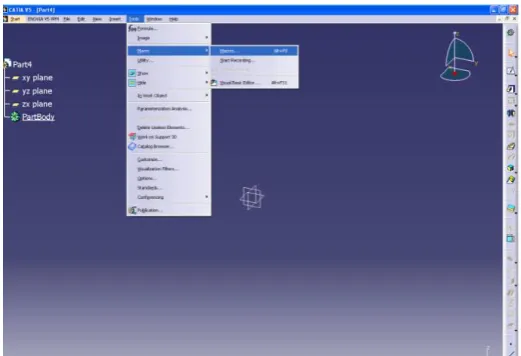
A CAT Script macro is written in a language similar to the Visual Basic language. One can record a CAT Script macro, then run it later on or write it from scratch. The recommended method is to start from a record then, depending on needs, edit and modify the pre-recorded macro. The purpose of writing macros can be user interface automation, launching programs, file management, text processing, drawing generation, report generation etc. When one record a macro, software’s each task’s steps are recorded and stored in a programming language called Visual Basic (actually Visual Basic for Applications or VBA). To record the macros, we have to go to tools, Macros, start recording as shown in figure below.
Figure 4. Screen short of Start with Macro
The sample of recorded macro is as shown below,
Language="VBSCRIPT"
Sub CATMain ()
Dim PartDocument1 'As Document Set documents1 = CATIA.Documents
Set partDocument1 = documents1.Add("Part")
Dim part1 'As Part
Set part1 = partDocument1.Part
Dim bodies1 'As Bodies Set bodies1 = part1.Bodies
Dim body1 'As Body
Set body1 = bodies1.Item("PartBody")
Dim sketches1 'As Sketches Set sketches1 = body1.Sketches
451 Dim reference1 'As Reference
Set reference1 = originElements1.PlaneYZ
Dim sketch1 'As Sketch
Set sketch1 = sketches1.Add(reference1)
This programming language can be examined and edited to further customize a macro. Macros will always execute the same steps exactly as they were recorded. In order to make macros more flexible some editing of the VBA code is required.
Once the command for recording is registered, it will ask for file name and path to save the file as shown below.
Figure 5. Screen short of save macro.
After giving necessary inputs, say start. One has to start making model of as per the regular procedure. The whole process of making model will be recorded in the form of VB Script and saved at the given location. This information can be used for further modification of model as and when needed. To edit the macros, one can follow the given path as Tools>Macros>Edit.
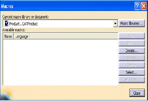
When we follow the given path, window as shown in figure 6 will appear.
Figure 6. Screen short of open, edit and run the Macro.
VI. SAMPLE MACRO TO READ VALUES
FROM MS EXCEL:-
The sample program to read the values from Excel is as shown below.
Language="VBSCRIPT"
Sub CATMain()
Dim objApp, objWbs, objWorkbook, objSheet
Set objApp = CreateObject("Excel.Application") Set objWbs = objApp.WorkBooks
objApp.Visible = False
Set objWorkbook = objWbs.Open("C:\Users\Rajesh Pansare\Desktop\Pansare Project\Output\Reference.xls")
Set objSheet = objWorkbook.Sheets("Sheet1") MsgBox objSheet.Range("A1").Value
'MsgBox A
A = objSheet.Range("A1").Value objWorkbook.Close False
objWbs.Close objApp.Quit
'Set objSheet = Nothing 'Set objWorkbook = Nothing
'Set objWbs = Nothing 'Set objApp = Nothing MsgBox "Done"
After editing the program say Run. The same model will be created but as per the parameters given in Excel file.
VII.
RESULT
Once all necessary input parameters are given to the MS Excel worksheet which is required for the design of centrifugal pump, the calculations are done in MS Excel and the design report is generated automatically. One can select the macros for individual component and if we run it, the component model will be generated automatically in CATIA.
Following are the major parts of centrifugal pump considered in above said work,
Volute Casing Suction Pipe Delivery Pipe
Impeller452 By this way all parts will be generated using recorded macros and saved in specified folder. Some of them are as shown in figures below.
If we select the macro for Casing and run, the updated view of Casing with required dimensions will get generated as shown in figure 7. The Casing will be saved at given location.
Figure 7. Snapshot of Casing Generated in CATIA
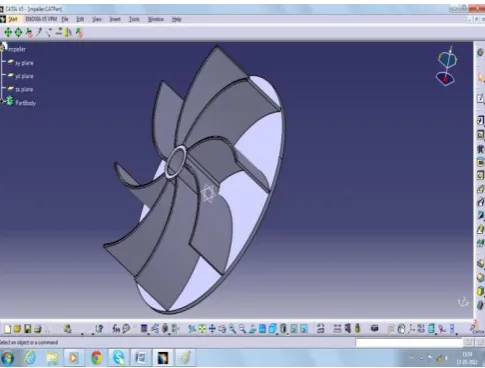
If we select the macro for Impeller and run, the updated view of Impeller with required dimensions will get generated as shown in figure 8. The Impeller will be saved at given location.
Figure 8: Snapshot of Impeller Generated in CATIA
If we select the macro for Assembly and run, the updated view of Assembly with required dimensions will get generated as shown in figure 9. The Assembly will be saved at given location.
Figure 9. Snapshot of Assembly Generated in CATIA
Similarly 2D drawings can be generated by macros and can be used on shop floor. The process related to generation of 2D drawings is not included in this paper. This shows that the whole process can be automated using macros.
VIII. CONCLUSION
With the presented work, author has shown how macros can be used to automate various tasks in the design process. Using these macros one can read the values from MS Excel in CATIA V5 and can use these values as parameters for generation of model. Hence lot of time and cost involved in the design process is saved. Also quality of the design process is improved and maintained because the knowledge base is created for the design of component. Author has tried to do the necessary design calculations in the Microsoft excel. Use these values for model generation using macros. The system will give 3D models of the Centrifugal Pump along with all its components. It also gives 2D drawings of the Centrifugal Pump. It generates complete design report along with all the inputs and parameters. Hence with the presented work, author tried to give flexibility for design calculation outside of CATIA environment which may be useful at so many places.
IX. FUTURE SCOPE
The presented work shows how an automated design system can be used to capture and present knowledge extracted from performance, manufacturing and maintenance activities. This creates a better foundation for making decisions regarding conceptual design. Engineers can then change the design and directly assess the life cycle cost allowing fast iterations, based on knowledge from design, manufacturing and maintenance disciplines. Still there are some more scopes for improving the system as follows.
A system can be extended for various types of impellers, Casings etc.
A system can also be developed for multiple types of assemblies.
453
References
[1] Raleigh, Mindy Rodgers, Eli Lilly and Company, USA, “Macro Design Automation Tool (MDAT) – A methodology for storing macro design information, generating documentation and code templates, and automating parameter validation”, Paper 014-2011, Richard Schneck, BOGIER Clinical & IT Solutions [2] María Gloria Del Río-Cidoncha, Juan
Martínez-Palacios, Francisco Ortuño-Ortiz, "Task automation for modelling solids with Catia V5", Aircraft Engineering and Aerospace Technology, Vol. 79 Iss: 1, 2007, pp.53 – 59.
[3] m. Laudanski, m. Ruschitzka, j. Wrobel, “Parametric models of mould tools in catiav5”, Fourth International Seminar and Workshop, 7th – 9th October 2004, Poland.
[4] Guk-Heon Choi, Duhwan Mun and Soonhung Han, " Exchange of CAD Part Models Based on the Macro-Parametric Approach”, International Journal of CAD/CAM Vol. 2, No. 1, pp. 13~21 (2002.)
[5] Byungchul Kim and Soonhung Han, “Integration of history-based parametric translators using the automation APIs”, Int. J. Product Lifecycle Management, Vol. 2, No. 1, 2007.
[6] Richard Cozzens, Southern Utah University, “Advanced CATIA V5 workbook, Knowledge ware and workbench”, Releases 12 & 13.
[7] Aurel MITRACHE, Constantin ISPAS, Miron
ZAPCIU, “COLLABORATIVE DESIGN