© Copernicus GmbH 2004
Advances in
Radio Science
On UWB beamforming
T. Kaiser
Duisburg-Essen University, Faculty of Engineering, Department of Communication Systems, Bismarckstraße 81,
47048 Duisburg, Germany
Abstract.
Ultra-Wideband (UWB) communication
sys-tems and Multi-Input-Multi-Output (MIMO) techniques rank
among the few emerging key technologies in wireless
com-munications.
For that reason the marriage of these two
complementary approaches should deserve attention.
Appar-ently, the extremely large ultra-wide bandwidth creates rich
multipath diversity which calls, at a first glance, additional
antenna elements into question. However, another point of
view is as follows. The attenuation by solid materials usually
increases with increasing frequency; e.g. frequencies above,
say, 10 GHz are considered to be blocked by walls etc. Since
UWB can occupy more than 7 GHz of bandwidth (according
to FCC regularisation) the performance of a communication
link can be physically extended only by adding spatial
infor-mation, i.e. multiple antennas, even if such extension may
play a minor role. From this point of view UWB& MIMO
presents an upper physical bound for indoor communications
and is therefore at least worth to be investigated. In order to
see the forest for the trees, we will focus in this limited
con-tribution on beamforming among all alternative MIMO
tech-niques (like space time coding or spatial multiplexing).
1
Introduction
In order to avoid strong interference of conventional
narrow-band transmission systems by ultra-widenarrow-band signals, the
power spectral density of UWB systems is fairly limited,
which leads – despite the enormous bandwidth – to a rather
restricted coverage. This weakness is opposite to one of the
main strengths of MIMO techniques; they are able to
in-crease the range. Such a reversal indicates the potential of
a marriage of these two complementary techniques.
Numerous other benefits can be envisaged. For
exam-ple, the capability of MIMO systems to spatially distinguish
among wavefronts impinging from different directions not
Correspondence to: T. Kaiser
([email protected])
only facilitates the equalizer design of UWB systems by
re-duction of delay spread, but rather enables a further increase
of data rate – Gbit/s over air becomes feasible. Moreover,
by MIMO techniques, narrowband and broadband interferers
can be spatially suppressed so that the number of concurrent
users might be significantly increased. Last but not least a
reduction of electromagnetic radiation can be expected from
UWB & MIMO, which in turn may also save battery life.
However, a large number of different challenges do resist.
For example, digital beamforming seems to be prevented
due to the extremely high sampling rate. In contrast, analog
beamforming requires adjustable true time delays, such
de-lays exhibit noticeable tolerance and therefore less precision.
Besides these technology barriers, numerous challenges have
to be overcome in fundamental processing of UWB signals
by MIMO techniques.
2
An analogy
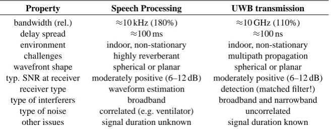
Without reinventing the wheel, some ideas can be borrowed
from speech or also from radar processing. The following
table shows the similarities and differences of broadband
beamforming for speech processing and UWB
communica-tion systems.
164
T. Kaiser: On UWB beamforming
Table 1. An analogy between speech processing and UWB transmission.
Property
Speech Processing
UWB transmission
bandwidth (rel.)
≈
10 kHz (180%)
≈
10 GHz (110%)
delay spread
≈
100 ms
≈
100 ns
environment
indoor, non-stationary
indoor, non-stationary
challenges
highly reverberant
multipath propagation
wavefront shape
spherical or planar
spherical or planar
typ. SNR at receiver
moderately positive (6–12 dB)
moderately positive (6–12 dB)
receiver type
waveform estimation
detection (matched filter!)
type of interferers
broadband
broadband and narrowband
type of noise
correlated (e.g. ventilator)
uncorrelated
other issues
signal duration unknown
signal duration known
be moderately positive, say a 6–12 dB. This can be achieved
either in case of limited range or by spreading techniques.
All these mentioned aspects show the similarities between
speech and UWB spatial processing. The main differences
result from the fact that the UWB receiver knows the
prin-cipal waveform whereas in speech processing not only the
waveform is completely unknown but also when speech
be-gins and when it ends. From this point of view, UWB seems
to be easier to deal with because the transmit signal can be
designed adequately. For example, in order to estimate the
direction-of-arrival
θ
of an impinging wavefront (see Fig. 1),
the transmit signal can be repeated periodically so that at the
receiver the sampling rate can be distinctly reduced by
al-most arbitrary low undersampling techniques. Moreover, for
UWB transmission a matched filter (MF) can be principally
deployed that further boosts up the SNR. However, this
ap-proach tends to be a bit overrated, since in dense UWB
mul-tipath environments numerous reflections occur and each
in-dividual reflection will modify the transmitted impulse shape
simply because of the non-flat frequency response of the
re-flective material. One last major difference concerns the kind
of noise and interferers. While in speech processing
broad-band interferers dominate and the noise is most often
cor-related (e.g. ventilator), in UWB transmission the
interfer-ers can be broadband as well as narrowband and the noise is
mainly of thermal type and hence uncorrelated.
In conclusion, because of its affinity, some concepts – like
broadband beamforming – can be borrowed from speech
pro-cessing.
3
Broadband beamforming
As mentioned previously we will focus on beamforming of
UWB signals. The following figure illustrates a conventional
filter and sum beamformer.
Basically, each filter can be substituted by a delay in order
to compensate for the different signal travel time among the
antenna elements and to coherently summing up all branches.
This so-called array gain enhances the SNR by a factor of
N
(or 10 log
10
(N )
on a decibel scale) under perfect conditions.
Property Speech Processing UWB transmission
bandwidth(rel.) 10kHz(180%) 10GHz(110%)
delayspread 100ms 100ns
environment indoor,non-stationary indoor,non-stationary
challenges highlyreverberant multipath propagation
wavefrontshape sphericalorplanar sphericalorplanar
typ. SNRat receiver moderatelypositive(6-10dB) moderatelypositive(8-12dB)
receivertype waveformestimation detection(matchedlter!)
typeofinterferers broadband broadbandandnarrowband
typeofnoise correlated(e.g. ventilator) uncorrelated
other issues signaldurationunknown signaldurationknown
Table1: Ananalogybetweenspeech processingandUWBtransmission
tiobetweenantennaapertureandtransmitter-receiver
distance. Inorder to guaranteeauseful transmission,
thesignaltonoiseratioatthereceiverhastobe
mod-erately positive, say a6-12 dB. This canbe achieved
either in case of limited range or by spreading
tech-niques.
All these mentioned aspects show the similarities
betweenspeechandUWBspatialprocessing. Themain
dierencesresultfromthefactthat theUWBreceiver
knowsthe principal waveform whereasin speech
pro-cessing notonlythe waveformis completely unknown
but also when speech beginsand when itends. From
thispointofview,UWBseemstobeeasiertodealwith
becausethetransmitsignalcanbedesignedadequately.
Forexample,inordertoestimatethedirection-of-arrival
ofanimpingingwavefront(seeFig. 1),thetransmit
signal canbe repeated periodically sothat at the
re-ceiver thesampling rate canbe distinctly reduced by
almostarbitrarylowundersamplingtechniques.
More-over,forUWBtransmissionamatchedlter(MF)can
beprincipallydeployedthatfurtherboostsuptheSNR.
However, this approach tends to be a bit overrated,
since in dense UWB multipath environments
numer-ousreectionsoccurandeachindividualreectionwill
modifythetransmittedimpulse shapesimply because
ofits non-atfrequencyresponse. Onelast major dif-ferenceconcernsthekindofnoiseandinterferers. While
in speech processing broadband interferers dominate
andthenoiseismostoftencorrelated(e.g. ventilator), inUWBtransmissiontheinterfererscanbebroadband
aswellasnarrowbandandthenoiseismainlyof
ther-maltypeandhenceuncorrelated.
Inconclusion,becauseofitsaÆnity,someconcepts
-likebroadbandbeamforming-canbeborrowedfrom
speech processing.
3. BROADBAND BEAMFORMING
As mentioned previouslyhere we will focus on
beam-forming of UWB signals. The following gure
illus-tratesaconventionallterandsumbeamformer.
g N
(t) y
N (t)
g 2
(t) y
2 (t)
g 1
(t) y
1 (t)
y(t) x(t)
Figure 1: Alterandsumbroadbandbeamformer
Basically, the ltercan be substituted by delay in
ordertocompensateforthedierentsignaltraveltime
among the antenna elements and to coherently
sum-ming up all branches. This so-called array gain
en-hances the SNR by a factor of N (or 10log 10
(N) on
adecibelscale)underperfect conditions. However,
in-terfererscannotbesuppressedonlybydelays. Forthat
reason,theuseofltersbecomesjustied. Fig. 2shows
thebeampatterndenedas
B(; 0
)=max t
jy(t;; 0
)j 2
forafamilyofsinusoidalsignals
x(t)=sin(2ft); f =3:1GHz:::10:6GHz
and N =8 antennas, asteering direction of 0
=0 Æ
,
an antennaspacingd= c
=2,where c
=c 0
=f c
, c 0
is
speedoflightandf c
=6:85GHzisthecenterfrequency
Fig. 1. A filter and sum broadband beamformer.
However, interferers cannot be suppressed only by delays.
For that reason, the use of filters becomes justified. Figure 2
shows the beampattern defined as
B(θ, θ
0
)
=
max
t
|
y(t, θ, θ
0
)
|
2
for a family of sinusoidal signals
x(t )
=
sin
(
2
πf t ),
f
=
3
.
1GHz
...
10
.
6GHz
and
N
=
8 antennas, a steering direction of
θ
0
=
0
◦
, an
antenna spacing
d
=
λ
c
/
2, where
λ
c
=
c
0
/f
c
,
c
0
is speed of
light and
f
c
=
6
.
85 GHz is the center frequency according to
FCC
1
-regularisation.
Observe that while the location of the mainlobe is
frequency-independent, the locations of the sidelobes and the
nulls are frequency-dependent. This means that broadband
interferers cannot be completely suppressed by a simple
de-lay and sum beamformer. Filters represent a remedy and
al-low an almost arbitrary high interferer cancellation just by
adequately increase of the filter orders. In principle,
conven-tional beamformer techniques (e.g. the minimum variance
T. Kaiser: On UWB beamforming
165
3
accordingtoFCC 1 -regularisation.
−90
−45
0
45
90
3.1
5
6
7
8
9
10.6
x 10
9
−20
−10
0
10
20
f mainlobe sidelobes B(; 0 ) dBFigure 2: Beampattern of a delay and sum broadband beamformer
Observethat while thelocationofthemainlobe is
frequency-independent, the locations of the sidelobes
andthenullsarefrequency-dependent. Thismeansthat
broadbandinterfererscannotbecompletelysuppressed
by asimpledelayandsumbeamformer. Filters
repre-sent a remedy and allow an almost arbitrary high
in-terferercancellationjust by adequatelyincreaseofthe
lter orders. In principle, conventional beamformer
techniques (e.g. the minimum variance distortionless
beamformer(MVDR))can bedeployedinorderto
de-signthelterandsumbeamformersimplyby
calculat-ing the weight vector for a set of suitable frequencies
andtransformingtheresultingweightmatrixintotime
domain.
UWB measurements have shown, at least under
line-of-sight(LOS)conditions,thepropagationof
indi-vidualechoesarrivingatthereceiverin so-called
clus-ters(seeforexamplethedescriptivevideosat[4]). Due
to their ultrashort duration, these echoes are
resolv-ableintimesothat theyalsobecomeresolvablein
an-gle; hence, the direction-of-arrival can be principally
estimated. Moreover, the recorded signals seem tobe
delayedreplicasofeachothersothatbeamforming
be-comesfeasible. Evenforaspacingofafewten
centime-ters,therelevantechoesseemtobestonglycorrelated.
Inaddition,asmallspacing(e.g. 4cm)doesnot cause
seriouscoupling[3].
(Ultra)-broadbandbeamformingoersanadditional
benet opposite to narrowband beamforming.
Nar-rowband beamforming suers from so-called grating
lobes. They occur for antenna spacingsd larger than
c
=2andtheyleadtoanambiguityofthe
direction-of-arrival. Forthatreason,commonnarrowbandantenna
elementsshowaspacingofhalvethecarrierwavelenght
1
FederalCommissionforCommunications
orevensmallerthanthis. Takingintoaccountthatthe
mainlobewidthdependsnotonlyonthenumberof
an-tennas but also from the spacing, narrowbandbeams
canonly benarrowedbyincreasingthenumber of
an-tennas. In turn, in (ultra)-broadband processing also
thespacing can beincreased further without
ambigu-ity. Inordertoillustratethisfact,thefollowinggures
(Fig. 3-6) show the squaredmagnitude of the
beam-former output and the beampattern for an antenna
spacing d = c
in case of two antennas, lower f l
=
3:1GHz and upper cut-o frequencies f u
= 10:6GHz
(!f c
=6:85GHz),andaninputsignalx(t)=e j2f
c t
(narrowband)or x(t)= e 2((f u f l )t) 2 e j2f c t (broad-band).
−90
−45
0
45
90
0
0.5
1
1.5
x 10
−9
0
1
2
3
4
5
jy(t;)j 2 t=[ns]Figure3: Squared magnitudeof narrowbandbeamformer outputford=c,N =2
−90
−45
0
45
90
−20
−15
−10
−5
0
max t 20log 10 y(t;) max y(t;)Figure4: Narrowbandnormalizedbeampatternford=c, N =2inlogarithmicscale
Itcanbeseenthatthenarrowbandbeamformerwill
suerfromthementionedambiguitysinceitcannot
dis-tinguishamongthe threepossible direction-of-arrivals
Fig. 2. Beampattern of a delay and sum broadband beamformer.
distortionless beamformer (MVDR)) can be deployed in
or-der to design the filter and sum beamformer simply by
calcu-lating the weight vector for a set of suitable frequencies and
transforming the resulting weight matrix into time domain.
UWB measurements have shown, at least under
line-of-sight (LOS) conditions, the propagation of
individ-ual echoes arriving at the receiver in so-called
clus-ters (see for example the descriptive videos at Whyless,
www.whyless.org/public/wp5.htm). Due to their ultrashort
duration, these echoes are resolvable in time so that they also
become resolvable in angle; hence, direction-of-arrival
esti-mation can be principally performed. Moreover, the recorded
signals seem to be delayed replicas of each other so that
beamforming becomes feasible. Even for a spacing of a few
ten centimeters, the relevant echoes seem to be stongly
corre-lated. In addition, a small spacing (e.g. 4 cm) does not cause
serious coupling (Sibille and Bories, 2003).
(Ultra)-broadband beamforming offers an additional
bene-fit opposite to narrowband beamforming. Narrowband
beam-forming suffers from so-called grating lobes. They occur
for antenna spacings
d
larger than
λ
c
/
2 and they lead to
an ambiguity of the direction-of-arrival. For that reason,
common narrowband antenna elements show a spacing of
half the carrier wavelength or even smaller than this.
Tak-ing into account that the mainlobe width depends not only
on the number of antennas but also on the spacing,
narrow-band beams can only be further narrowed by increasing the
number of antennas. In turn, in (ultra)-broadband
process-ing also the spacprocess-ing can be increased further without
ambi-guity. In order to illustrate this fact, the following figures
(Figs. 3–6) show the squared magnitude of the beamformer
output and the beampattern for an antenna spacing
d
=
λ
c
in case of two antennas, lower
f
l
=
3
.
1 GHz and upper
cut-off frequencies
f
u
=
10
.
6 GHz (
→
f
c
=
6
.
85 GHz),
and an input signal
x(t )
=
e
−j2
πf
c
t
(narrowband) or
x(t )
=
e
−2
π((f
u
−
f
l
)t )
2
e
−j2
πf
c
t
(broadband).
It can be seen that the narrowband beamformer will
suf-fer from the mentioned ambiguity since it cannot distinguish
accordingtoFCC 1 -regularisation.
−90
−45
0
45
90
3.1
5
6
7
8
9
10.6
x 10
9
−20
−10
0
10
20
f mainlobe sidelobes B(; 0 ) dBFigure 2: Beampattern of a delay and sum broadband beamformer
Observe that whilethe location of the mainlobeis
frequency-independent, the locations of the sidelobes
andthenullsarefrequency-dependent. Thismeansthat
broadbandinterfererscannotbecompletelysuppressed
byasimpledelay andsumbeamformer. Filters
repre-sent aremedy and allowan almost arbitraryhigh
in-terferercancellationjust byadequatelyincreaseofthe
lter orders. In principle, conventional beamformer
techniques (e.g. the minimum variance distortionless
beamformer(MVDR))canbedeployedinorderto
de-signthelterandsumbeamformersimplyby
calculat-ingthe weight vector fora set of suitable frequencies
andtransformingtheresultingweightmatrixintotime
domain.
UWB measurements have shown, at least under
line-of-sight(LOS)conditions,thepropagationof
indi-vidualechoesarrivingatthe receiverinso-called
clus-ters(seeforexamplethedescriptivevideosat[4]). Due
to their ultrashort duration, these echoes are
resolv-ableintimesothattheyalsobecomeresolvablein
an-gle; hence, the direction-of-arrival can be principally
estimated. Moreover, the recordedsignals seemto be
delayedreplicasofeachothersothatbeamforming
be-comesfeasible. Evenforaspacingofafewten
centime-ters,therelevantechoesseemtobestonglycorrelated.
Inaddition,asmall spacing(e.g. 4cm) doesnotcause
seriouscoupling[3].
(Ultra)-broadbandbeamformingoersanadditional
benet opposite to narrowband beamforming.
Nar-rowband beamforming suers from so-called grating
lobes. They occur forantenna spacings d larger than
c
=2andtheyleadtoanambiguityofthe
direction-of-arrival. Forthatreason,commonnarrowbandantenna
elementsshowaspacingofhalvethecarrierwavelenght
1
FederalCommissionforCommunications
orevensmallerthanthis. Takingintoaccountthatthe
mainlobewidthdependsnotonlyonthenumberof
an-tennas but also from the spacing, narrowbandbeams
canonlybenarrowedbyincreasingthe numberof
an-tennas. In turn, in (ultra)-broadband processing also
the spacing can beincreased further without
ambigu-ity. Inordertoillustratethisfact,thefollowinggures
(Fig. 3-6) show the squared magnitude of the
beam-former output and the beampattern for an antenna spacing d =
c
in case of two antennas, lower f l
=
3:1GHz and upper cut-o frequencies f u
= 10:6GHz
(!f c
=6:85GHz),andaninputsignalx(t)=e j2fct
(narrowband)orx(t)=e 2((f u f l )t) 2 e j2f c t (broad-band).
−90
−45
0
45
90
0
0.5
1
1.5
x 10
−9
0
1
2
3
4
5
jy(t;)j 2 t=[ns]Figure3: Squaredmagnitudeofnarrowband beamformer outputford=
c ,N =2
−90
−45
0
45
90
−20
−15
−10
−5
0
max t 20log 10 y(t;) maxy(t;)Figure4: Narrowbandnormalizedbeampatternford= c
,
N=2inlogarithmicscale
Itcanbeseenthatthenarrowbandbeamformerwill
suerfromthementionedambiguitysinceitcannot
dis-tinguishamongthe threepossible direction-of-arrivals
Fig. 3. Squared magnitude of narrowband beamformer output for
d
=
λ
c
,
N
=
2.
3
accordingtoFCC 1 -regularisation.
−90
−45
0
45
90
3.1
5
6
7
8
9
10.6
x 10
9
−20
−10
0
10
20
f mainlobe sidelobes B(; 0 ) dBFigure 2: Beampattern of a delay and sum broadband beamformer
Observethatwhile thelocationof themainlobe is
frequency-independent, the locations of the sidelobes
andthenullsarefrequency-dependent. Thismeansthat
broadbandinterfererscannotbecompletelysuppressed
byasimpledelayandsum beamformer. Filters
repre-senta remedy andallowan almost arbitraryhigh
in-terferercancellationjust byadequatelyincreaseof the
lter orders. In principle, conventional beamformer
techniques (e.g. the minimum variance distortionless
beamformer(MVDR))canbedeployedinorderto
de-signthelterandsumbeamformersimplyby
calculat-ing the weight vector for a set of suitable frequencies
andtransformingtheresultingweightmatrixintotime
domain.
UWB measurements have shown, at least under
line-of-sight(LOS)conditions,thepropagationof
indi-vidualechoesarrivingatthe receiverinso-called
clus-ters(seeforexamplethedescriptivevideosat[4]). Due
to their ultrashort duration, these echoes are
resolv-ableintimesothattheyalsobecomeresolvablein
an-gle; hence, the direction-of-arrival can be principally
estimated. Moreover,the recorded signals seem tobe
delayedreplicasofeachothersothatbeamforming
be-comesfeasible. Evenforaspacingofafewten
centime-ters,therelevantechoesseemtobestonglycorrelated.
Inaddition,asmallspacing (e.g. 4cm)doesnotcause
seriouscoupling[3].
(Ultra)-broadbandbeamformingoersanadditional
benet opposite to narrowband beamforming.
Nar-rowband beamforming suers from so-called grating
lobes. They occur for antenna spacings d largerthan
c
=2andtheyleadtoanambiguityofthe
direction-of-arrival. Forthatreason,commonnarrowbandantenna
elementsshowaspacingofhalvethecarrierwavelenght
1
FederalCommissionforCommunications
orevensmallerthanthis. Takingintoaccountthatthe
mainlobewidthdependsnotonlyonthenumberof
an-tennas but also from the spacing, narrowband beams
can onlybenarrowedby increasingthenumberof
an-tennas. In turn, in (ultra)-broadband processing also
the spacing canbe increasedfurther without
ambigu-ity. Inordertoillustratethisfact,thefollowinggures
(Fig. 3-6) show the squaredmagnitude of the
beam-former output and the beampattern for an antenna
spacing d = c
in case of two antennas, lower f l
=
3:1GHz and upper cut-o frequencies f u
= 10:6GHz
(!f c
=6:85GHz),andaninput signalx(t)=e j2fct
(narrowband)orx(t)=e 2((f u f l )t) 2 e j2f c t (broad-band).
−90
−45
0
45
90
0
0.5
1
1.5
x 10
−9
0
1
2
3
4
5
jy(t;)j 2 t=[ns]Figure 3: Squaredmagnitudeof narrowbandbeamformer outputford=c,N =2
−90
−45
0
45
90
−20
−15
−10
−5
0
max t 20log 10 y(t;) maxy(t;)Figure4: Narrowbandnormalizedbeampatternford=c, N =2inlogarithmicscale
Itcanbeseenthatthenarrowbandbeamformerwill
suerfromthementionedambiguitysinceitcannot
dis-tinguish among the threepossibledirection-of-arrivals
Fig. 4. Narrowband normalized beampattern for
d
=
λ
c
,
N
=
2 in
logarithmic scale.
among the three possible direction-of-arrivals
−
90
0
, 0
0
and
+
90
0
. In contrast, the broadband beamformer can clearly
resolve the 0
0
-DoA, because of no ringing of the received
impulse-shaped wavefront.
It is also of interest to study the effects caused by
increas-ing the spacincreas-ing and the number of antennas, see Figs. 7, 8.
Observe that extending the spacing leads to a narrowing
of the mainlobe, whereas more antennas not only further
decrease the mainlobe width but also increase the
main-to-sidelobe ratio. For example, in case of
d
=
2
λ
c
,
N
=
4,
the mainlobe width is approximately 15
0
so that with such a
linear array up to 180
0
/
15
0
=
12 spatially seperated users
can be ideally served.
Note also that for
d
=
2
λ
c
,
N
=
2 the array size is
8
.
76 cm, which might be implementable on a terminal. In
turn, for
d
=
2
λ
c
,
N
=
4 the array size becomes 26
.
28 cm,
166
T. Kaiser: On UWB beamforming
4−90
−45
0
45
90
0
0.5
1
x 10
−9
0
1
2
3
4
jy(t;)j 2 t=[ns]Figure 5: Squared magnitude of broadband beamformer outputford=c,N =2
−90
−45
0
45
90
−20
−15
−10
−5
0
max t 20log 10 y(t;) max y(t;)Figure6: Broadbandnormalizedbeampatternford=c, N =2inlogarithmic scale
90 0 , 0 0 and+90 0
. Incontrast,the broadband
beam-former can clearly resolve the 0 0
-DoA, because of no
ringingof thereceived impulse-shapedwavefront.
Itis alsoof interestto study the eectscaused by
increasingthespacingandthenumberofantennas,see
Fig. 7,8.
Observethat extendingthespacingleadstoa
nar-rowing of the mainlobe, whereas more antennas not
onlyfurther decrease the mainlobewidth but also
in-creasethemain-to-sideloberatio. Forexample,incase
of d = 2 c
, N = 4, the mainlobe width is
approx-imately 15 0
so that with such a linear array up to
180 0
=15 0
=12spatiallyseperateduserscanbeserved.
Notealso thatford=2 c
, N =2the arraysize is
8:76cm,whichmight beimplementableon aterminal.
In turn, for d = 2 c
, N = 4 the array size becomes
−90
−45
0
45
90
−20
−15
−10
−5
0
−90
−45
0
45
90
−20
−15
−10
−5
0
max t 20log 10 y(t;) maxy(t;)Figure7: Broadbandnormalizedbeampatternford=2c, N =2inlogarithmicscale
26:28cm,eventhisisimplementable-nowonalaptop.
4. CONCLUSION ANDFUTURE WORK
Inthiscontribution,wemotivatethemarriageofUWB
and multi-antenna technique by focussing on
beam-forming. Beside the complementary classes of
multi-antennaapproaches,i.e. spatialmultiplexingand
space-timecoding,therearenumerousopenissuesinthisnew
andhighlymulti-disciplinaryeld:
adjustablepreciseanalogtruetimedelays(oreven
lters)
directionof arrival,time delayestimation
beamformingforUWBchannels(model&data)
exploitingmultipathpropagationthancombating
pulseshaping,modulationforUWBmulti-antenna
systems
localisation, synchronisation with UWB
multi-antennasystems
UWB antenna arrays, where the frequency
re-sponsesamongtheelementsmaydier,butshould
overlap
broadbandbeamformingwithlownumberof
an-tennas
transmitbeamforming
Fig. 5. Squared magnitude of broadband beamformer output for
d
=
λ
c
,
N
=
2.
4
−90
−45
0
45
90
0
0.5
1
x 10
−9
0
1
2
3
4
jy(t;)j 2 t=[ns]Figure 5: Squaredmagnitude of broadband beamformer outputford=
c ,N =2
−90
−45
0
45
90
−20
−15
−10
−5
0
max t 20log 10 y(t;) max y(t;)Figure6: Broadbandnormalizedbeampatternford=c, N =2inlogarithmicscale
90 0 , 0 0 and+90 0
. Incontrast,thebroadband
beam-former can clearly resolve the 0 0
-DoA, because of no
ringing ofthe receivedimpulse-shaped wavefront.
It is alsoof interest tostudy the eectscaused by
increasingthespacingandthenumberofantennas,see
Fig. 7,8.
Observethatextendingthe spacingleadstoa
nar-rowing of the mainlobe, whereas more antennas not
only further decreasethe mainlobe widthbut also
in-creasethe main-to-sideloberatio. Forexample,incase
of d = 2 c
, N = 4, the mainlobe width is
approx-imately 15 0
so that with such a linear array up to
180 0
=15 0
=12spatially seperateduserscan beserved.
Note alsothat ford=2 c
,N =2the arraysize is
8:76cm,whichmightbe implementable on aterminal.
In turn, for d = 2 c
, N = 4 the array size becomes
−90
−45
0
45
90
−20
−15
−10
−5
0
−90
−45
0
45
90
−20
−15
−10
−5
0
max t 20log 10 y(t;) maxy(t;)Figure7: Broadbandnormalizedbeampatternford=2c, N =2inlogarithmicscale
26:28cm,eventhisisimplementable-nowonalaptop.
4. CONCLUSION AND FUTURE WORK
Inthiscontribution,wemotivatethemarriageofUWB
and multi-antenna technique by focussing on
beam-forming. Beside the complementary classes of
multi-antennaapproaches,i.e. spatialmultiplexingand
space-timecoding,therearenumerousopenissuesinthisnew
andhighlymulti-disciplinaryeld:
adjustablepreciseanalogtruetimedelays(oreven
lters)
directionof arrival,timedelayestimation
beamformingforUWB channels(model&data)
exploitingmultipathpropagationthancombating
pulseshaping,modulationforUWBmulti-antenna
systems
localisation, synchronisation with UWB
multi-antennasystems
UWB antenna arrays, where the frequency
re-sponsesamongtheelementsmaydier,butshould
overlap
broadbandbeamformingwithlownumberof
an-tennas
transmitbeamforming
Fig. 6. Broadband normalized beampattern for
d
=
λ
c
,
N
=
2 in
logarithmic scale.
4
Conclusion and future work
In this contribution, we motivate the marriage of UWB and
multi-antenna technique by focussing on beamforming.
Be-side the complementary classes of multi-antenna approaches,
i.e. spatial multiplexing and space-time coding, there are
nu-merous open issues in this new and highly multi-disciplinary
field:
– adjustable precise analog true time delays (or even
fil-ters)
– direction of arrival, time delay estimation
– beamforming for UWB channels (model & data)
4
−90
−45
0
45
90
0
0.5
1
x 10
−9
0
1
2
3
4
jy(t;)j 2 t=[ns]Figure 5: Squared magnitude of broadband beamformer outputford=c,N =2
−90
−45
0
45
90
−20
−15
−10
−5
0
max t 20log 10 y(t;) max y(t;)Figure6: Broadbandnormalizedbeampatternford=c, N =2inlogarithmic scale
90 0 , 0 0 and+90 0
. Incontrast,the broadband
beam-former can clearly resolve the 0 0
-DoA, because of no
ringingof thereceived impulse-shapedwavefront.
Itis alsoof interestto study the eectscaused by
increasingthespacingandthenumberofantennas,see
Fig. 7,8.
Observethat extendingthespacingleadstoa
nar-rowing of the mainlobe, whereas more antennas not
only furtherdecrease the mainlobewidth butalso
in-creasethemain-to-sideloberatio. Forexample,incase
of d = 2 c
, N = 4, the mainlobe width is
approx-imately 15 0
so that with such a linear array up to
180 0
=15 0
=12spatiallyseperateduserscanbeserved.
Note alsothatford=2 c
, N =2the arraysize is
8:76cm,whichmight beimplementableon aterminal.
In turn, for d = 2 c
, N = 4 the array size becomes
−90
−45
0
45
90
−20
−15
−10
−5
0
−90
−45
0
45
90
−20
−15
−10
−5
0
max t 20log 10 y(t;) maxy(t;)Figure7: Broadbandnormalizedbeampatternford=2c, N =2inlogarithmicscale
26:28cm,eventhisisimplementable-nowonalaptop.
4. CONCLUSION ANDFUTURE WORK
Inthiscontribution,wemotivatethemarriageofUWB
and multi-antenna technique by focussing on
beam-forming. Beside the complementary classes of
multi-antennaapproaches,i.e. spatialmultiplexingand
space-timecoding,therearenumerousopenissuesinthisnew
andhighlymulti-disciplinaryeld:
adjustablepreciseanalogtruetimedelays(oreven
lters)
directionof arrival,timedelay estimation
beamformingforUWBchannels(model&data)
exploitingmultipathpropagationthancombating
pulseshaping,modulationforUWBmulti-antenna
systems
localisation, synchronisation with UWB
multi-antennasystems
UWB antenna arrays, where the frequency
re-sponsesamongtheelementsmaydier,butshould
overlap
broadbandbeamformingwithlownumberof
an-tennas
transmitbeamforming
Fig. 7. Broadband normalized beampattern for
d
=
2
λ
c
,
N
=
2 in
logarithmic scale.
5
−90
−45
0
45
90
−20
−15
−10
−5
0
max t 20log 10 y(t;) maxy(t;)Figure8: Broadbandnormalizedbeampatternford=2 c
, N =4inlogarithmicscale
Of further interest is how the channel capacity is
af-fected by UWBtransmission. Firstworktowardsthis
relevant topic can be found in [5], [6]. It seems that
the numberof antennashas thesameimpactthanthe
bandwidth, infact, the equation known from
narrow-band MIMOsystemsfor theergodicchannelcapacity
C e
=BNlog 2
(1+SNR )
alsoholdsapproximatelytrueforUWBchannels. Such
resultfurthermotivatethemergeofthesetwokey
tech-nologiesinwirelesscommunications.
REFERENCES
[1] J.M.Cramer,R.A.ScholtzandM.Z.Win,On the
analysis of UWB communcation channels, IEEE
Military Communication Conference Proceedings
(MILCOM),Vol.2,1999,p.1191-1195
[2] H.Lee,H.Haan,Y.Shin,S.Im, Multipath
Char-acteristicsofImpulseRadioChannels,Proc.IEEE
VTC, May 15-18, 2000, Tokyo, Japan, pp.
2487-2491.
[3] A.SibilleandS.Bories,Space diversity forUWB
communications, EPMCC, April 22-25, 2003,
Glasgow,UK
[4] www.whyless.org/public/wp5.htm
[5] Z.Feng,T.KaiserandA.Czylwik,Onthe
Evalua-tionof Channel Capacityof Multi-AntennaUWB
Case, submitted to IEEE Transactions on
Com-munications
[6] Z.Feng,T.KaiserandA.Czylwik,Onthe
Evalua-tionof Channel Capacityof Multi-AntennaUWB
Indoor Wireless Systems{PartII: Frequency
Se-lectiveCase, submittedtoIEEE Transactionson
Communications