http://www.sciencepublishinggroup.com/j/ajset doi: 10.11648/j.ajset.20180302.13
ISSN: 2578-8345 (Print); ISSN: 2578-8353 (Online)
Development of Four-Zone Segmented Transitional Model
for Reciprocating Internal Combustion Engine Analysis
Using Gasoline
Ademola Adebukola Dare, Olanrewaju Bilikis Olatunde
*Department of Mechanical Engineering, Faculty of Technology, University of Ibadan, Ibadan, Nigeria
Email address:
*
Corresponding author
To cite this article:
Ademola Adebukola Dare, Olanrewaju Bilikis Olatunde. Development of Four-Zone Segmented Transitional Model for Reciprocating Internal Combustion Engine Analysis Using Gasoline. American Journal of Science, Engineering and Technology.
Vol. 3, No. 2, 2018, pp. 46-52. doi: 10.11648/j.ajset.20180302.13
Received: April 22, 2018; Accepted: August 28, 2018; Published: October 19, 2018
Abstract:
A four zone model based on the first law of thermodynamics has been developed for analysis of combustion in an internal combustion engine. The four zones included an unburned zone and two regions of burned zone, (namely burned gas1 and burned gas 2) and unburned burned zone described as a transitory zone which is a mixture of burned and unburned gases. Arbitrary constant for each of burn (CC2) and unburned (CC1) zone leakages in unburned burned zone was evaluated at optimally predetermined values of 0.005 and 0.00025 respectively, while mass fraction burned from burned gas1, x1 and burned gas 2, x2 were also evaluated at predetermined optimal values of 0.6 and 0.4 respectively. The model was used to analyse an SI engine operating with a gasoline fuel. The engine operating conditions were set at engine speed of 2000 rpm, -35bTDC ignition time and burn duration at 60°. The temperature distribution from the arbitrary constants (CC2, CC1, x1 and x2) for the newly developed four zone model was compared to the two zone model and literature experimental temperature value. The obtained indicated mean effective pressure (IMEP), thermal efficiency (η), cylinder pressure and emission characteristics from the developed model and those of two zone analysis were both compared with literature values.Keywords: Zones, Burn Duration, Ignition Delay, Spark Ignition Engine, Combustion, Emission
1. Introduction
The Spark-Ignition (Otto engines, gasoline and petrol engine) and the compression ignition (diesel engine) are the common examples of ICEs [1]. In internal combustion engine ICEs energy is released by burning or oxidizing fuel inside the engine. The fuel air mixture before combustion and the burned products after combustion are the actual working fluids. Basic mechanism of ICE has not changed till date since its invention. Major difference between modern day engine and ones built ages ago are improved reliability, thermal efficiency and emission level. Through the years, researches on ICE were directed and are still aimed towards improving thermal efficiency, emission rate and noise reduction as well as vibration. Thermal efficiency has increased from 10 to 50% today while emission is 5% of what it was 40years ago [2]. The internal combustion engine
is being used widely, variety of emission it produces and effects have being discussed by many researchers, [3-7].
made in the use of simulation model to achieve new engine ideas and technological advancement by increasing the number of zones being analysed.
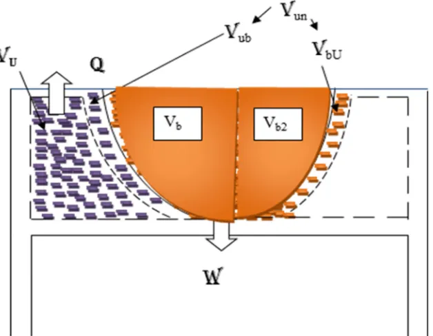
In the present study, a four zone model was developed for performance analysis, see Figure 1 for model geometry. The model which had unburned zone consisting of the fresh charge, volume of which is represented as Vu, mixture of
burned and unburned gases consisting of infiltration from both unburned and burned zones, Vun and partitioned burned
zones into burned zone1, Vb1and burned zone2, Vb2, by virtue
of uneven mixture proportion in the chamber leading to use of varying mass fraction rate of each burned zone and also varying the heat transfer coefficient to get the pressure, temperature, indicated mean effective pressure, thermal
efficiency and emission fraction readings.
2. Method
2.1. Mathematical Model
The 4-zone thermodynamic model being developed for this study consisting of unburned, two burned zones and transitory zones is shown in Figure 1. The burned zones divided into burned zone1 and burned zone2 by virtue of uneven mixture proportion in the chamber, while the transitory zone is formed by infiltration from the unburned and burned zones.
Figure 1. Geometry Representing the Four Zones (unburned zone, Unburned burned zone and burned zone1 and Burned2 Zone) In Combustion Chamber.
Vun is the addition of volume of unburned gases in
unburned burned zone, Vub and volume of burned gases in
unburned burned zone, Vbu that is,
The model equations are developed by applying the first law of thermodynamics to each zone as detailed below.
The rate of change of mass within any open system is the net flux of mass across the system boundaries, i.e.
∑ (1) The mass flux in the combustion chamber at any instant can be expressed as
(2)
where, mu is mass of unburned mixture, mb is mass of burned
gas, mb2 is mass of infiltration from burned zone and mun is
mass of mixture of burned and unburned gases.
Based on the application of the first law of thermodynamics to an open system, the energy equation is written as,
∑ (3) where, E, Q and W are internal energy of the cylinder mixture, heat exchange of content with cylinder wall and work done on piston by cylinder charge respectively. Equation (3) is thus applied to each of compression, expansion and combustion phases of the internal combustion engines as follows:
2.1.1. Compression and Expansion Processes
For the combustion and expansion phases, eqn. (3) is transformed to
= (4)
Now
= = m . ! (5)
" # [
% &']
(6)
By employing the ideal gas equation, PV = mRT, then
) &' ' * &
(7)
The cylinder composition is assumed frozen during compression and expansion processes i.e. *≅ 0
- ./ 0&' & 1 (8)
2.1.2. Combustion Process
During the combustion process, there will be three zones namely unburned, burned and infiltration from burned zone in the cylinder. The energy equation (Eqn. 3) is applied to each separately as detailed below
(i) Unburned zone
The energy equation for this zone is given as
232 4 2 p4%2 6 72 02 72 28 (9)
9 :
9; <== >?@?A ><BC DE& mu - mass unburned
mb2 – mass infiltration from burned zone
mlu – mass leakage from unburned zone to the crankcase
Eqn. (9) can be re-expressed as
2 2 2 2 / 2. 21 + 2 2 (10)
By noting that
2 = − 6F− 0,2− 28− 6H (11)
Eqn. (10) becomes
I . 2= − 2− %2− & ' 6− & ' 02 − & ' 28 (12)
From the ideal gas equation, the following expression can be written
%2+%2 -= & ' 2+ & 2 (13)
By substituting eqn, (13) in eqn. (12) yields
2= " 2#,J,2 −
2+ K -! (14)
(ii) Burned zone1
The energy equation for this zone is given as
8 8 = 8− L %8+ ℎ 6− ℎ 0,8 − ℎ 82 (15)
Mass of gas in burned zone (mb) =mass fraction burned
(mx1) + mass infiltration from burned zone (mbu)
With / 8= 6F− 0,8− 821, where ml,b is mass
leakage from the burned zone to the crankcase, equation 15 is re-expressed as
I , 8= − 8− 8+72 6F− 6F− & ' 08− & ' 82 (16)
The ideal gas equation for this zone is expressed as
%8+ K -= & ' 8+ & 8 (17)
Substituting eqn. (16) into eqn. (17) thus yields
8= M
NOP,Q,O −
8+%8 -+ ℎ − ℎ 6F (18)
(iii) Burned zone 2
By using the same procedure adopted in the analysis of the burned zone, the energy equation can be rearranged to obtain burned zone 2 temperature derivative as below.
Similarly, temperature for infiltration from burned zone to burned zone 2 is written as,
8H= M
NORP,Q,OR −
8H+%8H -+ ℎ − ℎ 6H (19)
(iv) Transitory ( obtained from infiltration of burned and unburned gases) zone.
In the same vein the energy equation for the transitory zone is written as
2S 2S = 2S− L %2S+ 72 28+78 82+72S 02S (20)
mass in transitory zone (mun)= mass infiltration from the
unburned zone (mub)+ mass infiltration from burned zone
(mbu)
With / 2S= 28+ 82+ 8F+ 8H− 02S1 ,
where mlun is mass leakage from the transitory zone to the
crankcase, Eqn. (20) is re-expressed as
I , 2S= − 2S−) %2S− 28 − 82+
ℎ 28+ ℎ 82 (21)
The ideal gas equation for this zone is expressed as
%2S+ K -= & ' 2S+ & 2S (22)
2 = "
2S#,J,2S − + K
-+ ℎ −ℎ 28+ ℎ −ℎ 82! (23)
When the overall energy equation is considered then the pressure derivative is obtained as 9L
9; = {'K 9'9; +K' 9'9; +K' 9'9; +'K 9'9; + − 99; +:. − 99; +: − 99; +
− 82 + − 8H− 02− 08− 08H− 02S− %}/%
- (24)
2.2. Implementation of the Developed Model
The developed model was used to obtain the temperature and pressure history in a combustion chamber. The five major ordinary differential equations (ODEs), namely equations 14, 18, 19, 23 and 24 for Tu, Tb1, Tb2, Tun and P
were well arranged in a MATLAB program and used to describe the rates of change of the parameters with respect to crank angle. Equations 4-14 were used during compression and expansion phases while equations 15-23 were used during the combustion phase. Sub models including engine geometry, fuel data and air data inherent in the two-zone model as reported in [9] were used in analyzing the present four-zone model. By integrating these ODEs using the inbuilt function ODE45. m in MATLAB as solver, engine performance from start of compression to end of expansion is modeled and analysed.
The model was applied to an internal combustion engine with operating and combustion parameters details as contained in Table 1. In the analysis, consideration was given mass fraction ratio and mass infiltration into the transitory zone, such that predetermined optimal result were analysed for present case3.
In the analysis the mass infiltration into the transitory zone is such that:
mub= CC1* mu and mbu=CC2* mb
where CC1, fractional burnt leakage and CC2, fractional unburnt leakage are arbitrary constants.
Burned zone1 and burned zone2 have different mass burning rates, (x1, x2) using varying heat transfer coefficients, (h400, h450, h500),
Table 1. Engine Specifications for 2Zone model.
Parameter Value
Number of cylinder 4
Bore 0.1
Stroke 0.08
Compression ratio 10
Parameter Value
Equivalence ratio 0.8
Burn duration angle 60
Start of burning -35
Engine speed 1500RPM
[9]
Table 2. Engine Specifications for model evaluation.
Parameter Value
Number of cylinder 4
Bore 0.085
Stroke 0.078
Compression ratio 11
Displacement 1.018
Start of Combustion 21
End of Combustion 30
Engine speed 2000RPM
[11]
The performance parameters such as thermal efficiency (η) and indicated mean effective pressure (IMEP) as well as the emission fraction obtained using the developed model were compared with the standard two-zone model and both were compared to an experimental result from a four stroke, SI engine (EF7) running with CNG fuel, [11], engine geometry are shown in Table 2. Results for IMEP, η, Pressure and emission characteristics were presented graphically in figures 2 to 5 and tables 3and 4.
3. Results and Discussion
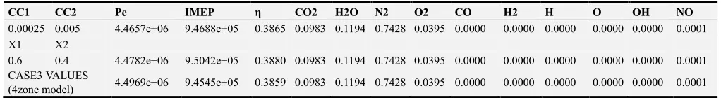
The conclusive results from both analyses of mass infiltration and mass fraction burn are used for analyzing the 4zone model. Extensive explanation of the derived mass infiltration and mass fraction analysis can be found in [10, 12] respectively. Table 3 shows the four-zone model values in comparison to optimal mass infiltration and mass fraction burn values.
Table 3. Four-zone model values in comparison to optimal mass infiltration and mass fraction burn values.
CC1 CC2 Pe IMEP η CO2 H2O N2 O2 CO H2 H O OH NO
0.00025 0.005 4.4657e+06 9.4688e+05 0.3865 0.0983 0.1194 0.7428 0.0395 0.0000 0.0000 0.0000 0.0000 0.0000 0.0001
X1 X2
0.6 0.4 4.4782e+06 9.5042e+05 0.3880 0.0983 0.1194 0.7428 0.0395 0.0000 0.0000 0.0000 0.0000 0.0000 0.0001
CASE3 VALUES
Table 4. Comparison of 4zone results from 2zone model, 3zone model and experimental results.
2zone model
Experimental values
3zone model using x1= 0.6 and x2=0.4
3zone model using
CC1=0.00025 and CC2=0.005
4zone Model using x1= 0.6 and x2=0.4 (h400), CC1=0.00025 and CC2=0.005
Pe 4.4358e+06 4.640e+06 4.5185e+06 4.4657e+06 4.4969e+06
Tbe 2305K 2800K 23157K 2.3241e+03 2.315e+03
IMEP 9.1635e+05 9.4847e+05 9.4688e+05 9.4545e+05
η 0.3741 - 0.3872 0.3865 0.3859
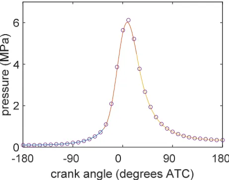
Figure 2. Pressure history for experimental Model (Omid, 2012). Figure 3. Pressure history for 2zone Model.
Figure 5. Pressure history for 4zone Model using x1= 0.6 and x2=0.4 (h400), CC1=0.00025 and CC2=0.005.
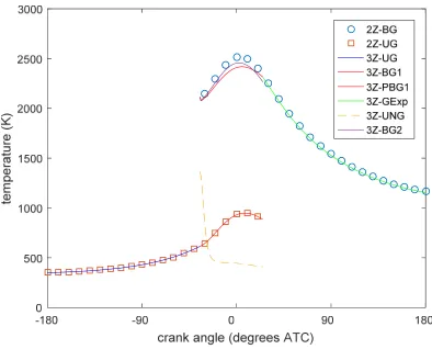
Maximum peak pressure of 4.4969MPa was observed using 4zone model. It could be inferred that the 4zone model is better at predicting pressure history, see table 3. Highest values of IMEP and η were observed using the 3zone segmented model (x1=0.6, x2=0.4). It was observed that the 4zone model temperature history is identical to the 2zone model, see figure 4.
A comparison of the experimental, 2zone, 3 zone and 4zone models results are presented in Table 4. Higher peak pressure values were observed for 4zone model which was 3.1% closer to experimental value as compared to the 2zone model which was 4.4% closer. This could imply an improved engine work estimate using the 4zone model. Higher peak temperature values were observed for 4zone model which was 17% closer to experimental value as compared to the 2zone model which was 18% closer. This could imply a better temperature distribution achieved using the 4zone model. Thermal efficiency and IMEP values were observed appreciably higher for the 4-zone model as compared with the 2-zone model.
4. Conclusion
A 4-zone model for prediction of performance of an internal combustion engine has been developed. The results obtained established that incorporating a new zone by dividing the burned zone into segments, comprising variable mass fraction burned coupled with an additional zone comprising mixture of unburned and burnt gases at a determined optimal range, the 4-zone model gave a better estimate of an internal combustion engine performance characteristics.
Nomenclature
W: work (J) P: pressure (Pa)
cv: specific heat at constant volume (J/kg/K)
cp: specific heat at constant pressure (J/kg/K)
h: enthalpy (J/kg) m: mass (kg)
Q: heat transfer rate across the system boundry into the system (J)
R: specific gas constant (J/kgK) T: temperature (K)
u : internal energy of material contained in the system (J/kgK)
v: volume (m3) θ: crank angle (0CA) mx: mass fraction burned
Subscripts
b1: burned zone1
u: unburned b2: burned zone 2 un: unburned burned v1: volume of fuel A
v2: volume of fuel B
l: leakage/blowby
mx1: mass burn rate for fuel A mx2: mass burn rate for fuel B
References
[1] John B. Heywood, 1988. Internal Combustion Engine Fundamentals. McGral Hill, Inc. New York series (11) Pp. 1. [2] C. R. Ferguson and Allan T. Kirkpatrick, 2016. Internal
Combustion Engines. Applied Thermosciences. Third Edition. John Wiley & Sons, Ltd.
[3] Sachin M. Kanawade, Anantraj D. Hamigi and Ravindra W. Gaikwad, 2010. Ecological Effect of Pollution. International Journal of Chemical Engineering and Applications, Vol. 1, No. 4. Pp. 332-335.
[4] Baryalai Tahzib and Lenka Zvijáková, 2012. Environmental Impact of Land Transport. Transfer inovácií. Issue 24. Pp. 70-77.
[5] V. Jurić, D. Županović, 2012. Ecological Impacts of Diesel Engine Emissions. Ecological Impacts of Diesel Engine Emissions. Pp. 151- 160.
[6] Yousef S. H. Najjar, 2011. Gaseous Pollutants Formation and Their Harmful Effects on Health and Environment. Ashdin Publishing Innovative Energy Policies Vol. 1. Pp. 1-8. [7] L. A. Jimoda, 2012. Effects Of Particulate Matter on Human
Health, The Ecosystem, Climate And Materials: A Review. Working and Living Environmental Protection Vol. 9, No 1. Pp. 27 – 44.
[9] D. R. Buttsworth., (2002). Spark Ignition Internal Combustion Engine Modelling using Matlab. Faculty of Engineering & Surveying Technical Reports.
http://www.usq.edu.au/users/buttswod/.
[10] A. Dare, O. S. Ismail and O. B. Olatunde, 2018. Development of Three-Zone Transitional Model for Reciprocating Internal Combustion Engine Analysis using Gasoline. Current Journal of Applied Science and Technology, (CJAST). Issue 25. Vol. 6. Pp. 1-11.
[11] Omid Asgari1, Siamak Kazemzadeh Hannani and Reza Ebrahimi, 2012. Improvement and experimental validation of a multi-zone model for combustion and NO emissions in CNG fueled spark ignition engine. Journal of Mechanical Science and Technology Issue 26 (4). Pp. 1205-1212.