EXPERIMENTAL AND NUMERICAL INVESTIGATION ON
LASER BENDING PROCESS
M. Hoseinpour Gollo*
Department of Mechanical Engineering, Faculty of Eng., University of Mohaghegh Ardabili, P.O.Box 173, Ardabil,Iran
H. Moslemi Naeini
Department of Mechanical Engineering, Tarbiat Modarres University, Tehran. Iran
N. B. Mostafa Arab
Department of Mechanical Engineering, Shahid Rajaee Teacher Training University, 16788-15811,Tehran, Iran
Received: 19/7/2011 Accepted: 29/8/2011 Online: 11/9/2011
ABSTRACT
Laser bending is an advanced process in sheet metal forming in which a laser heat source is used to shape the metal sheet. In this paper, temperature distribution in a mild steel sheet metal is investigated numerically and experimentally. Laser heat source is applied through curved paths in square sheet metal parts. Finite element (FE) simulation is performed with the ABAQUS/CAE standard software package. Material property of AISI 1010 is used in FE model and experiments. The aim of this study is to identify the response related to deformation and characterize the effect of laser power with respect to the bending angle for a square sheet part. An experimental setup including a Nd:YAG laser Model IQL-10 with maximum mean laser power of 500 W is used for the experiments to verify FE analysis results. It is observed that numerical results are relatively in good agreement with the experimental results. Results also show that increasing laser power increases the bending angle.
KEYWORDS:Laser forming, Temperature distribution, Finite element method
NOMENCLATURE
Expansion coefficient
:Surface emissivity
:Density
:
Yield stress Y
:
Specific heat p
c :
Elastic modulus of the plastic region E:
Heat transfer coefficient c
h :
Convection coefficient in bottom of the plate down
h :
Convection coefficient in top of the plate u
h :
Thermal conductivity k :
Temperature distribution in FEM contours NT11:
Rate of the heat per unit area q:
Sheet Thickness(mm) T:
Environment temperature T:
Sheet metal temperature s
T:
Displacement U3:
Scan Velocity(mm/s) V:
INTRODUCTION
Laser forming is a process of gradually adding plastic strain to a metal component to generate the desired shape. It can be used for forming straight bends in high strength metals such as titanium instead of hot brake forming. This process involves scanning a focused or partially defocused laser beam over the surface of a work piece to cause localized heating along the bend line. The sharp thermal gradients in the material cause the sheet to bend either toward or away from the laser source. The resulting deformation of the material, which is, bending toward the laser beam, is permanent. By repeating the laser forming process, either with overlapping or parallel scans, bend of desired angle and radius can be obtained. The bending angle is in the range of 0.5-1.5 degree in one pass. This is the increment of the process. Therefore, there is a better control on bending angle without any spring back effect. Eliminating the spring back in this process is a major advantage over mechanical bending. Large bending angles can be obtained by numerous laser passes.
Kyrasanidi et al. [1] introduced an analytical model for the prediction of distortions caused by the laser forming process through parametric investigation and process optimization. Zhang and Michaleris [2] have compared Eulerian approach with Lagrangian approach because both approaches can be applied in the modeling of laser forming processes, while Cheng and Lin [3] focused on simplified analytical solutions. Different thermo-mechanical simulations have been presented by Hu et al.[4], Shichun and Zhong [5], Zhang et al. [6] and Hsieh and Lin [7] but some of the earliest works on laser forming of sheet metal into two-dimensional shape are attributed to Namba [8, 9].
The laser forming process was first modeled by Vollertsen et al using both the finite difference method (FDM) and Finite element method (FEM) [10]. Vollertsen has suggested a semi empirical model to predict bending angle as a function of material and laser parameters [11, 12]. Kyrsanidi et al [13] have developed a numerical model of the laser forming process for steel by using a coupled transient thermal-structural FE analysis. Edwardson [14] presents an investigation into the two and three dimensional laser forming of metallic components.
In this paper, first a numerical model using FEM is proposed for simulating the laser bending process. It includes three dimensional nonlinear transient couple thermo-mechanical analysis taking into account the temperature dependency of the thermal and mechanical properties of the material. The results of this numerical model are then compared with the experimental results of the laser bending process performed with a Nd:YAG laser .
FINITE ELEMENT MODEL
The assumptions made for the numerical modeling are as follows:
Mises criterion is used as the yield criterion in the simulation process. In addition to these, the sheet metal is flat and free of residual stresses.
Element and Mesh
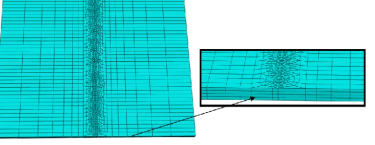
Three dimensional nonlinear coupled thermo-mechanical solid elements with eight nodes C3D8T are used for thermal and structure analysis. For the analysis, the same mesh model is used. As shown in Fig. (1), to achieve a good accuracy near the heat source, fine meshes are necessary. To reduce the run time, the coarse meshes are used far from the heat source and three elements are used across the thickness of the sheet to achieve appropriate accuracy. Moreover, the heat generated by plastic deformation is negligible because it is small compared with heat input by the laser beam. The structural analysis can then be decoupled from thermal analysis. The thermal analysis is done first with a three dimensional heat conduction equations to obtain temperature filed, and then the results are used as the thermal loading for the mechanical analysis.
Fig. 1. Metal sheet mesh general view.
Thermal Boundary Conditions
The thermal load is given in the form of thermal flux density which can be roughly expressed by a square shape function, and heat flux generated by the laser beam is applied only to the top surface of the sheet metal. The boundaries are modeled by natural heat convection and radiation. Convection
follows the Newton’s lawand the rate of the heat loss is Wm2:
)
(
T
T
h
q
c s
(1)Wherehcis the heat transfer coefficient, Ts is the sheet metal temperature and T the environment temperature, which is set as 25 ºC.
The rate of heat per unit area inWm2due to radiation is:
)
(
10
67
.
5
8T
4T
4q
s
(2)Where ε is the surface emissivity.
Mechanical Boundary Conditions
In mechanical analysis, necessary constraints are added to eliminate rigid body movement according to the fixture used in real experiments. The boundary conditions are zero displacement at one side of the sheet metal which is fully constrained and the other side is considered free.
Time Step
two adjacent is less than 15-20ºC. The analysis is performed up to the moment when the metal plate is cooled to room temperature.
Material Properties
Thermal properties (thermal conductivity, specific heat and convective heat transfer) and mechanical properties (modulus of elasticity, Poissonʼs ratio, density and yield stress) are temperature dependent
and shown in Tables(1and 2).
Table 1. Thermal properties of AISI 1010 [15] [16].
Table 2. Mechanical properties of AISI 1010 [15] [16].
T ºC
k
1 2 K Wm p C 1 1 K JKg 1 2 K Wm u
h hdown
0
51.9
450
100
51.1
---
7.64577
3.82242
200
49
519
9.04495
4.52248
300
46.1
557
10.0863
5.04315
400
42.7
599
10.33564 5.16782
500
39.4
662
10.52563 5.26282
600
35.6
749
10.73691 5.36845
700
31.8
846
10.89470 5.44735
800
26
950
11.0002
5.50010
1000
27.2
11.1744
5.58722
1500
29.7
400
T ºC
y(MPa)
E(Gpa)
(1061/C)0
290
200
10
100
260
200
11
300
200
200
12
450
150
150
13
550
120
110
14
600
110
88
14
720
9.8
20
14
800
9.8
20
14
1200
-
2
15
EXPERIMENTAL SETUP
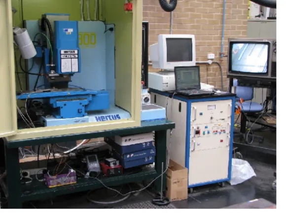
A Nd:YAG laser with maximum laser power of 500 W was used for experiments as shown in Figs. (2) and (3). The wave length of Nd:YAG laser light is 1064nm and operating with 6.3mm nominal beam diameter. The laser beam is transmitted by fibre optic beam delivery of 800 µm core to the workpiece surface. The experimental laser bending process has been arranged where the laser head is stationary and the workpiece located on the machine table may move in two directions x, y in the horizontal plane relative to the laser head which is aligned along the z axis.
As shown in Fig. (3) a CNC milling machine table was used for work table and placing the workpiece on the table and also to be able to program the bending path. The CNC milling machine table is 160x510mm with T-slots that facilitate fastening the workpiece on the table. The laser heat at the end of the fibre optic was mounted at the end of the immobilized spindle of the milling machine. The safety precaution for using the Nd:YAG laser is critical and the work table of the milling machine and laser head were concealed in a metal cabin as shown in Fig. (2) with a door for access. Shielding supports the safety of optical elements when operating in an industrial environment. The fumes and shielding gas (pure Argon) were evacuated by the exhaust fan mounted on top of the cabin. The cabin was equipped with a camera and light to be able to observe laser bending process on a television screen outside the enclosed cabin. The cabin is equipped with safety switches to stop the operation when the cabin door opens.
power meter was used to measure power. The short wave length of Nd: YAG laser light (1064nm) is more effective on heating sheet metal because more energy is absorbed by metallic surfaces. The investigation is on laser bending of 1mm thick mild steel sheet of St12 (AISI1010) which is a cold rolled low carbon steel. The size of the samples is 100x100 mm. The samples were cleaned using ethyl alcohol before laser bending. The bending of the samples was measured at 3 to 5 locations along the scanning path and their average was calculated. Material data are given in Tables 1and 2.
Fig. 2. The Nd:YAG laser rig with the X-Y table controller.
COMPARISON BETWEEN NUMERICAL AND EXPERIMENTAL RESULTS
The numerical results for the bending angle are compared with results obtained from experiments to verify the validity of the numerical simulation.
Fig. (4) shows the temperature field due to the first pass and NT11 is the parameter which shows temperature in FEM contours. Fig. (5) shows the distortion taking place after the first pass. This indicates that the two corners of the free end of the sheet are distorted more than the centre of the sheet. U3 is the parameter showing displacement in FEM contours.
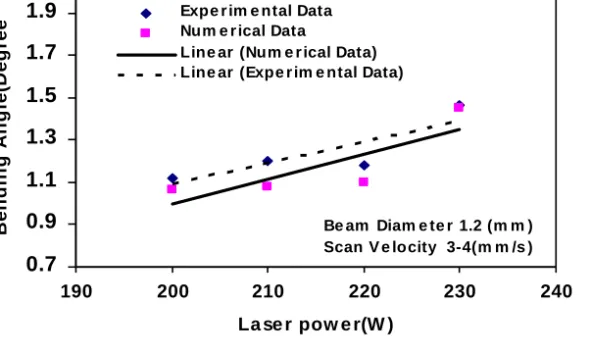
Numerical and experimental results are shown in Fig. (6). It can be seen that the numerical and experimental results are in reasonably good agreement. This Figure also shows that increasing the laser power increases the bending angle.
0.7 0.9 1.1 1.3 1.5 1.7 1.9
190 200 210 220 230 240
La se r pow e r(W )
B
e
n
d
in
g
A
n
g
le
(D
e
g
re
e
) Expe r im e ntal Data Num e r ical Data
Line ar (Num e r ical Data) Line ar (Expe r im e ntal Data)
Be am Diam e te r 1.2 (m m ) Scan V e locity 3-4(m m /s )
Fig. 6. Comparison between experimental and numerical results.
CONCLUSIONS
In this paper, a three dimensional FEM model for three dimensional thermo-mechanical simulation of the laser bending has been developed.
Experiments were conducted by Nd:YAG laser to validate the simulation results. A numerical model is proposed for simulating the laser forming process that includes the nonlinear transient coupled thermal-mechanical analysis with the temperature dependency of the thermal and mechanical properties of the material. The laser beam is modeled as a step-wise moving heat source.
Numerical result for bending angle is compared with that obtained from the experiments to verify the validity of the numerical model. The numerical and experimental results are relatively in good agreement. Increase in laser power led to an increase in bending angle.
ACKNOWLEDGEMENT
a
a
b
b
c
c
Fig. 4. Temperature contour plots of the formed plate, beam diameter=3.5mm, Q=1.8e7W/ m2,
Scan velocity=6 mm/s, single pass.
Fig. 5. Displacement contour plots of the formed
REFERENCES
[1] A.K. Kyrsanidi, T.B. Kermanidis and S.G. Pantelakis,“An analytical model for the prediction of distortions caused by the laser forming process”, J. Mater. Process. Technol., Vol. 104, pp 94–
102, (2000).
[2] L. Zhang and P. Michaleris, “Investigation of Lagrangian and Eulerian finite element methods for modeling the laser forming process”, Finite Elem. Anal. Des., Vol. 40, pp 383–405, (2004). [3] P. J. Cheng and S.C. Lin,” An analytical model to estimate angle formed by laser”, J. Mater.
Process. Technol., Vol. 108, pp 314-319, (2001).
[4] Z. Hu, R. Kovacevic and M. Labudovic, “Experimental and numerical modeling of buckling instability of laser sheet forming”, Int. J. Mach. Tools Manuf., Vol. 42, pp 1427-1439, (2002). [5] W. Shichun and J Zhong,“FEM simulation of the deformation field during the laser forming of
sheet metal”, J. Mater. Process. Technol., Vol. 121, pp 269-272, (2002).
[6] L. Zhang, E.W. Reutzel and P. Michaleris,”Finite element modeling discretization requirements for the laser forming process”, Int. J. Mech. Sci., Vol. 46, pp 623-637, (2004).
[7] H.S. Hsieh and J. Lin,“Thermal–mechanical analysis on the transient deformation during pulsed laser forming”, Int. J. Mach. Tools Manuf., Vol. 44, pp 191-199, (2004).
[8] Y. Namba, “Laser forming in space”, Proc. of Int. Conf. on Lasers, Las Vegas, NV, USA, pp 403-407, (1985).
[9] Y. Namba, “Laser forming of Metals and alloys”, Proc. of LAMP, Osaka, Japan, pp 601-606, (1987).
[10] F. Vollertsen, M. Geiger and W. Li, “FDM and FEM Simulation of laser forming: A Comparative Study”, Proc. of 4th Int. Conf. on Technology of plasticity, pp 1793-1798, (1993). [11] F. Vollertsen, “An Analytical Model for Laser Bending”, Lasers in Eng., Vol. 2, pp 261-276,
(1994).
[12] F. Vollertsen,“Mechanism and Models for Laser Forming”, Proc. of Laser assisted Net shape
Eng., Meisenbach Bamberg, Germany, pp 1345-359, (1994).
[13] A. K. Kyrsanidi, T. B. Kermanidis, and S. G. Pantelkis, “Numerical and Experimental Investigation of the Laser forming process”, Journal of Materials Processing Technology, Vol.
87, pp 281-290, (1999).
[14] S. Edwardson, “A Study into the 2D and 3D Laser Forming of Metallic Components”, PhD thesis, Laser Group Department of Engineering the University of Liverpool, UK, (2004)
[15] S. Brown and H. Song, “Finite element simulation of welding of large structures”. Journal of
Engineering for Industry, Vol. 114, No. 4, pp 441-451, (1992).