Research Journal
Volume 7, No. 19, Sept. 2013, pp. 48–54
DOI: 10.5604/20804075.1062360 Original Article
Received: 2013.06.12 Accepted: 2013.08.07 Published: 2013.09.06
THE USE OF OPTICAL SCANNER IN MEASUREMENTS OF COMPLEX SHAPE
OBJECTS
Barbara Juras1, Danuta Szewczyk1, Jerzy Sładek1
1 Laboratory of Coordinate Metrology, Mechanical Department, Cracow University of Technology, 24 War-szawska Str., 31-155 Kraków, Poland, e-mail: [email protected]; [email protected]; sladek@ mech.pk.edu.pl
ABSTRACT
The paper presents the topic of measurements of simple and complex shaped ob
-jects. Optical measurement method with the use of laser scanner was presented, as well as the issues of geometry measurements and shape assessment by the use of the
strategy of fitting to standard elements. The construction of a reference model for
given elements by measuring of malformed elements was shown. The given examples
confirmed the usefulness of presented optical method in the assessment of shape
com-patibility of real element with nominal one, as well as in the assessment of objects’ deformation.
Keywords: optical scanner, complex shape elements, reference model, shape compat
-ibility assessment.
INTRODUCTION
Measurements of dimensions and shape of elements are often the basis for assessment of possible objects loadings and elements using up. The analysis of the possibility of using differ -ent measurem-ent techniques in measurem-ents of complex shape objects is discussed by many authors [1, 6].
Among issues considered, special attention is paid to the problems of accuracy assessment of used measurement systems in relation to giv -en tasks [3, 4, 7, 10, 11].
A special place in this field is taken by a coordinate measuring technique, where for the geometry description coordinates of points lo -cated on the object of researches are used. Typi -cal coordinate systems include, among others, in contact techniques: coordinate measuring ma -chines, measuring arms with contact probes or laser trackers and in contactless systems: optical scanners or computed tomography.
ELEMENTS SHAPE ASSESSMENT BY
FITTING THEM TO STANDARD ELEMENTS
In coordinate metrology the analyzed shapes are often compared with simple elements, includ -ing the shapes, such as point, line, plane, circle, cylinder, cone, sphere and torus. For elements with a more complex shape the fitting is done us-ing CAD models. In the paper various ways of elements assessment depending on their geom -etry were presented. First, the elements with a relatively simple construction were considered, then plates with complex spatial geometry, and as a third example elements consisting of many con -nected profiles were used.
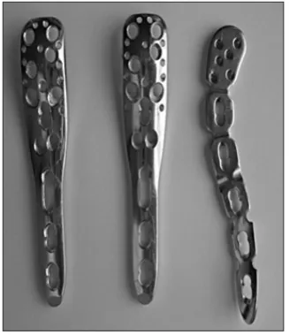
In this case, new plates are simple elements with oval or round holes. These holes have cham -fers for better fitting of mounting screws; the chamfers are visible in the pictures. Transfer of large forces and bending moments through the whole elements and fitting of plates to bones shape causes significant changes in their geome-try. Changes in plates’ shapes related to bones’ fu -sion and with loads transferring in case of longest plates is most commonly associated with their curvature. The assessment of the above men -tioned deformation is relatively simple. It is hard -er to change the object geometry spatially. Such a deformation has the element shown in Figure 2.
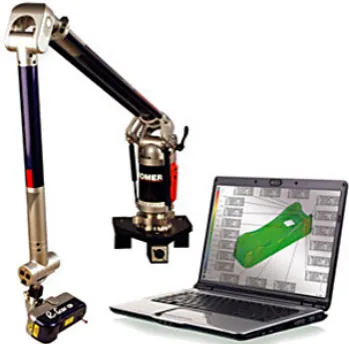
To assess the plate deformation was used the R-Scan RX2 optical measurement system coop-erating with Omega 2025 arm (Fig. 3).
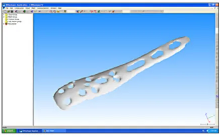
This system allows to collect point cloud map -ping the tested shape with use of a laser scanning probe. Data cleaning and filtering operations allow obtaining information on the size and shape of the measured object. The accuracy of used system and its usefulness in assessment of elements shape was analyzed in works [2, 3, 8, 9]. The tested object is shown in a form of point cloud in Figure 4.
3DReshaper software used for data process -ing allows, among other, to fit obtained points to certain basic geometric shapes such as: planes, cylinders or spheres. As a result of fitting, the as-sessment of the actual shape of measured surface can be done (Fig. 5).
Fig. 1. Fusion plates of simple geometry
Fig. 2. Spatial deformation of fusion plate
Fig. 3. OMEGA measuring arm of Romer company with R-Scan scanning probe
Fig. 4. Point cloud mapping the geometry of tested object
Fig. 5. The shape element assessment with the use of
best fit plane according to the least squares method
Deformation values in certain points are pre -sented in a form of a map. Distance values of measurement points and their distribution on the whole object can be read using the scale shown in a form of a graph in the left side of the diagram.
The shape assesment of complex geometry elements
-tially shaped elements taken into consideration are presented in Figure 6.
The considered elements have smooth holes, threaded with different diameters and different angles of hole axis in relation to the face plane.
Particular plates of similar geometry may dif -fer in small details, such as additional undercuts in the concave part (Fig. 7).
Fig. 6. Complex geometry elements
Fig. 7. Differences in elements shape
The plates tested had visible scratches. How -ever, they do not change the elements’ geom -etry significantly. To assess the shape change of such complex surfaces the optical scanner with 3DResaper software was used, as in the case dis
-cussed previously. The measuring system used allows for tested shape assessment in relation to the reference model. The standard shape can be obtained from the CAD model of the element or by measuring of the under-formed element. The way of model building based on the measurement and the element shape assessment is presented in the following part of this paper.
Building of a reference model
The first phase of the element shape assess-ment is to obtain the reference model. Because of the absence of the source CAD model, the model built on the basis of standard part measurements was adopted as a standard. Point cloud scanned on the plate is shown in Figure 8.
Due to the high reflectivity of the measured surface, during measurement appears some scat -ter of measurement points that requires their cleaning from noises. Points cleaned from noises allow to construct the model by applying appro -priate triangle mesh on them (Fig. 9).
Models built in accordance with the presented method can be used not only to the element ge -ometry assessment, but also as a basis for strength calculations carried out for example by finite el-ements method. Different software use various ways to build a mesh based on the point cloud [5].
The shape assessment by comparison with a model
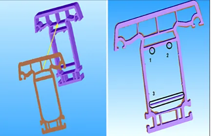
The element, whose shape we compare with the standard is scanned also in the first step, then the data are filtered and in the next step the ele-ments are fitted to each other (Fig. 10).
Elements fitting according to the Gaussian procedure are the basis for the plate surface shape assessment. The visualization of shape change is
possible, as in the case of a simple geometry ele -ment, in the form of a map. Values of deviations in certain points can be presented in a form of la -bels, in which are given points coordinates (x, y, z), components of shape deviation in given direc-tions and its value.
For compared elements obtained from mea -surements differences between shape of face planes in the area out of holes were up to 0.16 mm, which was the accuracy limit value of used measurement system. This allows to conclude that there are no significant differences in the ge-ometry of assessed complex shape elements.
Fig. 9. Element face plane model
Fig. 10. Reference model and a cloud representing the tested element – elements’ fitting
Fig. 11. Results of the element shape assessment by the comparison to the model
THE GEOMETRY ASSESSMENT OF MULTI
CELLS ELEMENT
As an example of an element with a complex geometry we may take the window profile which has a form of two to eight cells, which differ in wall thicknesses. Such a construction guarantees good thermal insulation, and therefore low heat transfer coefficient. Plastic profiles have also an excellent acoustic insulation. Since the PVC pro -files usually have low stiffness, the most suitable method to measure their geometry is to use opti -cal methods. The high complexity of the shape of concerned element makes it very difficult to measure it as a whole body, due to the lack of pos -sibility to map inner cell surfaces over the whole object length. Figure 12 shows the tested object and the effect of its digitization with visible fitting of the cylinder to one of the external open cells with the use of 3DReshaper software.
An alternative method for body measure -ments is performance of measure-ments and com -parisons in cross-section.
dis-tance measurements of selected points. A prelimi -nary assessment lets to note differences in shape (fragments marked with no. 1, 2, 3) and wall thicknesses of the measured element in relation to the model (3DReshaper).
To measure wall thicknesses for each cell GOM Inspect software was used. GOM Inspect software enables, among others, to:
• review and process 3D point clouds,
• 3D control and mesh process realization. The data processed in the system can be de -rived from white light scanners, laser scanners, computed tomography and coordinate machines.
Elements fitting in the front and side view re-alized in GOM system are shown in Figure 14.
Fig. 12. T window profile and the point cloud
repre-senting thereof
Fig. 13. Fitting of the section to the CAD model
Fig. 14. Elements fitting in GOM system
Measurement of cell wall thicknesses
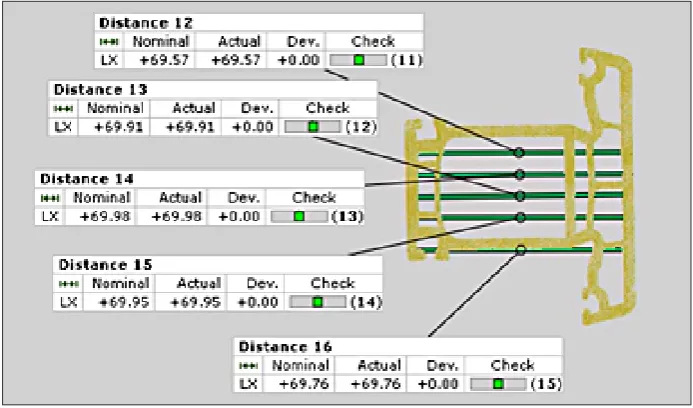
Measurements of wall thicknesses will be ref-erenced to the nominal geometry as shown in Fig -ure 15. Fig-ure 16 presents exemplary meas-ure -ments results and their visualization in relation to the external dimension of the profile.
In Figure 15 the nominal dimensions are marked with numbers 1–12. The obtained mea -surement results of certain characteristics are summarized in Table 1 and 2.
All the obtained wall thicknesses are larger than nominal values what results in greater rigid -ity of the profile.
CONCLUSION
The optical measurement method using laser scanner presented in the paper has proven to be an effective tool in measurements of objects of dif -ferent shape complexity. The presented examples have proven its high usefulness in both the assess -ment of conformity of a real ele-ment shape with nominal element and the assessment of objects deformation caused by wear and tear. The use of different programs to results assessment expands possibilities of the used measurement systems. Laser scanner in connection with an appropri -ate data processing system is a tool that enables measuring variable curvature elements, which are very difficult or impossible to be measured using conventional measurement systems.
REFERENCES
1. Gąska A., Olszewska M.: Porównanie różnych urządzeń metrologicznych wykorzystywanych w zastosowaniach biomedycznych, Postępy Nauki i Techniki, 06, 2011, 155-163.
2. Juras B., Sładek J., Szewczyk D.: Możliwość identyfikacji błędów kształtu przy wykorzysta-niu skanera optycznego, czasopismo Pomiary Au-tomatyka Kontrola, 01, 2012, 112-114.
3. Juras B., Szewczyk D.: Dokładność pomiarów re-alizowanych skanerem optycznym, Postępy Nauki i Techniki, 07, 2011, 29-36.
4. Ostrowska K., Szewczyk D., Sładek J.: Wzorcow-anie systemów optycznych zgodnie z normami ISO i zaleceniami VDI/VDE, Czasopismo Techniczne, 26, 2012, 167-179
5. Sitnik R. Karaszewski M.: Optimized point cloud
Fig. 15. Nominal dimensions of measured element: external dimensions and thicknesses of selected walls
Fig. 16. Height measurement with links
Table 1. Presentation of results of external dimensions measurements
Table 2. Presentation of results of wall thicknesses measurements
Element name
CAD value [mm]
Value point cloud [mm]
Average measurement 1 measurement 2 measurement 3 measurement 4 measurement 5
Base width 43 42.91 43.03 42.92 43.01 42.71 42.92
Peak width 85 84.71 84.76 84.79 84.66 84.72 84.73
Peak height 15.5 15.12 15.47 15.73 15.66 15.39 15.48
Profile height 70 69.89 69.91 69.98 69.95 69.76 69.90
Element number
CAD value [mm]
Value point cloud [mm]
Average
measurement 1 measurement 2 measurement 3 measurement 4 measurement 5
1 2.8 3.07 2.81 2.93 3.07 2.94 2.96
2 1.1 1.47 1.59 1.54 1.42 1.43 1.49
3 1.8 2.17 2.14 2.24 2.28 2.27 2.22
4 0.7 0.97 1.01 1.04 0.98 0.94 0.99
5 2.8 3.09 3.06 3.18 3.27 3.15 3.15
6 0.7 1 0.98 1.09 1 0.99 1.01
7 1.1 1.44 1.51 1.56 1.49 1.46 1.49
8 2.5 2.82 2.75 2.73 2.7 2.73 2.75
9 2.8 3.03 3.08 3.06 2.92 3.11 3.04
10 2.3 2.63 2.65 2.63 2.66 2.62 2.64
11 2.5 2.91 3.04 3.2 3.01 3.12 3.06
6. Sładek J., Gawlik J., Ryniewicz A., Krawczyk M., Ku-piec R.: Metrologia współrzędnościowa w inżynierii produkcji a dokładność pomiaru i dokładność wyt-warzania, Inżynieria Maszyn, 3, 2010, 20-34.
7. Sładek J., Gąska A., Olszewska M., Ostrowska K., Ryniewicz A.: Metoda oceny dokładności pomiarów realizowanych za pomocą ramion po-miarowych wyposażonych w optyczne głowice skanujące. Mechanik, 2, 2012, 133-139.
8. Sładek J., Ostrowska K., Gąska A., Gacek K., Kmita A.: Model matematyczny opisu dokładności Współrzędnościowych Ramion Pomiarowych.
Inżynieria Maszyn, 14(2), 2009. 7-18.
9. Sładek J., Ostrowska K., Gąska A.: Modeling and identification of errors of coordinate measuring arms with use of metrological model. Measure-ment, 46, 2013, 667-679.
10. Sładek J., Sokal G., Kmita A., Ostrowska K.: Wzorcowanie Współrzędnościowych Ramion Po-miarowych (WRP). Acta Mechanica et Automati-ca, 1(2), 2007.
11. Sładek J.: Dokładność pomiarów
współrzędnościo-wych. Wydawnictwo Politechniki Krakowskiej,