Evolution of the Software and Hardware in CAD/CAM
Systems used in Dentistry
1Rita Zarina, 2JL Jaini, 3Rajan S Raj MINI REVIEW
1Professor and Head, 2Reader, 3Assistant Professor
1Department of Pedodontics and Preventive Dentistry, Govt. Dental College, Kottayam, Kerala, India
2,3Department of Prosthodontics and Implantology, Amrita School of Dentistry, Kochi, Kerala, India
Corresponding Author: JL Jaini, Reader, Department of Prosthodontics and Implantology, Amrita School of Dentistry Kochi, Kerala, India, Phone: +919447461776, e-mail: drjainij@ gmail.com
ABSTRACT
The computer-aided design/computer-aided manufacturing (CAD/CAM) systems were introduced into dentistry in 1970s. This technology has evolved rapidly that, starting from a single crown to full mouth, rehabilitation is possible in a single day now. This article reviews the history, evolution, components, and various materials used for fabrication of prosthesis. It also evaluates popular CAD/CAM systems, its limitations, future evolvement, and also the dental considerations while using them.
Keywords: CAD/CAM systems, Cerec system, Digitalization tool, Evolution of CAD/CAM, Milling in CAD/CAM.
How to cite this article: Zarina R, Jaini JL, Raj RS. Evolution of the Software and Hardware in CAD/CAM Systems used in Dentistry, Int J Prev Clin Dent Res 2017;4(4):284-291.
Source of support: Nil
Conflict of interest: None
INTRODUCTION
Computer-aided design (CAD) and computer-aided man-ufacturing (CAM) have become an increasingly popular part of dentistry over the past 25 years.1 The CAD/CAM
technology was developed to solve three challenges. One of the challenges was to fabricate posterior restorations with sufficient strength. The second challenge was to create restorations with a natural appearance. The third challenge was to make restoration easier, faster, and more accurate.2 With recent versions of CAD/CAM systems it
is possible to make half-arch impressions in 40 seconds and full-arch impressions in just 2 minutes. The CAD/ CAM also makes designing and fabrication faster that a full-contour crown takes just 6 minutes to mill. Even by experienced technicians it takes multiple days to finish conventional restorations.3-5
HISTORy AND EvOLUTION Of DENTAL CAD/CAM SySTEMS
1970s saw rapid progress being made in computer-assisted processing technology in various industries and this was reflected in the field of dentistry also. Nickel-chromium alloys became a substitute for gold alloys in 1980s due to increase in the price of gold. But, metal aller-gies became a problem, especially in northern Europe, and a transition to allergy-free titanium was proposed. The precision casting of titanium was still difficult at that time.6 There was a strong requirement for an alternative
technique. Three pioneers in particular who contributed to the development of dental CAD/CAM systems are Duret, Moermann, and Anderson. Duret developed the Sopha® system, which had an impact on the later
develop-ment of dental CAD/CAM systems. He produced the first dental CAD/CAM restoration in 1983 and demonstrated his system at the French Dental Association’s Interna-tional Congress in November 1985 by creating a posterior crown restoration for his wife in less than an hour.5 Sopha
system was developed by Duret.3 Dr Moermann
devel-oped the CEREC® system, which was a chairside CAD/
CAM. The emergence of this system was very innovative because it allowed same day ceramic restorations. This was a turning point and it spread the term CAD/CAM.6
The third is Dr Andersson, the developer of the Procera®
system in 1983. Procera® system had central processing
center with satellite networking centers under this unit. Rekow7 used photographs and high-resolution scanners
to capture the data to mill restorations by a five-axis machine.6
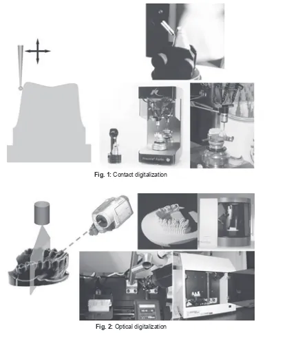
COMPONENTS Of CAD/CAM SySTEM Digitalization Tool/Scanner
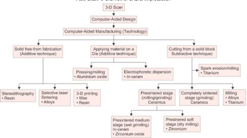
Geometrical data will be transformed into digital data by a digitalization tool to process in a computer. The digitizing accuracy is a major factor, which has an influ-ence on the fit of fixed restoration. Currently, the data acquisition is either performed directly in the patient’s mouth (intraoral) or indirectly after taking an impression and fabricating a master cast (extraoral). Triangulation is a procedure by which three-dimensional data will be collected by the computer.8 Digitalization can be contact
Evolution of the Software and Hardware in CAD/CAM Systems used in Dentistry IJPCDR
fine-tipped probe is used as the contact probe; even if it is very precise, it takes time to scan. The Procera Scanner from Nobel Biocare (Göteborg) is the only example for mechanical scanners in dentistry.6 This type of scanner is
distinguished by a high scanning accuracy, whereby the diameter of the ruby ball is set to the smallest grinder in the milling system, with the result that all data col-lected by the system can also be milled. The 3D scanners usually consist of a light source, one or more cameras, and a motion. The light source projects the light onto the surface of the object, and the camera(s) captures the images. Based on the known angle and distance between camera and light source (jointly called the scan head), the 3D position(s) where the projected light is reflected can be calculated using trigonometry. This is known as “triangulation.”9-12 Special software are provided by the
manufacturer to process the data for the design of various kinds of dental restorations. The software of CAD/ CAM systems presently available on the market is being continuously improved. The latest construction possibili-ties are continuously available to the user by means of updates. Even though the data for the construction can be stored in various data formats, it is often stored as standard transformation language data.13
Production Technology
Additive Technique by Applying Material on Die Alumina or zirconia is dry pressed on the die and the tem-perature is raised to a level, i.e., similar to the presintering state. Its outer surface is milled to the desired shape, the coping is removed from the die, and sintered in the furnace. Fig. 1: Contact digitalization
crowns and fixed partial dentures (FPDs) is to cut the contour out of an industrially prefabricated solid block of material.14
Milling in CAD/CAM
A production technology that transforms the set data into a desired product. Three-axis devices, four-axis devices, and five-axis devices enable the milling of complex geom-etries with subsections.13
Dry Processing
Dry processing is used with zirconium oxide blanks with a low degree of presintering and these results in higher shrinkage of the frameworks. Some manufacturers also offer the option of milling resin material in a dry milling process [Zeno 4030 (Wieland-Imes), Lava Form and Cercon brain].13
Wet Milling
A spray of cool liquid protects the milling diamond or carbide cutter against overheating of the milled mate-rial. This kind of processing is necessary for all metals and glass ceramic material in order to avoid damage through heat development. “Wet” processing is recom-mended, if zirconium oxide ceramic with a higher degree of presintering is employed for the milling process. Examples: Everest (KaVo), Zeno 8060 (Wieland-Imes), InLab (Sirona).13
Spark Erosion
Electric current under carefully controlled conditions is used for the metal removal process. It is used in fabrica-tion of fixed, removable, and implant prostheses.15
Three-dimensional Printing
It is another manufacturing approach to build objects, one layer at a time and adding multiple layers to form an object. It is also known as additive manufacturing or rapid prototyping (RP).16,17 It may be used for the fabrication of
metal structures either indirectly by printing in burn-out resins or waxes for a lost-wax process, or directly in metals or metal alloys like FPD and removable partial denture (RPD), polymerized prostheses, and silicon prosthesis.
Selective Laser Sintering
A scanning laser fuses a fine material powder, to build up structures layer by layer, as a powder bed drops down incrementally, and a new fine layer of material is evenly
the surrounding powder.
Stereolithography (SLA)
Light-sensitive polymer cured layer by layer by a scan-ning laser in a vat of liquid polymer. It is a widely employed RP technology. It was invented by Charles Hull. It is an additive manufacturing process in which a liquid photocurable resin acrylate material is used. Stereolithography uses a highly focused Ultraviolet (UV) laser to trace out successive cross-sections of a 3D object in a vat of liquid photosensitive polymer.21
Photojet
Light-sensitive polymer is jetted and cured layer by layer on an incrementally descending platform.
Digital Light Processing
Liquid resin is cured layer by layer by a projector light source. The object is built upside down with multiple increments.21
Powder Binder
Plaster or cementaceous material is set by drops from “inkjet” print head. Object will be built layer by layer in a powder bed.21
Fused Deposition Modeling
First 3D printing is most used in “home” printers. Ther-moplastic material extruded through nozzle onto built platform.22
CAD/CAM PRODUCTION: AN OvERvIEW
The CAM employs computer-generated paths to con-struct an object. A diverse set of technologies have been used to create dental restorations (Flow Chart 1).23
CLASSIfICATION Of DENTAL CAD/CAM SySTEMS
Based on production methods, CAD/CAM systems are divided as follows:
• In office systems: Most popular and accepted is Cerec system. It scans the tooth preparation intraorally and with this system the dentist can fabricate the restora-tions in the same appointment.24
Evolution of the Software and Hardware in CAD/CAM Systems used in Dentistry IJPCDR
technician to add esthetic porcelain for individualiza-tion and characterizaindividualiza-tion of the restoraindividualiza-tion.24
• CAD/CAM for outsourcing: “Satellite scanners” situated in the dental laboratory will be connected to a produc-tion center via the internet. Data sets produced in the dental laboratory are sent to the production center for the restorations to be produced with a CAD/CAM device. The benefit of outsourcing CAM production is found to be in the small investment requirement, since only the digitalization tool and software have to be purchased, still having access to a high-quality production process.24
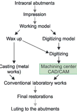
WORKfLOW Of DENTAL CAD/CAM SySTEMS
The workflow of the CAD/CAM systems can be sum-marized as below (Fig. 3).23
Evolution of CAD/CAM Systems
• First generation (Fig. 4)25: The final crown is fabricated
by milling a block using a numerically controlled machine.25
• Second generation (Fig. 5)25: Digitizers, such as contact
probe 8, laser beam with a position sensitive device sensor, and a laser with a charge-coupled device camera are used. Sophisticated CAD software and compact dental CAD/CAM machines were also developed. Consequently, both metallic and ceramic restorations were able to be fabricated by the second-generation CAD/CAM systems.25-34
• Third generation (Fig. 6)25: Since these high strength
industrial ceramics were not available to conventional dental laboratories, the application of networked Flow Chart 1: Overview of CAD/CAM production
CAD/CAM in a processing center was innovative in the history of dental technology. Such networked production systems are currently being introduced by a number of companies worldwide. Zirconia frame-works are now very popular in the world market. The framework is fabricated by CAD/CAM technology and final restorations are completed by veneering con-ventional porcelain used by dental technicians.25,34-37 • Fourth generation (Fig. 7)25: The application of dental
CAD/CAM systems is expected to shift to the fourth generation, as illustrated.24,35-37
MATERIALS USED fOR CAD/CAM SySTEMS
• Metals: At present, titanium, titanium alloys, and chrome cobalt alloys are processed using dental milling devices.13
• Resin materials: Resin materials can be directly used as crown and FPD frameworks as long-term provisional or long-term temporary prostheses. Example is Para-digm MZ100 (3M ESPE, St. Paul, Minnesota, USA).13 • Silica-based ceramics: Silica-based ceramic blocks are
offered by several CAD/CAM systems for the fabrica-tion of inlays, onlays, veneers, partial crowns, and full
crowns. Lithium disilicate ceramic blocks are highly stable. Glass ceramics are good for chairside applica-tion because of their translucent characteristics.13,38-41 • Infiltrated ceramics: Infiltration ceramics are manufac-tured in a porous, chalky condition and then infil-trated with lanthanum glass. All blanks for infiltration ceramics originate from the Vita In-Ceram system (Vita) and are offered in three variations:
– Vita In-Ceram Alumina (Al2O3): Suitable for crown copings in the anterior and posterior region; three-unit FPD frameworks in the anterior region.42,43
– Vita In-Ceram Zirconia (70% Al2O3, 30% ZrO2): Suitable for crown copings in the anterior and posterior region, three-unit FPD frameworks in the anterior and posterior region. This ceramic is suitable for discolored abutment teeth.42,43
– VITA In-Ceram Spinell (MgAl2O4): Has the highest translucency of all oxide ceramics and is thus recommended for the production of highly esthetic anterior crown copings, in particular on vital abutment teeth and in the case of young patients.42,43
• Aluminum Oxide (Al2O3): This high-quality ceramic is ground initially and then sintered at a temperature of 1520°C. They are used for fabrication of copings, crowns in the anterior and posterior regions. It is also used for three-unit anterior FPD frameworks.13 • Yttrium stabilized zirconium oxide (ZrO2, Y-TZP):
Zirconium dioxide is a high-performance oxide ceramic with excellent mechanical characteristics. Its high flexural strength and fracture toughness com-pared with other dental ceramics offers the possibility of using this material as framework for crowns and FPDs, and, as an appropriate indication, for individual implant abutments.13
Fig. 5: Second-generation CAD/CAM systems workflow
Fig. 6: Third-generation CAD/CAM systems workflow
Evolution of the Software and Hardware in CAD/CAM Systems used in Dentistry IJPCDR
POPULAR SySTEMS Cerec System
This was introduced in 1987. It comes with digital scan-ning with a milling unit. The system enables dentists to cement restorations in a single visit. The earliest models produced inlays and onlays only, but the newest model, known as CEREC AC has the ability to take half-arch or full-arch impressions and create crowns, veneers, and bridges.44,45
The E4D Dentist System
This was introduced in 2008. This is another system which permits cementation of restorations in the same visit. It comprises a laser scanner, called IntraOral Digitizer, a design center, and milling unit. As the scanner is small, patients do not need to open the mouth wide. The E4D system requires the use of powder in some but not in all cases. The office milling machine will then manufacture the restoration from the chosen blocks of ceramic or composite.2,46
Cadent Introduced iTero
In 2007, it was developed as the first digital impression system for conventionally manufactured crowns and bridges. In order to capture the data, iTero employs paral-lel confocal imaging. The device projects red laser light and captures the reflected light to transform into digital data. This technology allows scans to be taken without coating the teeth in powder.46-48
The Lava
This was introduced in 2008. The system includes a mobile cart, a touch screen display, and a scanner with a camera at the end. The camera consists of light-emitting diodes (LEDs) and lens systems. It uses active wavefront sampling to capture images. After signing off on the scans, the data are sent through wireless to the laboratory, where the die is cut and the margin marked digitally.
Procera All Ceram System
It was launched in 1994. It is based upon an outsourced fabrication using a network connection. The master die is scanned and data sent to processing center. After fabrica-tion, the coping will be sent back to the lab for porcelain veneering.6,24
DCS Precident
Comprises a Preciscan laser scanner and Precimill CAM multitool milling center. It can scan 14 dies simultane-ously and mill up to 30 framework units in one fully
automated operation. It can mill titanium as well as fully dense sintered zirconia.6,24,25
CICERO System
It incorporates optical scanning, sintering, and milling. Basic reconstruction includes layered life like ceramic for natural esthetics, a precision milled occlusal surface, and a machined high strength ceramic core. The aim of CICERO is to mass produce ceramic restoration at one integrated site.6,24,25
Cercon
It is used for the fabrication of zirconia-based prostheses. Impression of the abutment teeth is made and sent to the laboratory, to make a model. A wax pattern is made for each coping or the crown areas of the framework of a FPD. The pattern is scanned and the blank is rough-milled and fine-milled on occlusal and gingival aspects in an enlarged size to compensate for the 20% shrinkage.6,24,25
CELAy System
This is developed by Dr Stefan I. Eidenberg at the Uni-versity of Zurich. The model of restoration is fabricated using a resin on the master model. This is fixed in an attachment unit and is copied by means of mechani-cal sensoring. Following this, restoration is milled. The degree of freedom and the interpretation of the CELAY system’s reader allows it to shape any forms from indus-trially presintered ceramic blocks.6,24,25
DENTAL CONSIDERATIONS
Even though the CAD/CAM systems possess lot of advantages, the dentist’s working procedures will have to be adapted to the methods of CAD/CAM and milling technology. These include appropriate tooth preparations with the creation of a continuous preparation margin, which is clearly recognizable to the scanner. Based on the present knowledge, a tapered angle of between 4 and 10° is recommended. Subsections and irregularities on the surface of the prepared tooth as well as the “creation of troughs” with a reverse bevel preparation margin can be inadequately recognized by many scanners. In addition, sharp incisor and occlusal edges are to be rounded. Sharp edges cannot be milled exactly using rounded grinders in the milling device.13
fUTURE TECHNOLOGIES
come down.
LIMITATIONS Of CAD/CAM
The powder layer applied to the tooth surface results in an additional thickness of 13 to 85 μm. The restricted mea-suring conditions in the mouth, including the presence of adjacent teeth, gingiva, and saliva, make accurate recogni-tion of the margin of an abutment difficult. Regardless of the digitizing mode applied, clinical parameters, such as saliva, blood, or movements of the patient can affect the accurate reproduction of teeth. This has been a critical limitation of the system to fabricate final precision resto-rations. The CAD/CAM milling procedures may induce surface and subsurface flaws that may adversely affect the strength of this ceramic. Enhancement of strength (to approximately 160 MPa) can be acquired by a combina-tion of polishing and glazing.2,13
CONCLUSION
As Duret stated, “The systems will continue to improve in versatility, accuracy, and cost effectiveness and will be a part of routine dental practice in coming time”. Incorporation of these systems into dental practice is yet limited. Dentists should get training and access to these systems, technologies, and developments. We must combine new and conventional technologies to meet the patient demands.
REfERENCES
1. Duret F, Blouin JL, Duret B. CAD-CAM in dentistry. J Am Dent Assoc 1988 Nov;117(6):715-720.
2. Davidowitz G, Kotick PG. The use of CAD/CAM in dentistry. Dent Clin North Am 2011 Jul;55(3):559-570.
3. Mormann WH, Brandestini M, Lutz F, Barbakow F. Chairside computer-aided direct ceramic inlays. Quintessence Int 1989 May;20(5):329-339.
4. CEREC AC. The CEREC Acquisition Center powered by Bluecam. Charlotte (NC): Sirona; 2008. [cited 2010 Aug 6]. Avail-able from: http://www.cereconlin.com/cerec/acquisition- center.html.
5. CEREC AC. CAD/CAM for everyone [pamphlet]. Charlotte (NC): Sirona.
6. Takashi M, Yasuhiro H, Jun K, Soichi K. A review of dental CAD/CAM: current status and future perspectives from 20 years of experience. Dent Mater J 2009 Jan;28(1):44-56. 7. Rekow ED. Dental CAD-CAM systems. What is the state of
the art? J Am Dent Assoc 1991 Dec;122(12):42-48.
8. Miyazaki T, Hotta Y, Kunii J, Kuriyama S, Tamaki Y. A review of dental CAD/CAM: current status and future perspectives from 20 years of experience. Dent Mater J 2009 Jan;28(1):44-56. 9. Persson M, Andersson M, Bergman B. The accuracy of a high-precision digitizer for CAD/CAM crowns. J Prosthet Dent 1995 Sep;74(3):223-229.
Univ Dent Soc 1999;19(2):158-162
11. Kobayashi Y, Lee G, Hotta Y, Fujiwara N, Miyazaki T. The effect of proximal teeth on the digitizing accuracy of the shoulder margin of the crown abutment by a laser digitizer equipped in an experimentally developed CAD/CAM device. J Showa Univ Dent Soc 2000;20(1):158-164.
12. Hollenbeck K, Allin T, van der Poel M. Dental lab 3D scanners – how they work and what works best. Copenhagen: 3Shape Technology Research; 2012. p. 1-5.
13. Beuer F, Schweiger J, Edelhoff D. Digital dentistry: an over-view of recent developments for CAD/CAM generated restorations. Br Dent J 2008 May;204(9):505-511.
14. Prajapati A, Prajapati A, Mody DR, Choudhary AB. Dentistry goes digital: a CAD-CAM way – a review article. IOSR J Dent Med Sci 2014 Aug;13(8):53-59.
15. Jo LJ. Spark erosion process: an overview. J Dent Implants 2011 Jan-Jun;1(1):2-6.
16. Andonović V, Vrtanoski G. Growing rapid prototyping as a technology in dental medicine. Mech Eng Sci J 2010;29(1):31-39. 17. Liu Q, Leu MC, Schmitt SM. Rapid prototyping in dentistry:
technology and application. Int J Adv Manuf Technol 2006 Jun;29(3):317-335.
18. Deckard, CR. Method and apparatus for producing parts by selective sintering. US Patent 4863538 A. Filed 17 Oct 1986. 1989.
19. Deckard C, Beaman JJ. Process and control issues in selective laser sintering. ASME Prod Eng Div PED 1988 Nov-Dec;33: 191-197.
20. Kruth, JP.; Vandenbroucke, B.; Van Vaerenbergh, J.; Mercelis, P. Benchmarking of different SLS/SLM processes as rapid manufacturing techniques. Proceedings of 1st International Conference of Polymers and Moulds Innovations, Gent, Belgium. April 20-23. 2005. p. 1-7.
21. Dawood A, Marti Marti B, Sauret-Jackson V, Darwood A. 3D printing in dentistry. Br Dent J 2015 Dec;219(11):521-529. 22. Torabi K, Farjood E, Hamedani S. Rapid prototyping
tech-nologies and their applications in prosthodontics, a review of literature. J Dent Shiraz Univ Med Sci 2015 Mar;16(1):1-9. 23. Strub JR, Rekow ED, Witkowski S. Computer-aided design
and fabrication of dental restorations current systems and future possibilities. J AM Dent Assoc 2006 Sep;137(9): 1289-1296.
24. Mantri SS, Bhasin AS. CAD/CAM in dental restorations: an overview. Ann Essences Dent 2010 Jul-Sep;2(3):123-128. 25. Miyazaki T, Hotta Y. CAD/CAM systems available for the
fabrication of crown and bridge restorations. Aust Dent J 2011 Jun;56(Suppl 1):97-106.
26. Hotta Y. Fabrication of titanium copings using the CAD/CAM process. Japan J Dent Mater Dev 1992;11:169-178.
27. Hotta Y, Miyazaki T, Lee G, Kobayashi Y. Accuracy of the ceramic crown fabricated by the newly developed CAD/ CAM system. J Showa Univ Dent Soc 1996;16:230-234. 28. Hotta Y, Miyazaki T, Warita K, Kawawa T. Automatic
fabrica-tion of ceramic crowns using a newly developed dental CAD/ CAM system. J Esthet Dent 1998;10:69-75.
Evolution of the Software and Hardware in CAD/CAM Systems used in Dentistry IJPCDR
30. Miyazaki T, Hotta Y, Kobayashi Y, Lee G, Furuya A, Kawawa T. Characteristics of dental CAD⁄CAM system “Decsy” and clinical application. QDT 2000;25:34-41.
31. Hotta Y, Ozawa A, Kobayashi Y, Miyazaki T. Development of a dental CAD/CAM system fabricating dental prostheses. J Showa Univ Dent Soc 2001;21:86-91.
32. Hotta Y, Miyazaki T, Fujiwara T, Tomita S, Shinya A, Sugai Y, Ogura H. Durability of tungsten carbide burs for the fabrica-tion of titanium crowns using dental CAD/CAM. Dent Mater 2004 Jun;23(2):190-196.
33. Tomita S, Shinya A, Gomi H, Matsuda T, Katagiri S, Shinya A, Suzuki H, Yara A, Ogura H, Hotta Y, et al. Machining accu-racy of CAD/CAM ceramic crowns fabricated with repeated machining using the same diamond bur. Dent Mater 2005 Mar;24(1):123-133.
34. Suttor D, Bunke K, Hoescheler S, Hauptmann H, Hertlein G. LAVA – the system for all-ceramic ZrO2 crowns and bridge frameworks. Int J Comput Dent 2001;4:195-206.
35. Sorensen JA. The Lava system for CAD/CAM production of high-strength precision fixed prosthodontics. QDT 2003;26: 57-67.
36. Piwowarczyk A, Ottl P, Lauer H-C, Kuretzky T. A clinical report and overview of scientific studies and clinical pro-cedures conducted on the 3M ESPE LavaTM. J Prosthodont 2005;14:39-45.
37. iTero. 2010. [cited May 2010]. Available from: http://www. cadentinc.com.
38. 3M ESPE. 2010. [cited May 2010]. Available from: http:// solutions.3m.com/wps/portal/3M/en_US/LavaCOS/ 3MESPE-LavaCOS/.
39. Sirona. 2010. [cited May 2010]. Available from: http://www. cereconline.com/cerec/.
40. D4D Technologies LLC. 2010. [cited May 2010]. Available from: http://www.e4d.com/.
41. Sorensen JA, Choi C, Fanuscu MI, Mito WT. IPS Empress crown system: three-year clinical trial results. J Calif Dent Assoc 1998 Feb;26(2):130-136.
42. Sorensen JA, Cruz M, Mito WT, Raffeiner O, Meredith HR, Foser HP. A clinical investigation on three-unit fixed partial dentures fabricated with a lithium disilicate glass ceramic. Pract Periodontics Aesthet Dent 1999 Jan-Feb;11(1):95-106. 43. Taskonak B, Sertgöz A. Two-year clinical evaluation of
lithium-disilicate based all-ceramic crowns and fixed partial dentures. Dent Mater 2006 Nov;22(11):1008-1013.
44. Tinschert J, Natt G, Mautsch W, Augthun M, Spiekermann H. Fracture resistance of lithium disilicate-, alumina-, and zirconia-based three-unit fixed partial dentures: a laboratory study. Int J Prosthodont 2001 May-Jun;14(3):231-238. 45. Raigrodski AJ, Chiche GJ. All-ceramic fixed partial dentures,
Part I: in vitro studies. J Esthet Restor Dent 2002 May;14(3): 188-191.
46. Raigrodski AJ, Chiche GJ, Swift EJ Jr. All-ceramic fixed partial dentures, Part III: clinical studies. J Esthet Restor Dent 2002 Sep;14(5):313-319.
47. Andersson M, Carlsson L, Persson M, Bergman B. Accuracy of machine milling and spark erosion with a CAD/CAM system. J Prosthet Dent 1996 Aug;76(2):187-193.