Shortest Path Based Dynamic Route Adjustment Scheme for Data
Collection in a Wireless Sensor Network with a Multiple Mobile Sink
Sanjana B.M1, Vikas C. Yatnalli2
1 (Electronics and Communication, VTU, and Davanagere) 2 (Electronics and Communication, VTU, and Davanagere)
---
******************
---Abstract:
The load balancing is one of the major constraints in the wireless sensor network. Single mobile sink give rise to the collision, the packet loss and communication delay. Thus usage of two mobile sink based approach is proposed. Identifying the sink location and routing path is the most challenging task in a wireless sensor network. In this scheme based upon the number of nodes, the nodes are divided into clusters, by the common node id and coordinate values the cluster heads will communicate to their respective mobile sink with the shortest routing algorithm. Update information of the sink to every cluster head leads to abundant energy usage and decrease the lifetime of the network, which is overcome in this approach. Proposed method performance is compared with the current approach named EECLA .Simulation results show that there is a vast improvement in the lifetime of the wireless sensor network when compared with the existing scheme.
Keywords
—
Wireless sensor network, mobile sink, cluster head, energy hole.---
******************
---I. INTRODUCTION
A wireless sensor network comprises of a large number of sensor nodes, which are deployed within an application area to monitor a specific event usually where human intervention is not possible. Since the sensor nodes are operated by a battery source, the energy consumption of the battery should be less in order to prolong the network lifetime of the wireless sensor network. The sensor nodes co-operatively work together for the specific event and report the collected data to a central base station or a sink. In a wireless sensor network with a sink remain static the nodes nearer to a sink will gets the heavy traffic load which may deplete its energy much faster when compared to the other nodes. As a result of the death of the nodes nearer to sink takes place which leads to network partition. This is called energy hole problem or also called as the hot stop problem. Moreover the sink could become isolated and the data from the sensor nodes across the network would no longer be obtained. Therefore, the load balancing must be in corporate in order to achieve the uniform energy consumption across the network. So the usage of mobile sink based approach is proposed. The mobile sink not only provides the load balancing, but can also link the isolated network segments in an application area. Sink mobility helps to achieve the uniform energy consumption and improves the network lifetime of the wireless sensor network.
Several application environments, requires sink mobility in the sensor field e.g: the forest fire detection system, which consists of numbers of sensor nodes situated in a forest area and one or multiple mobile sink. In case of fire detection, there will be a drastic change in the sensor values of the sensor nodes, where by their reporting
frequency increases. The mobile sink could be placed on a motorized vehicle or carried by the human. The sink could be moved across the forest for the periodic data collection from the various sensor nodes. The mobile sink would assist for the extinguishing of the forest fire by providing the fresh and detailed information of the area of interest.
Other applications of the mobile sink include battle field surveillance, where the sensors detect the enemy group or the movement of vehicles. In the battle field the static sink are not preferred because they are easily located and compromised by the attackers. Disaster management, pollution control, traffic monitoring and rescue missions are the other example scenarios.
moved in a anticlockwise direction to collect the data from the cluster head in a single hop manner. The cluster heads located near the border of the sensing field are responsible for the tracking of the latest location of the mobile sink. Based upon the shortest routing path the inter cluster communication with the cluster head with respect to the particular mobile sink occurs. In the SPDRA scheme the optimal routes are required for the communication between the cluster head and the mobile sink. Simulation results reveal that there is improvement in the lifetime of the wireless sensor network when compared with the existing one.
II. LITERATURE SURVEY
.
Wendi Rabiner Heinzelman [1] proposed a leach protocol where the cluster head selection is random and changes every time. Since the cluster head is random there is a possibility of two or more cluster heads are very close to each other where the significant energy loss occurs and throughput is also reduced.
Can Tunca [2] proposed distributed mobile sink routing for the wireless sensor network, where the sink will collect the data when it passes along the communication range of the sensor nodes. In this method the nodes need not be always active. The main disadvantage of this method is the data delivery is not guaranteed one and there is a larger delay in wait for the sink to disseminate the data.
Richard Silva [3] proposed mobility in wireless sensor network where the mobile sink will determines the cluster head in the particular area and gets the data from only that particular cluster head. The main disadvantage of this method is it can be only used in delay tolerant application and the aggregated data from the cluster head could be collected by the mobile sink when it comes closer to the cluster heads. But this protocol does not guarantee that the sink that the sink will visit all the cluster head within the specified amount of time.
Neha Upadhyay and Vikram Jain [4] proposed a hierarchical and cluster based routing protocol which supports node and sink mobility. This protocol consists of two phases namely setup and data forwarding with three different types of nodes called gateway.
Ming Chen [5] proposed an energy efficient routing protocol with a mobile sink based on the shortest path data transmission mode. By comparing the coordinate value of each sensor node and common nodes id shortest path is found to forward the nodes data to sink. In this method the shortest path calculated between the sensor nodes itself to reach the sink requires more number of hops.
Abdul Waheed Khan [6] proposed a scheme called Virtual grid based dynamic route adjustment scheme to minimize the route reconstruction cost where only the limited number of nodes readjust there data delivery to reach the latest location of mobile sink. The main disadvantage of this scheme is by the usage of single mobile sink collision, packet loss, time delay due to obstacles, coverage area, link failure and more retransmission of data packets occurs between the cluster heads.
T.Nagamalar and T.R Rangaswamy [7] proposed the scheme called Energy efficient cluster based algorithm for data collection in wireless sensor network where the sensor field is exactly divided into two equal halves and the mobile sinks are allowed to move in a anticlockwise direction for every half of the round. The main disadvantage of this method is the cluster head belonging to the first half round should communicate only to the respective mobile sink where the number of hops required to reach the sink increases. So the network lifetime gets reduced in this approach. Therefore the SPDRA scheme is proposed to improve the network lifetime when compared to EECLA scheme.
III.DESIGNANDIMPLEMENTATION
.
This section provides the complete description of the SPDRA scheme. In this scheme the sensor field is partitioned into equivalent sized cells and the clusters totally formed are a function of number of nodes present in the network. Nodes having a higher residual energy and close to the midpoint of cell are appointed as CH’s, where the cluster head duty is to know the location of mobile sink which relives the burden of the cluster members to take part in route change as the mobile sink is moved every time. The nodes other than cluster heads connect with the cluster head comes under its communication range and communicate in a single hop manner. Task of cluster members is to sense the information and send it to cluter head , then CH collects the nodes data and further transmit to the sink via the inter cluster communication.
A. Network characteristics
The below furnished assumptions are made before dealing with the methodology of the SPDRA scheme the
1) Nodes are assumed to be static in the sensor field and deployed in random.
2) All the sensor nodes having their initial energy of 0.5 J and are homogeneous in nature.
3) The two mobile sinks don’t have any resource constraints and are highly powered.
4) The distance required by every sensor node to reach the destination node determines the transmission power
5) The two mobile sink performs the data collection in a regular period from the CH by moving along the periphery of the application field
B. SPDRA Structure Construction
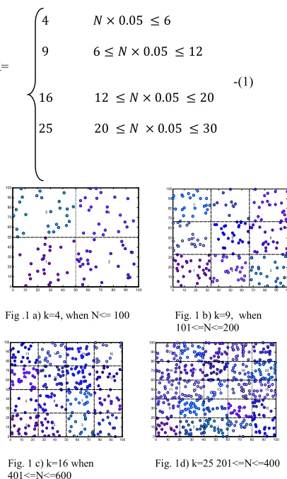
The SPDRA scheme forms the structure by uniformly dividing the nodes into equal sized cluster based upon the total number of nodes in the network. The reason behind the division of clusters is to distribute the load uniformly and to improve the lifetime of the network.
percent. Figure 1 shows the partitioning of the network into uniformly sized cells where N= 100, 200, 300 and so on.
4 0.05 6
9 6 0.05 12
K=
-(1)
16 12 0.05 20
25 20 0.05 30
Fig .1 a) k=4, when N<= 100 Fig. 1 b) k=9, when 101<=N<=200
Fig. 1 c) k=16 when Fig. 1d) k=25 201<=N<=400 401<=N<=600
Fig. 1 Example of different SPDRA network structures for varying number of nodes
C. Dynamic Routes Adjustment
Since the sink is moving in this approach the nodes need to dynamically readjust their route based upon the sink mobility. Only the limited number of cluster heads is involved in the route adjustment in this approach. After knowing the location of the sink, the cluster heads present in the border will informs to the other cluster members in a controlled manner.
The propagation rules required for the route adjustment in the SPDRA scheme are as follows.
Rule 1: The two mobile sink will start to move from the initial position which is predetermined. The nearest cell header w.r.t to the two mobile sink, finds the location of mobile sinks and informs to the remaining cell headers. In this way the initial route set up takes place.
Rule 2: The originating cell header will obey and follow rule 3 if the next consecutive hop is a mobile sink, or else it will continue to work as per the rules of ‘shortest path algorithm’
Rule 3: Mobile sink is set as next hop if the mobile sink is the very next hop to origination cell header. And the same
information is shared with the child node and prior originating cell header.
Rule 4: The current originating cell header will send the information of the sink location to the previous originating cell header which enables it to manipulate its route by
setting its next hop as current originating cell header.
Rule 5: Child node after receiving the mobile sinks updated position checks whether the update information has come from the sender cell header has previously set as next hop. If it is previously set as next hop, then no route updation is required. The child nodes should always want to check whether the new nodes are added to the network of the respective mobile sink, if any nodes are added then the route set-up takes place according to DIJKSTRA based shortest routing algorithm.
Both the mobile sink 1 and mobile sink 2 should follow the above rules for every round.
Fig. 2 Example of route adjustment during initial setup.
Fig. 3 Example of route readjustment when the mobile sink1 moves from cell 1 to cell2 and mobile sink2 moves from cell 16 to cell15
0 10 20 30 40 50 60 70 80 90 100 0 10 20 30 40 50 60 70 80 90 100 1 3 2 4
0 10 20 30 40 50 60 70 80 90 100 0 10 20 30 40 50 60 70 80 90 100 1 4 7 2 5 8 3 6 9
0 10 20 30 40 50 60 70 80 90 100 0 10 20 30 40 50 60 70 80 90 100 1 5 9 13 2 6 10 14 3 7 11 15 4 8 12 16
Fig. 4 Example of route readjustment when mobile sink1 moves from cell 2 to cell 3 and mobile sink2 moves from cell 15 to cell 14
D. Cluster Head Rotation
The most important part in the SPDRA method is the rotation of CH. The CH’s are always more susceptible to higher energy dissipation and the role of CH is to be distributed so that we can improve periodicity of the sensor network.
To achieve the uniform energy distribution the SPDRA scheme always tracks the residual energy of the current cluster head. If the residual energy of the present cluster head falls below the minimum threshold value, then the fresh cluster head is formed for the current cluster. Otherwise the same cluster head will remain as the cluster head for its cluster until its energy lies below the threshold limit.
Current CH before stepping down from its position will share the information not only to the current cell header but to the member nodes of the cluster and also to the adjacent neighbouring cell headers.
Due to the avoiding of the frequent cluster head formation and formation of new cluster every time. There is a vast improvement in the energy consumption in this scheme. Also the usage of two mobile sinks avoids the collision, packet loss and the retransmission of the packets.
IV. SIMULATION RESULTS
The simulation results are presented using the mat lab tool. Sensor nodes are positioned erratically in a sensor field of 100 ×100 dimension. The two mobile sink are moved in the anticlockwise direction and broadcasts the hello message.
The transmission energy required to transmits m bit packets at a distance d is given by,
ETx(m, d) = mE + md∝= mE + mE d
-(2)
E is the energy required for amplification which rely
on the distance to be transmitted and bit error rate.
E is the energy required for the transmission/bit.
E is the energy required for processing.
ERx(m) = mE + E − (3)
Total Energy Consumed (E ) = ET + ER + E + E + E − (4) Where,
ETx(m, d)– Energy required by the packets of ‘m’ bits for transmission
ERx(m) − Energy required by the packets of ‘m’ bits for reception.
E – Energy used by the radio unit
E + E + E - Energy used in sensing, sleep
and idle state
Total Energy used (Econs) = ETx+ ERx+ Eradio
The total energy in the network at the start up
E = N(ϒE +¥E ) − (5)
Where,
N- Number of nodes in a network.
ϒ – Percentage of nodes ¥ - Percentage of cluster heads.
E – Energy of normal nodes.
E – Energy of cluster head.
Residual Energy = E − E − (6)
Simulation parameters:
TABLEI
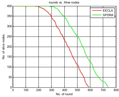
A. Number of alive nodes v/s Number of rounds
Fig. 5 Number of alive nodes versus Number of round
0 100 200 300 400 500 600 700 800
0 50 100 150 200 250 300 350 400
No. of round
No
. o
f a
liv
e
no
de
s
rounds vs. Alive nodes
EECLA SPDRA
Parameters Values
Header Size 25 bytes
Data Size 500 bytes
Carrier Frequency 914MHz
Path loss coefficient (γ) 2
CSThresh 1nw
RXThresh 6nw
Number of Nodes 400
Excvr (Energy for radio circuitry) 50nJ
Eamp (Energy for amplification) 0.659 nJ/m2
Ecpu (Energy for processing) 7nJ/bit
Eelec (Energy required for transmission/bit) 50nJ/bit
Simulation Area 100*100m
Simulation
Figure 5 demonstrates the number of alive nodes versus the number of rounds taken in a network for its completion or till the last node death. The number of alive nodes in the SPDRA scheme is quite better than the number of alive_nodes occurs in the existing scheme called EECLA.
B. Variance v/s Number of round
Fig. 6 Variance v/s Number of round
Figure 6 shows the variance versus number of rounds. Simulation results demonstrate that the variance is less in the projected method when compared with the EECLA scheme as the number of rounds increases. Variance indicates the nonuniform energy consumption that exists between the nodes. Variance should be less for the better network lifetime.
C. Residual energy v/s Number of Round
Fig. 7 Residual energy versus number of round
Figure 7 shows residual energy versus the number of rounds. Residual energy indicates the residual energy that exists in the node after the transmission and reception of the data packets in the network with respect to the number of rounds. The residual energy of the nodes is more in the projected method when compared to the existing scheme w.r.t number of rounds.
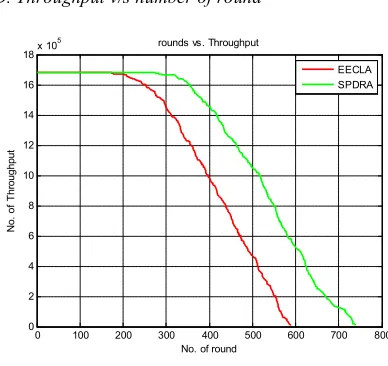
D. Throughput v/s number of round
Fig. 8 Throughput versus number of rounds
Figure 8 represents throughput versus the number of rounds which indicates the successful delivery of packets by the nodes over a communication channel .Simulation results demonstrates there is an increase in the throughput in the proposed method when compared to that of the existing scheme.
V.
CONCLUSIONWith the usage of two mobile sink load balancing is achieved without any extra effort which leads to increase in the network period of existence. CH is elected in the particular cluster on the basis of highest residual energy and the node nearer to a centre. Sensor nodes communicate with its cluster head in a single hop and the inter cluster communication takes place through the shortest routing path. Finally the closer CH is responsible for the collection of data from the remaining CH and transfers its data to sink. Performance of the network is considered based upon alive nodes probabablity, residual energy, variance and throughput compared with the existing scheme. There is a vast improvement in the performance of the network when correlated with the EECLA scheme. Finally the SPDRA scheme helps to extend the network lifetime of the wireless sensor network.
ACKNOWLEDGMENT
I express my sincere thanks to Vikas C. Yatnalli Department of Electronics and Communication, G.M Institute of Technology, Davanagere, Karnataka for the consistent support and encouragement for the successful completion of this paper.
0 100 200 300 400 500 600 700 800 0
0.005 0.01 0.015 0.02 0.025
No. of round
Va
ria
nc
e
rounds vs. Variance
EECLA SPDRA
0 100 200 300 400 500 600 700 800
0 20 40 60 80 100 120 140 160 180 200
No. of round
Re
si
du
al
e
ne
rg
y
rounds vs. residual energy
EECLA SPDRA
0 100 200 300 400 500 600 700 800
0 2 4 6 8 10 12 14 16 18x 10
5
No. of round
No
. o
f T
hr
ou
gh
pu
t
rounds vs. Throughput
REFERENCES
[1] Wendi Rabiner Heinzelman, Anantha Chandrakasan and Hari Balakrishnan, “Energy Efficient Communication Protocol for Wireless Microsensor Networks”, Hawali International, January 2000.
[2] Can Tunca, Sinan Isik, M. Yunus Donmez, Cem Ersoy, “Distributed
Mobile Sink Routing for Wireless Sensor Networks: A Survey”, pp.1- 21
[3] Ricardo Silva, Jorge Sa Silva, Fernando Boavida, “Mobility in wireless sensor networks –Survey and proposal”, Elsevier, Computer Communications, pp. 1-20, 2014.
[4] Neha Upadhyay and Vikram Jain, “Node and Sink moility supported routing protocol in wireless sensor network with improved energy efficiency”, International Journal of Computer Science and Mobile Computing, Vol.2, Issue 6, pp. 267-273 June 2013.
[5] Ming Chen, Xumin Xu, Shaohui Zhang, Guofu Feng, “Energy
Efficient Routing Protocl in Mobile Sink wireless sensor networks”, TELKOMNIKA, Vol.10, No.8, pp. 2056-2062, December 2012
[6] Abdul Waheed Khan, Abdul Hanan Abdullah, Mohammad Abdur
Razzaque and Javed Iqbal bangash, “VGDRA : A virtual Grid based Dynamic Routes adjustment Scheme for Mobile Sink based Wireless Sensor Networks”, IEEE Sensors Journal, Vol.0. No. 0, pp. 1-9, January 2014
[7] T.Nagamalar and T.R Rangaswamy, “energy Efficient Cluster Based Approach for Data Collection in a Wireless Sensor Network With Multiple Mobile Sink- International conference on Industrial Instrumentation and control -May 2015.