Development and evaluation of a low-cost precision seeding control system
for a corn drill
Xiang Yin
1,
Noboru Noguchi
2,
Tengxiang Yang
3,
Chengqian Jin
1,3*(1. School of Agricultural Engineering and Food Science, Shandong University of Technology, Zibo 255000, China; 2. Research Faculty of Agriculture, Hokkaido University, Kita 9 Nishi 9, Kita-ku, Sapporo 060-8589, Japan;
3. Nanjing Research Institute for Agricultural Mechanization of Ministry of Agriculture and Rural Affairs, Nanjing 210014, China)
Abstract: Precision seeding requires that the corn drill drop seeds into the soil by a specific in-row spacing while its travelling
speed fluctuates due to unevenness of the field ground. This paper presents a low-cost precision seeding control system for a conventional corn drill with mechanical metering devices of finger-pickup type. A median filtering method was implemented in the control system to process measurements from a rotary encoder in order to acquire stable values of the corn drill travelling speed. The metering unit was driven by an electric motor controlled by the metering ECU according to the actual travelling speed and the desired in-row spacing in real-time. A user interface was programmed to communicate with ECUs for configuring parameters and displaying operating information during working. The newly-developed precision seeding control system was first calibrated in terms of speed measurement and control for two ECUs. Experiments were conducted on a seeding test platform in the laboratory for evaluating its accuracy in dropping seeds by giving different in-row spacing under different travelling speeds of the conveyor sticky belt. Results showed that the average spacing error was less than 2 cm and the maximum RMS error was 0.78 cm for all spacing values including 25 cm, 30 cm and 35 cm under the travelling speed of 1.0-8.0 km/h. These indicated that the low-cost precision seeding control system worked in a both accurate and stable way.
Keywords: precision seeding, corn drill, control system, travelling speed, in-row spacing DOI: 10.25165/j.ijabe.20181105.3369
Citation: Yin X, Noguchi N, Yang T X, Jin C Q. Development and evaluation of a low-cost precision seeding control system
for a corn drill. Int J Agric & Biol Eng, 2018; 11(5): 95–99.
1 Introduction
With the development of precision farming in smart agriculture, variable rate application (VRA) has been becoming increasingly popular, which is intended to make full use of investment of seeds, fertilizers and pesticides according to site-specific management principles within one field. The performance of an active optical sensor for variable N rate fertilization was evaluated to minimize N surplus in areas of lower productivity and to improve the sustainability of N management overall[1]. An on-the-go visible and near infrared soil sensor was used to optimize the prescription map for VRA of the elemental P[2]. Environmental benefits of variable rate N fertilizer and cost was demonstrated by presenting experimental results of applying two N rates in each of three management zones[3]. Due to increasing of N fertilizer price, some experiments conducted to determine seed yield response to N fertilization and to evaluate if NDVI values reliably predicted the N status in Italian ryegrass seed crops in order to achieve rationalized fertilizer applications[4]. An automatic system was developed for variable rate control of fertilizer application by using a hydraulic motor to drive the dispenser at a desired rotation speed according to prescription maps[5]. And application errors decreased when the
Received date: 2017-07-24 Accepted date: 2018-04-29
Biographies: Xiang Yin, PhD, research interests: agricultural automation, Email: [email protected]; Noboru Noguchi, PhD, Professor, research interests: information communication technologies in agriculture, Email: noguchi@ bpe.agr.hokudai.ac.jp; Tengxiang Yang, Master, research interests: precision
seeding and harvesting, Email: [email protected].
*Corresponding author: Chengqian Jin, PhD, Professor, research interests: intelligent agricultural machinery. Liuying No.100, Nanjing 210014, China. Tel: +86-25-84346200, Email: [email protected].
resolution varies in 1-5 m with a constant width of 3.5 m due to the dynamic response of the dosage system. An electromechanical system was designed to be capable of following-up the tree canopy at a constant distance to reduce the toxicity risk for the worker[6]. Besides, LiDAR sensors, laser range finders or ultrasonic sensors were utilized to detect the canopy volume and a controller determined a flow rate for adjustment of variable-rate valves[7-12]. This spraying method reduced the amount of agrochemicals under the background of precision horticulture, compared with conventional pesticide application methods. An existing GPS-based variable-rate fertilizer spreader was modified into a site-specific one by using machine vision to estimate the target volume[13]. A DC electric variable-rate controller was presented to change the metering shaft speed in real-time by comparing the drill position and moving velocity with reference data in the prescription map[14]. A fertilizer applicator was evaluated in terms of its accuracy, response time, uniformity in the field within its working speed range[15]. The position of a soil sensor installed on a variable rate fertilizer application system was optimized by measuring the lag time between acquiring the information on soil phosphorus from the soil sensor and changing the fertilizer rate on the fertilization system[16]. Methods for VRA in those studies could be generally based on maps or sensors.
with NT, deep seed placement and high seeding rate, and 3.82 t/hm2 in 2015 with NT, deep seed placement and reduced seeding rate, respectively. Row spacing and seeding rate was evaluated with respect to effects on yield and plant stand characteristics of high-biomass sorghum[18]. And it was concluded that narrower row spacing (19 cm) provides the maximum yield benefit by significantly increasing stem density, and low seeding rates (116 000 seeds/hm2) are preferable because higher seeding rates do not positively affect yield and may cause morphological changes (i.e. taller plants with thinner stems) conducive to lodging. Therefore, the seeding rate is an important factor that affects profits in agricultural production. And this requires that grain drills be equipped with variable rate functions.
The objective of this research was to develop a precision seeding system at a low cost for a corn drill that was commercially available on the market with finger-pickup-type mechanical metering devices. One of the seeding units was modified by using an electric motor to provide driving torque to the metering roller instead of the land wheel. The motor could continuously adjust the rotating speed of the metering unit according to the travelling speed of the corn drill to ensure constant in-row spacing. A metering ECU was developed to control the electric motor in real-time by implementing a digital PID controller according to working parameters including the desired in-row spacing, the travelling speed and the number of metering holes. For evaluation of the newly-developed system, a series of tests were designed and
conducted in the laboratory by mounting the seeding unit on a seed drill test platform with a mounting frame, a sticky belt and an electrical operation system.
2 Materials and methods
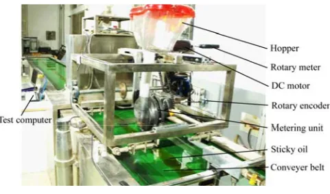
The corn drill platform in this research was a commercially- available product with four separate seeding units as shown in Figure 1a. Four seeding units were driven by land wheels through sprockets and chains as depicted in Figure 1b. The unit on the most left was modified in this research by using an electric motor with a reducer to directly drive its metering unit instead of the land wheel and the other three units remained as contrast ones for field tests in future work. Two rotary encoders of 600 PPR were used to measure the speed of the land wheel and the metering unit, respectively. A speed electronic control unit (ECU) was developed to calculate the traveling speed by reading signals from the encoder connected to the land wheel axis and transferred information in real-time through a CAN-bus communication network. A metering ECU determined appropriate voltage signals for the motor driver to maintain the metering unit at a desired rotating speed in relation to the travelling speed and the desired in-row spacing. A 4.3-inch touch screen with a RS232 port as the user interface provides functions for setting working parameters and displaying states of working components in real-time. Figure 2 illustrates the low-cost precision seeding control system with a reserved node for integrating other devices like an RTK-GPS receiver in future work.
a. Overall appearance b. Metering unit driven by land wheels c. Metering unit driven by a DC motor Figure 1 Corn drill with four seeding units
Figure 2 Precision seeding control system Parameters and variables in this research are listed in Table 1.
2.1 Calculation of travelling speed
For realizing precision seeding, true travelling speed of the corn drill needed to be detected in real-time. Since slip existed between tractor wheels and the ground, the encoder was attached to the land wheel for measuring its rotating speed as shown in Figure 1c. Since the land wheel subjected to no load, we considered that its rotation could exactly represent the travelling speed. The speed ECU read and counted pulses from the rotary encoder connected to the rotating axle of the land wheel by a fixed time
Table 1 Parameters and variables
Variable Description Unit
Vi Travel speed of the corn drill m·s-1
D Diameter of the land wheel m
Ci The number of pulses /
∆T Time interval s
N Resolution of the encoder /
K Window size of the median filter /
Sd Desired rotating speed r·min-1
V Travel speed km·h-1
Dd Desired spacing cm
Da Actual spacing cm
M The number of metering holes /
Vt Speed signal volt
Sa Actual rotating speed r·min-1
e Difference between Sa and Sd r·min-1
KP Coefficient for the proportional term /
KI Coefficient for the integral term /
KD Coefficient for the derivative term /
S′a Rotating speed by the rotatory meter r·min-1
interval ∆T, calculated the travel speed Vi by using Equation (1),
and distributed the speed information to the metering ECU through the CAN-bus network and the user interface through the RS232 port.
Δ i i
πDC
V
N T
=
⋅ (1)
where, D is the land wheel diameter, m; Ci is the number of pulses
in ∆T, and N is the encoder resolution in pulse per revolution. In consideration that speed measurements were noisy due to unevenness of the field ground, a median filtering method was used to pre-process travelling speed measurements by a window size of K as represented by Equation (2). K measurements were firstly sorted numerically and the middle value was considered as the travelling speed value.
1 0
[ ]K
i t
V Median V −
=
= (2)
2.2 Control of metering unit
The metering unit was driven directly by the DC motor to drop seeds at a desired rotating speed that was calculated by using Equation (3) and controlled in real-time according to the varying travelling speed. Figure 3 shows the metering unit control system.
1666.67
d
d V S
D M
= × (3)
where, M is the number of holes of the metering unit; Sd, V and Dd
are in r/min, km/h and centimeters, respectively.
Figure 3 Metering unit control system
The rotating speed of the seed metering unit was fed back to the metering ECU and a digital PID controller was implemented in the metering ECU to determine an appropriate control signal Vt to
the motor driver as shown in Figure 4.
Note: Sd – Desired rotating speed, Sa(i) – Actual rotating speed, e(i) – the difference between Sa and Sd, KP, KIand KD are PID parameters.
Figure 4 Digital PID controller for precision seeding
3 Results and discussion
Experiments were designed and conducted on the seeding drill test platform with a sticky belt of 5 m in length in the laboratory as shown in Figure 5. The sticky belt was driven by a frequency-conversion motor at a speed ranging at 0-12 km/h to simulate relative movement between the drill and the ground. Basic parameters including N and M, were set to 600 and 12, respectively, by using the RS232 touch screen according to the encoder and the metering unit used in this research. ∆T was fixed for each ECU and needed to be calibrated by experiments.
Figure 5 Installation of main components for laboratory tests
3.1 Calibration of rotating speed measurement of the metering unit
In order to control its rotation speed at a desired value Sd by
using the digital PID controller, the actual rotating speed Sa of the
metering unit was sampled at a certain interval, which needed to be calibrated in terms of its true value S′a because the time spent on the commands execution loop by different ECUs was different and the sampling interval was different.
The metering unit was driven by the DC motor at different speeds as shown in Table 2 according to measurements of a rotatory meter. And measurements by the speed ECU were recorded and listed correspondingly. The adjustment coefficient was calculated by Equation (4):
S′a=ksSa
(4)
where,
S
′
a is the rotating speed measured by the rotatory meter; Sais the rotating speed measured by the developed metering ECU. From Table 2, it is noticed that values of Sa are a little smaller
than those of S′a. And kS is set to the average value of kS for the
meter ECU in this research. Similar calibration was conducted for the speed ECU as shown in Table 2 and kS is set to 1.26 as its
average value.
Table 2 Calibration results for the metering ECU
S′a/r·min-1 7.98 17.17 26.63 36.29 46.41 56.28 66.64 76.81 87.47 97.40 108.06
Sa/r·min-1 7.91 16.97 26.45 36.22 46.14 56.03 66.24 76.37 86.96 97.02 107.61
kS 1.008 1.012 1.007 1.002 1.006 1.004 1.006 1.006 1.006 1.004 1.004
Table 3 Calibration results for the speed ECU
S′a/r·min-1 7.97 17.34 27.02 36.99 46.86 57.02 66.90 77.11 87.34 97.38 107.69
Sa/r·min-1 6.27 13.76 21.42 29.27 37.21 45.30 53.22 61.30 69.41 77.39 85.51
kS 1.270 1.260 1.262 1.264 1.259 1.259 1.257 1.258 1.258 1.258 1.259
3.2 Evaluation in the laboratory
To verify its validation in precision seeding, the newly-developed low-cost precision seeding control system was
over the conveyer sticky belt to prevent seeds from bouncing when dropped on the sticky belt. The speed ECU was used to measure the sticky belt moving speed by reading pulses from the rotary encoder connected to the driving shaft of the sticky belt. And the metering ECU controlled the DC motor to rotate the metering unit through a sprocket and chain mechanism at a desired speed so that corn seeds could be dropped at a predetermined spacing. The test computer was used to record and analyze data streamed from the metering ECU through a RS232 serial port.
The travelling speed V of the conveyer sticky belt was configured as different values ranging at 1.0-8.0 km/h and the desired in-row spacing Dd set to 25 cm, 30 cm and 35 cm for each
speed value. The actual spacing Da between two adjacent seeds
was measured while the sticky belt stopped. Each parameter setting was repeated to acquire adequate data for evaluating the system performance. Figure 6 shows seeds dropped on the sticky belt and variation of Da along the sticky belt length with V and Dd
set to 5.0 km/h and 25 cm, respectively.
a. Seeds dropped on the sticky belt b. Variation of Da with two large deviations in red circles
Figure 6 Evaluation of precision seeding control
From Figure 6, it can be seen that the actual in-row spacing fluctuates around 25 cm. And there are two large values away from the desired spacing due to seeding absence of the metering unit. Such values would not be considered in evaluation of the system performance. More results in detail are listed in Table 4 with Da, eRMS, emax and Sa are the average of Da, the RMS error
of Da, the maximum value of Da, and the average of Sd,
respectively.
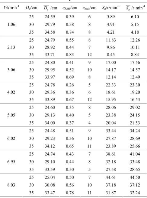
Table 4 Performance evaluation under different moving speed
V/km·h-1 D
d/cm Da /cm eRMS/cm emax/cm Sd/r·min
-1
a S /r·min-1
25 24.59 0.39 6 5.89 6.10
30 29.79 0.58 8 4.91 5.15
1.06
35 34.58 0.74 8 4.21 4.18
25 24.79 0.55 8 11.83 12.26
30 28.92 0.44 7 9.86 10.11
2.13
35 33.71 0.83 12 8.45 8.83
25 24.80 0.41 9 17.00 17.56 30 29.95 0.52 10 14.17 14.57 3.06
35 33.97 0.69 8 12.14 12.49 25 24.78 0.26 5 22.33 23.30 30 29.36 0.36 6 18.61 19.20 4.02
35 33.89 0.67 12 15.95 16.53 25 24.60 0.35 8 28.06 29.02 30 29.13 0.40 5 23.38 24.15 5.05
35 34.00 0.37 4 20.04 21.53 25 24.48 0.51 9 33.44 34.24 30 29.23 0.56 10 27.87 28.69 6.02
35 34.12 0.65 11 23.89 25.66 25 24.74 0.43 7 38.61 41.04 30 29.10 0.44 8 32.18 33.48 6.95
35 33.59 0.50 5 27.58 28.65 25 25.04 0.50 7 44.61 44.50 30 30.08 0.56 10 37.18 37.12 8.03
35 33.47 0.78 11 31.87 32.24
From Table 4, it is noticed that the average of Da deviates less
than 2 cm from the corresponding desired spacing Dd. eRMS
becomes larger when Dd is set from 25 cm to 35 cm when the belt
speed remains the same because inaccuracy in speed control of the metering unit is amplified much more when the in-row spacing increases. Friction between working parts of the metering unit slightly varies when dropping seeds, which is the reason that the maximum error emax occurs. Correspondingly, the desired rotating
speed Sd is given, which covers a wide range from 4.21 r/min to
44.61 r/min. The average of Sa is larger than its corresponding Sd
in most tests with a largest deviate of 2.43 r/min. This clearly explains that Da is smaller than Dd.
4 Conclusions
This research explored the possibility of developing a low-cost precision seeding control system that could continuously change the rotating speed of the metering unit by using an electric motor according to the travelling speed. A speed ECU was developed to read pulses from the rotary encoder attached to the land wheel, calculate and distribute the travelling speed through a CAN-bus network. The electric motor was controlled by the metering ECU to drop seeds at a desired in-row spacing while the travelling speed varied. Results in laboratory tests showed that the average of actual spacing Da deviated less than 2 cm from the desired in-row
spacing Dd and its maximum RMS error was 0.78 cm, which
indicated that the newly-developed system worked accurately and stably under laboratory environments. In future work, field tests will be conducted to further verify and improve its performance in measurement of travelling speed and variable-rate control of metering devices, which contributes as a research foundation for affordable variable-rate seeding in the field of precision agriculture.
Acknowledgements
Program of China Sub-project (No. 2017YFD0700405); and Shandong Province Science and Technology Planning Project of Higher Education (J17KA145).
[References]
[1] Samborski S M, Gozdowski D, Stępień M, Walsh O S, Leszczyńska E. On-farm evaluation of an active optical sensor performance for variable nitrogen application in winter wheat. European Journal of Agronomy, 2016; 74: 56–67.
[2] Maleki M R, Ramon H, de Baerdemaeker J, Mouazen A M. A study on the time response of a soil sensor-based variable rate granular fertilizer applicator. Biosystems Engineering, 2008; 100: 160–166.
[3] Basso B, Dumont B, Cammarano D, Pezzuolo A, Marinello F, Sartori L. Environmental and economic benefits of variable rate nitrogen fertilization in a nitrate vulnerable zone. Science of the Total Environment, 2016; 545–546: 227–235.
[4] Vleugels T, Rijckaert G, Gislum R. Seed yield response to N fertilization and potential of proximal sensing in Italian ryegrass seed crops. Field Crops Research, 2017; 211: 37–47.
[5] Reyes J F, Esquivel W, Cifuentes D, Ortega R. Field testing of an automatic control system for variable rate fertilizer application. Computers and Electronics in Agriculture, 2015; 113: 260–265.
[6] Moltó E, Martı́n B, Gutiérrez A. Design and testing of an automatic machine for spraying at a constant distance from the tree canopy. Journal of Agricultural Engineering Research, 2000; 77(4): 379–384.
[7] Li X, Zhao H, Liu Y, Jiang H, Bian Y. Laser scanning based three dimensional measurement of vegetation canopy structure. Optics and Lasers in Engineering, 2014; 54: 152–158.
[8] Gil E, Llorens J, Llop J, Fàbregas X, Escolà A, Rosell-Polo J R. Variable rate sprayer. Part 2 – Vineyard prototype: Design, implementation, and validation. Computers and Electronics in Agriculture, 2013; 95: 136–150. [9] Llorens J, Gil E, Llop J, Escolà A. Variable rate dosing in precision
viticulture: Use of electronic devices to improve application efficiency. Crop Protection, 2010; 29: 239–248.
[10] Webster C, Westoby M, Rutter N, Jonas T. Three-dimensional thermal characterization of forest canopies using UAV photogrammetry. Remote Sensing of Environment, 2018; 209: 835–847.
[11] Pawlowski A, Guzmán J L, Sánchez-Hermosilla J, Rodríguez C, Dormido S. A low-cost embedded controller design for selective spraying vehicle. IFAC-PapersOnLine, 2017; 50(1): 5404–5409.
[12] Cai J, Wang X, Song J, Wang S, Yang S, Zhao C. Development of real-time laser-scanning system to detect tree canopy characteristics for variable-rate pesticide application. Int J of Agric & Biol Eng, 2017; 10(6): 155–163.
[13] Chattha H S, Zaman Q U, Chang Y K, Read S, Schumann A W, Brewster G R, et al. Variable rate spreader for real-time spot-application of granular fertilizer in wild blueberry. Computers and Electronics in Agriculture, 2014; 100: 70–78.
[14] Jafari M, Hemmat A, Sadeghi M. Development and performance assessment of a DC electric variable-rate controller for use on grain drills. Computers and Electronics in Agriculture, 2010; 73: 56–65.
[15] Kim Y J, Kim H J, Ryu K H, Rhee J Y. Fertiliser application performance of a variable-rate pneumatic granular applicator for rice production. Biosystems Engineering, 2008; 100: 498–510.
[16] Maleki M R, Mouazen A M, Ramon H, de Baerdemaeker J. Optimisation of soil VIS–NIR sensor-based variable rate application system of soil phosphorus. Soil and Tillage Research, 2007; 94(1): 239–250.
[17] Kühling I, Redozubov D, Broll G, Trautz D. Impact of tillage, seeding rate and seeding depth on soil moisture and dryland spring wheat yield in Western Siberia. Soil & Tillage Research, 2017; 170: 43–52.