USRP 2901 Based FM Transceiver with Large File
Capabilities in Virtual and Remote Laboratory
https://doi.org/10.3991/ijoe.v14i10.8283
U. Somanaidu(*)
Institute of Aeronautical Engineering, Hyderabad, India
Nagarjuna Telagam
GITAM University, Bangalore, India
K. Nehru
Institute of Aeronautical Engineering, Hyderabad, India
N. Menakadevi
Hindustan College of Engineering and Technology, Coimbatore, India
even a more extensive scope of radio stations to the audience[6]. Smart Sensor Interface Standard, puts forward the idea of the combination of smart sensor and video, audio signal monitoring [7]. Frequency division multiplexing (FDM) is another popular tech-nique in wireless communication which is famous for the efficient high speed transmis-sion [8]. The modulated carrier contains several spectral components, requiring fre-quency domain analysis. The key concept and the underlying principle of FM and FM bandwidth dilemma are presented [9]. Software-defined radios (SDRs) promise unprec-edented flexibility, but their architecture has proven to be a challenge for MAC proto-cols [10]. After being the subject of speculation for many years, a software-defined radio receiver concept has emerged that is suitable for mobile handsets. A key step forward is the realization that in mobile handsets, it is enough to receive one channel with any bandwidth, situated in any band. Thus, the front-end can be tuned electroni-cally [11]. LabVIEW interacts with the USRP transmitter by means of four functions located on the block diagram’s palette under Hardware Interfaces is taken from this manual [12].
2
Implementation
2.1 USRP 2901 with Dual Band Vertical Antenna and Tri band Antenna
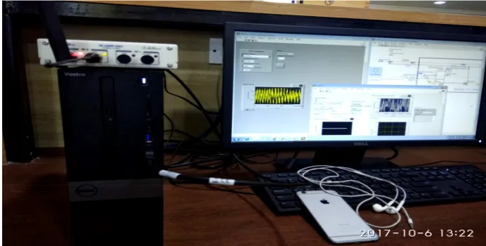
Fig. 1. Experimental set up
2.2 Working operation
A basic software defined radio system consists of computer equipped with analog to digital converter preceded by Radio frequency front end. Software radios have signifi-cant use for the military and cell phone services, both of which must serve a wide vari-ety of changing radio protocols in real time. In Fig 1 the red color indicates the signal is transmitting and green color indicates the signal is receiving. The message and carrier signal is represented in equation (1) and (2). Am and Ac are the amplitudes of signal and fm and fc are the message signal frequency and carrier signal frequency.
𝑚𝑚(𝑡𝑡) = 𝐴𝐴'cos (2𝜋𝜋𝑓𝑓'𝑡𝑡) (1) 𝑐𝑐(𝑡𝑡) = 𝐴𝐴0cos (2𝜋𝜋𝑓𝑓0𝑡𝑡) (2) 𝑠𝑠(𝑡𝑡) = 𝐴𝐴0𝑐𝑐𝑐𝑐𝑠𝑠(2𝜋𝜋𝑓𝑓0𝑡𝑡 + 𝛽𝛽 ∫ 𝑚𝑚(𝑡𝑡)𝑑𝑑𝑡𝑡) (3) 𝐵𝐵𝐵𝐵𝐵𝐵𝑑𝑑𝐵𝐵𝐵𝐵𝑑𝑑𝑡𝑡ℎ = 2(∆𝑓𝑓 + 𝑓𝑓') (4)
∆𝑓𝑓 = 𝛽𝛽 ∗ 𝑓𝑓' (5)
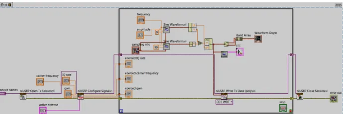
Fig. 2. FM Transmitter VI Snippet
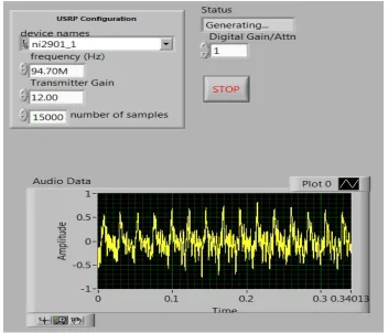
Fig. 3. Front Panel showing the controls and audio data
This VI Snippet supports large file capabilities. For large WAV files, you should choose a value other than -1 for Number of Samples. By adding a multiply function just before the Resample Waveform VI gives the digital gain or digital attenuation to the signal. Values less than 1 will attenuate the signal and values greater than 1 will am-plify the signal.
Table 2. Receiver Parameters
Parameter at Receiver Value used
Carrier Frequency 94.7MHz
IQ Rate 5M
Receiver Gain of the Verto Antenna 20
Number of Samples 15000
Digital Gain/ Attenuation 2
Coerced Gain 30
Fig. 5. USRP Receiver Front Panel
4
Conclusion
5
References
[1]https://en.wikipedia.org/wiki/FM_broadcasting
[2]Kandasamy, Nehru, et al. "Simulation of Analog Modulation and Demodulation Techniques in Virtual Instrumentation and Remote Lab." International Journal of Online Engineering (iJOE) 13.10 (2017): 140-147. https://doi.org/10.3991/ijoe.v13i10.7575
[3]Telagam, Nagarjuna, Nehru Kandasamy, and MenakadeviNanjundan. "Smart Sensor Net-work Based High Quality Air Pollution Monitoring System Using Labview." In-ternational Journal of Online Engineering (iJOE) 13.08 (2017): 79-87.
[4]Telagam, Nagarjuna, et al. "Cruise Control of Phase Irrigation Motor Using SparkFun Sen-sor." International Journal of Online Engineering (iJOE) 13.08 (2017): 192-198. https://doi.org/10.3991/ijoe.v13i08.7318
[5]Telagam, Nagarjuna, et al. "Smart Sensor Network based Industrial Parameters Moni-toring in IOT Environment using Virtual Instrumentation Server." International Jour-nal of Online Engineering (iJOE) 13.11 (2017): 111-119. https://doi.org/10.3991/ijoe.v13i11.7630 [6]Nagarjuna, T., et al. "Design and Development of Coded OFDM based Digital Audio
Broad-casting System using Concatenated Convolutional Turbo Codes."
[7]Gantala, Anil, et al. "Design of Smart Sensor Using Linux-2.6. 29 Kernel." Interna-tional Journal of Applied Engineering Research 12.18 (2017): 7891-7896.
[8]Nagarjuna, T., and S. Ganesh. "Design and Development of Hybrid Adaptation Tech-niques in MimoOfdm System for 4G Wireless Networks." International Journal of Innovative Re-search and Development 2.4 (2013): 533-546.
[9]Faruque, S. Radio frequency modulation made Easy. Springer. (2017). https://doi.org/10.1007/978-3-319-41202-3
[10]Nychis, George, ThibaudHottelier, Zhuocheng Yang, SrinivasanSeshan, and Peter Steen-kiste, Enabling MAC Protocol Implementations on Software-Defined Radios. In NSDI, 9. (2009):91-105.
[11]Abidi, Asad A. The path to the software-defined radio receiver. IEEE Journal of Sol-id-State Circuits, 42, 5(2007). 954-966. https://doi.org/10.1109/JSSC.2007.894307
[12]Lab Based Learning with NI USRP, and LabVIEW Communication Student Lab Manual, Bruce A. Black
6
Authors
Somanaidu Utlapalli received his M.Tech. (Engineering) in VLSI and Embedded system from Prakasam Enginnering college (PEC), Kandukur – 523105, India in 2014. He is currently an Assistant Professor in the Department of Electronics and Communi-cation Engineering of IARE, Jawarharlal Nehru Technological University, Hyderabad. His research area includes VLSI and Embedded System.
Department, Hindustan College of Engineering and Technology, Coimbatore, In-dia. She is a Research Fellow and is interested in the following topics: Digital Image processing, Wireless communications. Currently She is working as assistant professor. Her professional experience is about 5 years in the field of teaching. She completed Master degree M.E - communication system in Loyola institute of technol-ogy/AnnaUniversity