IJIRT 147763
INTERNATIONAL JO URNAL OF INNOVATIVE RESEARCH IN TECHNOLOGY464
Total Hormonics Distortion Reduced By Using
STATCOM
Ashish R. Totewad
1, Rajat V. Patle
2, Pratik Raut
3, Sachin Vishwakarma
4, Khushal S. Dharmik
5, Professor
Hitesh B Hatnapure
6Department of Electrical Engineering, J D college of Engineering, Nagpur
Abstract- This paper shows the analysis and modeling of S TATCOM using MATLAB S IMULINK. In this paper a electric network with two different load is chosen, after connecting each load total distortion of system will check if there is any distortion present then the electric system will be modified by using FACTS device which provide compensation to the system and reduces the total harmonics .In this type comparison of linear load and nonlinear load compensation will done with the help graph at the end of all process.
Index Terms- FACTS , S TATCOM, FFT, Harmonics, Linear Load, Non-Linear Load, Power quality, voltage profile.
I. INTRODUCTION
In 21st century the day by day we are rapidly growing in industry area. The industries large scale, medium scale, small scales are depending upon the electrical power system. So it is need to provide high electricity power continuously. As an electrical engineer it’s our responsibility to provide electricity without any distortion.
Power transmission and distribution is a more complex process because of large number of
generator transformer transmission line. the
transmission line is either linear load or non-linear load because of these linear or non-linear load the transmission system is unstable so the losses is increase because of unbalanced condition. Therefore to maintain such the power system stability there are several number of FACTS device use to maintain the voltage profile. FACTS (Flexible Alternating Current Transmission System) is defined the FACTS device is power electronic based device and other static equipment that provide control of one and more AC transmission parameters to enhance controllability and improve the power quality. The FACTS device improve the transmission quality and efficiency the system by supplying inductive or reactive power to
grid. The four type of FACTS controller series controller, shunt controller, shunt-series controller, series-series controller. the various type of FACTS devices like STATCOM,SVC, UPFC,IPFC,SSSC etc. STATCOM is a shunt connected FACTS controller power electronic based device it is more efficient than SVS and it provides greater benefits as
compared to SVS.STATCOM is a shunt
compensating device and is made up of coupling transformer, leakage inductance dc capacitor and switching convertor each of this components have its own function. As in India mostly load is inductive load in nature because of the industries development. It is necessary to maintain such type of load within the certain limits some devices and technologies are used. FACTS devices have play vital role in it. There are various types of FACTS devices but STATCOM is more efficient device for improvement of power quality and harmonic distortion.
II. STATCOM
STATCOM is a stand for static synchronous compensator. It is a regulating device used for alternating current electricity transmission networks. It is based on a power electronics voltage-source converter and can act a either a source of reactive AC power to an electricity network. If connected to a source of power it can also provide active AC power. It is a member of the FACTS devices . These compensators are also use to reduce voltage
fluctuation. The STATCOM is usually installed to support
IJIRT 147763
INTERNATIONAL JO URNAL OF INNOVATIVE RESEARCH IN TECHNOLOGY465
synchronous condenser by controlling the excitationif synchronous machine which in turn controls the amplitude of induced emf E with respect to V the reactive power flow can be controlled. The current is drawn by the synchronous compensator is certain by the system voltage V,internal voltage E and total circuit reactance x .I=V-E/X.
STATCOM consist of coupling transformer, voltage source converter, DC capacitor link. Coupling transformer used to connect the voltage source converter to the middle of transmission line.
If internal voltage (E) is greater than the system voltage (V) then the machine is over excited and leading current close in an system and the machine is seen as capacitor. Whereas or in reverse if the internal voltage then the machine is under excited and lagging current close in an AC system and the machine is seen as inductor. In STATCOM DC capacitor provides a direct current input and also it acts as a energy storage device.
A STATCOM is voltage source converter based device with voltage source behind a reactor. The voltage source is produced from a DC capacitor therefore STATCOM has very little active power capacity. The active power capability is increased if appropriate energy storage device is connected across the DC capacitor.
Magnetic coupling
Voltage source converter
DC Energy source
ESTATCOM
V
Eutility
ISTATCOM
Figure 1: STATCOM
III. SYSTEM MODEL
The system model is used of two machine system for the analysis which is shown in figure below.
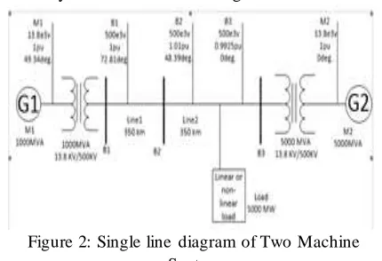
Figure 2: Single line diagram of Two Machine System
The two machine system consists of generator, busbar, transmission line, transformer and load connected to it. Basically STATCOM is used for
midpoint voltage regulation over a 500 kv
transmission line.this system clarifies the dynamic response of the s ystem.
In two machine system there are two generator i.e. generator 1(G1) and generator( G2) the generator have 1000 MVA and 5000 MVA respectively. A 1000 MVA generation plant G1 is connected to a load center through a long 500 kv,700 km transmission line .the load center is modeled by 5000 MW resistive load. The load is fed by remote generation plant G1 and local generation plant G2.Genrator 1 is connected at one end and generator 2 is connected at another end .
The transformer 1 and transformer 2 are connected in transmission line near the generator G1 and G2 respectively. Which step up the voltage level from13.8 kv to 500 kv the three bus are connected with the help of transmission line at a distance of 700 km long.
Table 1 data sheet of two machine system model
Area Devices Ratings
Area 1
Generator1 Transformer1 Transmission line1
Load
1000MVA
1000MVA,13.8KV/500KV 350KM
500MW
Area 2
Generator 2 Transformer 2 Transmission line 2 Load
5000MVA
5000MVA,13.8KV/500KV 350KM
IJIRT 147763
INTERNATIONAL JO URNAL OF INNOVATIVE RESEARCH IN TECHNOLOGY466
IV. TWO MACHINE SYSTEM ANALISIS1] LINEAR LOAD 2] NON-LINEA R LOAD
1) Linear load -
Linear load are the load which can not change with the time, its requirement of power is constant for the all time. the linear load parameter like, impendence is not changing its always maintain near the rated value. the linear load are the static load there is no any type of rotating part, because of power is transfer directly through the solid path. the load cycle of the linear load is approximately sinusoidal and the current and voltage of the load are mutually dependent. the various type of linear load are water heater, capacitor bank, CFL, indecent lamp etc.
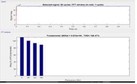
A)Linear Load Without Device - In this project we take two machine system which have two generator namely as G1 and G2 of 1000 MVA and 5000 MVA respectively. And connect the linear load of 5000 MVA,500 KV,50 HZ in the system with the help of two step up transformer of the rating of 13.8/500 KV with the length of line is 700 KM which is shown in figure no2. After simulating the system by using fast fourier transform in the MATLAB SOFTWARE we analyze the total harmonic distortion in the system. and we observe that in the linear load the harmonics is also present at some amount the total harmonic distortion in the system by connecting linear load is approximately 128.47% which is shown in figure below.
So the amount of total harmonic distortion present in the system are reduced the efficiency of the system, due to presence of the harmonic the voltage profile is not maintain stable and the large amount of power loss is occurs to overcome this type of problems in the system with linear load we have to installed any compensating device to increase efficiency, maintain voltage profile and reduced power loss as well. So for this kind of problems we installed compensating device namely as STATCOM (static synchronous compensator) which is shunt device connect in middle of the transmission line, STATCOM inject voltage in the system and change the impendence as per the requirement of system. As shown in figure (a) below
Figure (a):Linear load without STATCOM B)Linear Load Without Device - To overcome the problems in the transmission line the STATCOM is connected in middle of the the system as shown in fig,after simulating the system by using fast fourier transform in the MATLAB SOFTWARE we analyze the total harmonic distortion in the system. And from that we observe that the total harmonic distortion is reduced by using linear load with STATCOM as campared to linear load without STATCOM. The amount of total harmonics distortion present in the system is approximately 99.28% which shown in figure below.
So from the above analysis we can observe that by using compensation device in the system we can
reduced the total harmonics distortion by
approximately 20-30%. It means by using the compensating device we can improve the voltage profile of the system, efficiency of the the system and also reduced power loss.As shown in figure (b)below
IJIRT 147763
INTERNATIONAL JO URNAL OF INNOVATIVE RESEARCH IN TECHNOLOGY467
the impedance of the power distribution system. Non-linear loads are basically found in heavy industrial application such as arc furnaces, heavy rectifiers etc.we can say the definition of non-linear load as a nonlinear load is a load that draws a non sinusoidal current (distributed, contains harmonics) when subjected to a sinusoidal voltage.We perform the Nonlinear load without STATCOM device and Non -linear load with STATCOM device compare the Total Harmonic Distortion (THD) of non-linear load with or without STATCOM device.
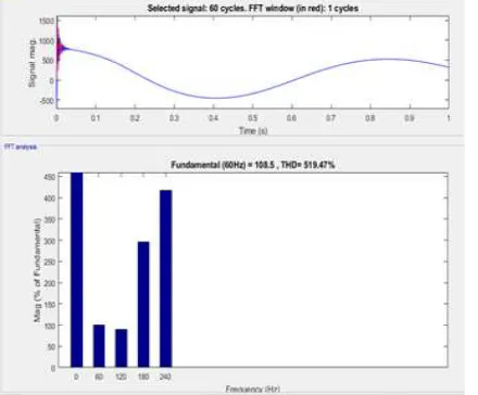
A)Non Linear Load Without Device- As shown in the figure the Non-linear load is connected in the system to found the total harmonics distortion. As two machine system consists of two generating station(G1 & G2) each having a rating of are
1000MVA and 5000MVA respectively. In
transmission line transformer is used to maintained the voltage level upto the rating of 500kv/13.8kv. These transformer are connected through the transmission line having a distance of 700km. there are three busbars in the system to indicate the voltage. after the simulation of two machine system model without the compensation we have to seen that the total harmonics distortion are very large and it is 519.47%. this harmonics causes or become a major problem in the power system. Therefore to overcome
such harmonics two machine system with
compensation is used these models reduces some of the harmonics and tries to become a system stable, maintain the voltage profile and also used to enhance the power transfer capability of transmission line.
Figure (a): Non-Linear load without STATCOM
B)Non-Linear load with Device – The device Same setup are used in this system with only one difference is that the compensation are provided in the system to maintain the voltage profile, increase transient stability of transmission line and the main objective of system is to concern with the total harmonics distortion. Obviously this system after providing compensation reduces the total harmonics distortion as the STATCOM provide compensation it is shunt connected FACTS controller power electronic based or IGBT basesd device which injects the current into the system to overcome the power quality problem. This system modal with devices reduce the harmonic distortion and it is 189.17%.If we have to seen comparison point of view two machine system without STATCOM device contain more harmonics as compare to two machine system with STATCOM device therefore without FACTS devices 519.47% and with FACTS device the harmonics are 189.17% and hence we can conclude that two machine system with STATCOM device reduces total harmonic distortion as small as possible and enhances the system stability, transit stability, maintain voltage profile of transmission line, power oscillation damping etc.
Figure (b): Non-Linear load with STATCOM
REFERENCES
[1] Hitesh B. Hatnapure, “Power Quality
IJIRT 147763
INTERNATIONAL JO URNAL OF INNOVATIVE RESEARCH IN TECHNOLOGY468
[2] Prabha Kundur, “Power System and Control”
TATA McGRAW- HILL edition
[3] M.A.Abido, A.T.AI-Awami, Y.L.Abdel-Magid,
“Analysis and Design of UPFC Damping
Stabilizers for Power system Stability
Ennhancement”, IEEE ISIE 2006, Montreal, Quebec, Canada
[4] Devendra Manikrao Holey, Vinod Kumar
Chandrakar, “Dynamic Harmonic Domain
Modelling of Space Vector Based UPFC”, American Journal of Electrical Power and Energy Systems 2016; 5(1): 1-10
[5] Priyanka k Gaurkhede, “SVPWM Based
STATCOM for Power Quality Improvemen”, ISSN 0974-2158 Volume 10, Number 1 (2017), pp. 1-12 © International Research Publication House.
[6] Tejinder Singh Saggu, Lakhwinder Singh,
“Comparative Analysis of Custom Power Devices For Power Quality Improvement in Non-linear Loads” proceedings of 2015 RAECS UIET Pnjab University Chandigarh 21-22nd Dec 2015.
[7] Zhou Xiaojie, Ruan Yi,”Modellin and simulation analysis of 3-Level VSC-STATCOM based on SVPWM”.
[8] S.Selvakumaran, “Power Quality Improvement
in Transmission Systems Using FACTS
Devices”, 2016 Online International Conference on Green Engineering and Technologies (IC-GET)
[9] Hingorani and N.G.Gyungi-“Understanding
FACTS devices”-IEEE press 2000
[10]Laszlo Gyugi, “Dynamic compensation of ac
transmission line by solid state synchronous Electric potential sources,” IEEE transaction on power delivery, Vol 9, No 2, pp: 904-911, April 1994
[11]Pushpa Chakravarty, Dr. A.K. Sharma
“Modeling and Simulation of a Distribution
Statcom (D-Statcom) For Power Quality
Problems” International Journal of Electrical and Electronics Research ISSN 2348-6988 (online) Vol. 3, Issue 1, pp: (6-11), Month: January - March 2015,
[12]S.Premalatha, G.PunithaValli, ―Digital
Simulation of D-statcom System for Improving
Power Quality‖ EEE Department, Anna
University Velammal Engineering College,
Chennai, Tamilnadu, India 2012 IEEE.
[13]J. Ganesh Prasad Reddy, & K. Ramesh