Techniques used in Li-Fi Enabled Wireless
Data Transmission: A Study
1
Swati Singh,
2Dr. Y.P Singh
1Dept. of Computer Science & Engineering, Sun Rise University, Alwar, Rajasthan, India 2Somany (P.G.) Institute of Technology & Management, Rewari, Rohtak, Haryana, India
Abstract
The modern research has made the Visible Light Communication (VLC) technology, one of the advanced optical wireless communication technologies, which is green and clean in nature. Visible Light Communication, uses visible region (375nm-780nm) and is used as a more secure medium for data transmission. it achieves high data rates as compared to conventional wireless technologies like Wi-Fi, Bluetooth, Wi-max etc. the conventional technologies uses radio waves for communication. To overcome the shortage of bandwidth we can use light to transfer the data which is known as “DATA THROUGH ILLUMINATION”. LED light bulb that varies in intensity is used and it cannot be followed by the naked eye. It is possible to encode various data in the light
by varying the light at which the LEDs flicker on and off to give
different strings of 1s and 0s.While using mixtures of red, green and blue LEDs to alter the light frequency encoding a different data channel.
Keywords
Visible Light Communication (VLC), LED, Wi-Fi, Li-Fi, Orthogonal Frequency Division Multiplexing (OFDM) or Discrete Multi-Tone (DMT), Free Space Optical (FSO).
I. Introduction
Li-Fi is a term often used to describe high speed VLC in application scenarios where Wi-Fi might also be used. The term Li-Fi is similar to Wi-Fi with the exception that light rather than radio is used for transmission. Li-Fi might be considered as complementary to Wi-Fi. If a user device is placed within a Li-Fi hot spot (i.e. under a Li-Fi light bulb), it might be handed over from the Wi-Fi system to the Li-Fi system and there could be a boost in performance.
However, to implement high speed wireless connectivity, the limited modulation bandwidth of the commercial LEDs (10-20
MHz) requires spectrally efficient modulation techniques, for e.g.
Orthogonal Frequency Division Multiplexing (OFDM) or Discrete Multi-Tone (DMT) [5].
II. Literature Survey
Development of the information communication Technology had
made a very significant researches from traditional way of sending
messages from smokes, birds, pigeons to the1st generations to the 5th generation Sending messages from one place to other place to sending a bulk data of audio, Video and doing processing simultaneously. VLC is a communication medium for data, which uses visible light ranges between 400 THz (780 nm) and 800 THz (375 nm) as a optical carrier for data transmission and illumination. It uses fast pulses of light to transmit information wirelessly. The main components of this communication system are:
1) a high brightness white LED, Which used as a communication source and 2) a silicon photodiode which act as a good responder to visible wavelength region serving as the receiving element. LED can be switched on and off several times to produce digital
strings of 1s and 0s as a data. Data can be encoded in the light
to produce a new stream of data by varying the flickering rate of
the LED bulb. It can work, by modulating the LED light and the data signal, the LED illumination act as a communication source .This paper uses the concept of the cost effective clean and green technology of the communication. It will simplify the essence of communication requirement of life at one end and also used to save the energy at another end. It will help in boosting our economy, as our power requirement will be at the saving end.
A. Techniques Used
In the basic method, an image can be transmitted using light over a distance. The basic components are shown. Here the data which can be audio or image can be transferred using different light sources and can be received at the receiver, it can be processed and converted back to original transmitted data. There are various
methods and some of them are explained briefly.
Component based information is given.
B. Techniques used in Li Fi enabled Wireless Data Transfer Using Modulators
Here modulators are used extensively to enable data transfer. The basic components of the system are discussed below.
1. Communication Using RS 232 Serial Port
Data transfer within a system is generally in parallel. All the bits of the data where transferred in parallel at the same instant from a digital system. In some cases, particularly in transferring data over long distances, it is preferred to transfer the data in serial form. The data word from a transmitting system is converted to stream of serial bits, and one bi is transferred on a single line to a receiving system at a time. At the receiving end, the data is reconstructed by serial to parallel conversion.
The speed of data transmission in serial communications is
specified by baud rates. Asynchronous data transfer is used
for the serial communication which is done at a lower speed, typically at standard rates such as 2400, 4800, 9600, 19200 baud etc. The synchronizing clock or timing signal are not used in the asynchronous communication.
Information being transferred between data processing equipment and peripherals is in the form of digital data which is transmitted in either a serial or parallel mode. Parallel communications are used mainly for connections between test instruments or computers and printers, while serial is often used between computers and other peripherals.
Serial transmission involves the sending of data one bit at a time, over a single communications line. In contrast, parallel communications require at least as many lines as there are bits in a word being transmitted (for an 8-bit word, a minimum of 8 lines
are needed). Serial transmission is beneficial for long distance
or when very high transmission rates are required.
2. Standards
One of the advantages of a serial system is that it lends itself to transmission over telephone lines. The serial digital data can be converted by modem, placed onto a standard voice-grade telephone line, and converted back to serial digital data at the
receiving end of the line by another modem. Officially, RS-232 is defined as the “Interface between data terminal equipment
and data communications equipment using serial binary data
exchange.” This definition defines data terminal equipment (DTE)
as the computer, while data communications equipment (DCE) is the modem. A modem cable has pin-to-pin connections, and is designed to connect a DTE device to a DCE device.
3. Interfaces
In addition to communications between computer equipment over telephone lines, RS-232 is now widely used for direct connections between data acquisition devices and computer systems. As in
the definition of RS-232, the computer is data transmission
equipment (DTE). However, many interface products are not data communications equipment (DCE). Null modem cables are designed for this situation; rather than having the pin- to-pin connections of modem cables, null modem cables have different internal wiring to allow DTE devices to communicate with one another.
4. Cabling options
RS-232 cables are commonly available with either 4, 9 or 25-pin wiring. The 25-pin cable connects every pin; the 9-pin cables do not include many of the uncommonly used connections; 4-pin cables provide the bare minimum connections, and have jumpers to provide “handshaking” for those devices that require it. These jumpers connect pins 4, 5 and 8, and also pins 6 and 20. The advent of the IBM PC AT has created a new wrinkle in RS-232 communications. Rather than having the standard 25-pin connector, this computer and many new expansion boards for PC’s feature a 9-pin serial port. To connect this port to a standard 25- pin port, a 9-to-25-pin adaptor cable can be utilized, or the user
can create his own cable specifically for that purpose.
Free space optical (FSO) communication is similar to VLC but is not constrained to visible light, so ultraviolet (UV) and infrared (IR) also fall into the FSO category. Additionally, there is no illumination requirement for FSO and so this tends to be used in narrow beams of focused light for applications such as communication links between buildings. FSO often uses laser diodes rather than LEDs for the transmission.
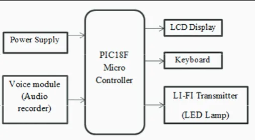
Fig. 1: Showing the Li-Fi Enabled Audio Transfer
Most of white LEDs is comprised of LED chip emitting short wavelength and wavelength converter (for example, phosphor). The short wavelength light from the LED chip is absorbed by the phosphor and then the emitted light from the pho sphor experiences wavelength shift to a longer wavelength. As a result, the many wavelength components are observed outside the LED. A white light can be generated from a blue LED with appropriate phosphor. The emission spectrum of a phosphor based LED has the strong original blue spectrum and the longer wavelengths shifted by the phosphor.
1W Power LEDs are high performance energy efficient devices
which can handle high driving current and high temperatures. The exposed pad design enables excellent heat transfer from the package to the motherboard. An electrically isolated metal slug option is also available.
The White Power LED is available with color temperatures
ranging from 2700K to 10000K. The low profile package design
is suitable for a wide variety of applications especially where height is a constraint and the package foot print is compatible with most high power LEDs available in the market today. Shows the block diagram of the real-time audio broadcast system. Which consists of a VLC wireless LOS link with two optical channels. VLC is free space optical communication, and line of sight (LOS) is the common link between two points in optical wireless communication system. where the transmitter directs the visible light beam in a straight and unobstructed path to the receiver. the prototype for data transmission.
The voice module is analog signal(audio signal).The microcontroller
is connected to lifi transmitter and its converting the audio signal
into the electrical signals and electrical signals is converted to light signals using optoisolator.A constant current is applied across the LED and by varying the current very fast, the optical output can be made to vary at high speeds, the transmitting side will transmit the data and its connected to array of LEDs through which the data is transferred.
Audio signal are amplified by a self-designed amplifier and then
superimposed onto two LED lamps respectively by the aid of a bias-T circuit. Thus, the output light rays changes in intensity corresponding to the variation in signal, which however is insensitive to human eyes due to the rapid frequency response of LED devices. The transmitter circuit is given. At the receiver, two highly sensitive Si PIN photodiodes are used to detect light transmitted over two separate optical channels. After detection, optical signals are converted into photo electric current proportional
to the variation of incident light. which then is amplified and filtered by a low pass filter (LPF).
An audio with USB interface is designed to convert the received analog signal into digital signal. Finally, the audio is played real time on the screen of a further processing such as simple cutting,
filtering or storing. In the proto-type, transmission distance of
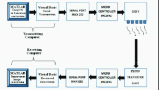
Fig. 2: Showing the Basic Overview of Li Fi System Using LED Arrays
C. Techniques used in Li Fi enabled wireless data transmission of an image:
To transmit an image from one PC to another PC using VLC the following steps can be followed. A software called MATLAB has to be used for image processing at the transmitting end and also for reception at the receiving PC. Atmega 89c2051 microcontroller is used fortoggling LED at the transmitter. It can be used again for binary conversion of received data into a suitable image to be recognized by the PC software. A domestic LED is used as a source of light in this system. laser source is the best choice due to its coherence and reliability properties.
Fig. 3: Showing the Image Transfer Using Li-Fi
Steps involved are as follows:
A written program which will execute in the system and take
•
the image as an input and split it into pixels and then transmit it through serial port.
A hardware device take the data serially from the computer
•
and then convert these binary data streams into optical (light) data streams and vice – versa.
A signal converter to convert RS 232 signal to TTL logic
•
signal and TTL logic signal back to RS 232 signal.
A written program at the other end to convert this serially
•
received pixel data back into an image and then display it on the computer.
1. Description of Block Diagram
(i). Input Interface-Each input port is connected to a bridge rectifier
which converts AC to DC (and DC input remains unaffected)The
rectified voltage is then passed through a RC-filter (3 resistors
with R=4.7 ohms/2W connected in series and C=10uF, 415V) to moderate the ripples. IC 7805 voltage regulator has been used to produce an output of 5V dc.
2. Transmitter Section
MAX -232 is used to convert the signals from the PC RS - 232 serial port to TTL compatible signals to be used by the microcontroller. Atmega 89c2051 microcontroller has been used for conversion
of these decimal signals to binary signals which hence flicker the
LED for data transmissionA crystal of frequency 11.0592 kHz provides clock pulses to the microcontroller.
3. Receiver Section
L14G2 NPN- phototransistor has been used which receives the LED pattern in binary form The microcontroller converts this data back into decimal form to be retrieved.MAX-232 converts these TTL logic levels back to serial logic levels used by the RS-232 of the receiving PC LM 324 comparator has been used at the source (LED) for quantizing the data bits received via the photo-diode.
4. Techniques used in Li Fi enabled wireless data transfer using LASER
Laser Communication is one of the emerging area of wireless communication system. Due to its low noise ratio makes its one of the well-suited communication medium for exchange of information. Currently laser commutation is adopted in satellite communication for space research activities and due to its
efficiency on low noise ratio, inexpensive, low power and its flexibility and its resistance to the radio interferences makes laser
communication as one of research area in wireless communication. In this process, this thesis comprises the one such application of laser communication for information exchange between any two devices.
In Laser Communication, the transmitter and receiver must require line-of-sight conditions and Laser communications systems have
the benefit of eliminating the need for broadcast rights and buried
cables. The carrier used for the transmission signal is typically generated by a laser diode. Two parallel beams are needed, one for transmission and one for reception. Laser communications systems are wireless connection through the atmosphere. Which is focused on decreasing the noise ratio in optical communication system?
Laser communications systems work similarly to fiber optic
links, except the beam is transmitted through free space. In Laser Communication, the transmitter and receiver must require line-of-sight conditions and Laser communications systems have the
benefit of eliminating the need for broadcast rights and buried
cables. Laser communications systems can be easily deployed since they are inexpensive, small, low power and do not require any radio interference studies. The carrier used for the transmission signal is typically generated by a laser diode. Two parallel beams are needed, one for transmission and one for reception.
temporary connectivity needs (e.g. sporting events, disaster scenes, or conventions), or space based communications.
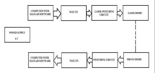
Laser communication system can be used to transmit sound and data signals through the laser beam of the system. The intensity of the carrier beam changes with the change in amplitude of the sound signal. Variation in the intensity of the laser beam is converted into a variation in the voltage level by using solar panel. In this mode of communication, the transmitter and receiver requires to satisfy the line of sight conditions. The carrier required for transmission of signal in laser communication system is generated by laser diodes.
Laser communication is one of the key area in wireless Communications. This includes analysis, optimization, and design and system level development of signal transformation between
satellites or any two sources. Which work similarly to fiber optic
links, except the beam is transmitted through free space. While the transmitter and receiver must require line-of-sight conditions,
they have the benefit of eliminating the need for broadcast rights
and buried cables. Laser communications systems can be easily deployed since they are inexpensive, small, low power and do not require any radio interference studies. The carrier used for the transmission signal is typically generated by a laser diode. Two parallel beams are needed, one for transmission and one for reception.
Fig. 4: Block Diagram of Wireless Data Transfer Using LASER
III. Advantages of Li-Fi
Although the use of light in order to transmit data can be limited in comparison to radio waves, there is a great amount of possibilities that can be developed due to LI-FI technology. In essence, a single pixel of a monitor could transmit a single channel of information to a source. Although LI-FI Technology is still in its infant stage, the usefulness of this LI-Fi Technology has Implications for a great amount of Goods.
High speed, as high as 500mbps or 30GB per minute
•
Li- Fi uses light rather than radio frequency signals,
•
VLC could be used safely in aircraft,
•
Integrated into medical devices and in hospitals as this
•
technology does not deal with radio waves, so it can easily be used in such places where Bluetooth, infrared, Wi-Fi and internet are banned. In this way, it will be most helpful transferring medium for us.
Under water in sea Wi-Fi does not work at.
•
There are around 19 billion bulbs worldwide, they just need
•
to be replaced with LED ones that transmit data. We reckon VLC is at a factor of ten, cheaper than WI-FI.
Security is another benefit, he points out, since light does not •
penetrate through walls.
In streets for traffic control. Cars have LED based headlights, •
LED based backlights, and Car can communicate each other and prevent accidents in the way that they exchange
Information. Traffic light can communicate to the car and
so on.
Every street lamp would be a free access point.
•
Li-Fi may solve issues such as the shortage of radio frequency
•
bandwidth.
IV. Disadvantages
Still there are some backdrops like it can only transmit when in the line of sight well it can be sorted out someday and will be used in some applications.
V. Conclusions
There are a numbers of reasons why investing in LI-Fi technology
can have a great benefit to the future of wireless networking.
Although there are a few aspect that need to be ironed out before it can be introduced on a wide scale of practicality, the future looks to be very promising. Even if the technology was merely developed as a small scale indoor application to beam information directly to a computer system without the use of Ethernet cable being
strewn about the floor, visible light communications could set the
benchmark higher for wireless transmissions. Beside the above it is also proven and may come forward in the days ahead with the developments of the LI-FI Technology.With the Development of the technology, and its application for the industrial use. It can be put in to practical application. Every bulb/LED can be used something like a WIFI hotspot to transmits wireless data. By the implementation of the technology we will proceed towards the cleaner, greener and safer brighter future. The possibilities are numerous and can be explored further. The concept of Li-Fi is attracting a great interest, because it may provide a very
efficient and genuine alternative to radio-based wireless. Proposed
research Scheme shall be shown as a result oriented study of high speed wireless data transmission and reception using visible light spectrum and in addition to transfer the power through wireless
and be an efficient energy saving alternative of Wi-Fi .
References
[1] R. Abu-alhiga, H. Haas,“Subcarrier-Index Modulation OFDM,” In Proc. of the International Symposium on Personal, Indoor and Mobile Radio Communications (PIMRC), Tokyo, Japan, Sep. 13– 16, 2009.
[2] Li-Fi The Future Technology In Wireless Communication.
[3] [Online] Available: http://www.transeem.org/Upload/files/
TEEM/10%20JEEMT10- 027(238-241).pdf(project) [4] R. Abu-alhiga, H. Haas,“Subcarrier-Index Modulation
OFDM,” In Proc. of the International Symposium on Personal, Indoor and Mobile Radio Communications (PIMRC), Tokyo, Japan, Sep. 13– 16, 2009.
[5] Li-Fi The Future Technology In Wireless Communication.
[6] [Online] Available: http://www.transeem.org/Upload/files/
TEEM/10%20JEEMT10- 027(238-241).pdf(project) [7] Novel Feedback and Signaling Mechanisms for Interference
Management and Efficient Modulation
[8] Visible Light Communications: challenges and Possibilities Dominic C. O'Brien, Lubin Zeng1, Hoa Le-Minh, Grahame Faulkner, Joachim W. Walewski, Sebastian Randel,University of Oxford (UK); Siemens AG, Corporate Technology, Information and Communications, Munich.
[10] H. Helperin,W.Hu, A Sheth, D Wetherall, 802.11 with Multiple Antennas for dummies, University of Washington and intel lab, Seattle.
[11] [Online] Available: http//www.profheath.org/MIMO-Communication /single-user-mimo/
[12] S.M. Alamouti,“A simple transmit diversity technique for wireless communications,” IEEE J. Sel. Areas Commun., Vol. 16, pp. 1451–1458, Oct. 1998.
[13] V. Tarokh, N. Seshadri, A. R. Calderbank,“Space-time codes for high data rate wireless communications: performance criterion and code construction,” IEEE Trans. Inf. Theory, Vol. 44, pp. 744–765, Mar. 1998.
[14] H. Viswanathan, S. Venkatesan,“The impact of antenna diversity in packet data systems with scheduling,” IEEE Trans. Commun., Vol. 52, pp. 546–549, Apr. 2004. [15] D. Tse, P. Viswanath,"Fundamentals of Wireless
Communication", Cambridge University Press, 2005. [16] R.Gallager,“Low-density parity-check codes,” IEEE Trans.
Inf. Theory, Vol. 8, No. 1, pp. 21–28, Jan. 1962.
[17] C. Berrou, A. Glavieux, P. Thitimajshima,“Near Shannon limit error correcting coding and decoding: Turbo-codes”, Proc. IEEE Int’l Conf. in Communic. (ICC’93), pp. 1064– 1070, May 1993.
[18] M. A. J. Goldsmith,“The capacity of downlink fading channels with variable rate and power,” Vol. 46, pp. 569–580, Aug. 1997.
[19] Transmit Diversity vs. Spatial Multiplexing in Modern MIMO Systems, Angel Lozano, Senior Member, IEEE, and Nihar Jindal, Member, IEEE with and without frequency diversity,” Bell Syst. Tech. J., Vol. 49, No. 8, pp. 1827–1871, Oct. 1970.
[20] M. Schwartz, W. R. Bennett, S. Stein,"Communication Systems and Techniques", New York: McGraw-ill, 965. ng transmitter diversity and channel coding,” IEEE Trans. Veh. Technol., Vol. 33, pp. 37–43, Feb. 1984.
[21] J Kennedy, Davis, Prasanna,“ Electronics Communication system”, 5E, Tata Macgraw hills publications Pvt ltd, New-Delhi, India, 2008 edition.
Swati Singh, received the B.TECH. Degree in Computer Science and Engineering from Uttar Pradesh Technical University in 2008 and M.TECH degree from Karnataka State University and is pursuing PhD from Sunrise University, Alwar. Presently she is working as Assistant Professor in the Department of Computer Science & Engineering, IMS Engineering College, Ghaziabad.