JETIRCQ06034 Journal of Emerging Technologies and Innovative Research (JETIR) www.jetir.org 195
Electrical Substation Earthing Design
Ishan M. Desai
Assistant Professor, Electrical Engineering Department,
Parul Institute of Engineering and Technology, Parul University, Vadodara, India
Abstract: Earthing is the most important part of any substation for reliable operation in substation. Earthing is provided in substation to protect equipment from getting failed and human from getting shocked in abnormal system condition. In this paper, design procedure of electrical substation earthing is explained. Through these design steps, calculation of earthing can be done easily. Calculation of earthing grid design parameters whether grid is of single area or two area can also be done. It also shows whether provided design is safe or not by comparing maximum tolerable & calculated step and touch voltage. Earthing grid area will be large as compared to substation switchyard area to ensure safety in substation.
Index Terms - Substation, Earthing, Step Voltage, Touch Voltage, Earthing Grid
I.EARTHING
It is important to provide earthing in all the parts of electrical power system wherever required, whether it is provided in power generating station, transmission line or substation. It is very much important from point of view of protection of equipment and human safety. Substation is the most important place in power system where equipments like power transformer, circuit breaker, instrument transformer etc. are connected together to convert or control power between two ends of power system. All these equipments must require provision of earthing for safe and reliable operation. In substation, earthing must be provided with neutral point of transformer, reactor and with lightning arrester and with non-current carrying metal parts like structure, overhead shielding wire, body part of equipments, frames etc. for safety purpose. Human safety is also one of the main reasons behind provision of earthing in substation.
II.TYPESOFEARTHING
There are two types of earthing provided in substation. One is earthing mat or grid and other is earthing pit. Earthing pit in most the cases is pipe type earthing shown in Fig. 1 provided with lightning arrester and neutral part of transformer as well as reactor. Other than these, rest of the equipment body part, structures etc. are connected with earthing grid. Earthing grid shown in Fig. 2 is array of rod of specific dimension buried at required depth to keep the step and touch voltage within limit. Generally, the area of earthing grid has to be more than area of switchyard as all the required point in switchyard including fencing of switchyard which has to be connected with earthing grid for safety purpose. Earthing grid system can also be classified by number of area i.e. one area earthing grid and two area earthing grid which also affects the design of earthing in substation.
III.SUBSTATIONEARTHINGGRIDDESIGN
3.1 Size of Earthing Grid Conductor
Earthing Grid Conductor Size can be calculated by
Amm2=
I
√(TCAP∗ 10−4 tcαrρr ) ln (
K0+Tm
K0+Ta)
(1)
Where,
I = Symmetrical grid current in kA αo = Thermal coefficient of resistivity
Amm2 = Conductor cross section αr = Thermal coefficient of resistivity at reference temperature
Tm = Maximum allowable temperature ρr = Resistivity of the ground conductor at reference temperature Ta = Ambient temperature tc = Duration of current in sec
Tr = Reference Temperature for material constants TCAP = Thermal capacity per unit volume Ko = 1/ αo
After calculation of earthing grid conductor cross section, corrosion factor needs to be multiplied as per different ranges of resistivity of soil as per CBIP publication 223 [5] as grid conductor which in general is used of GI may get corrode because of soil moisture. Hence, conductor cross section needs to be multiplied with corrosion factor after which it will be verified that standard size of conductor which is actually used in grid is more than calculated which proves that used conductor will give safe design.
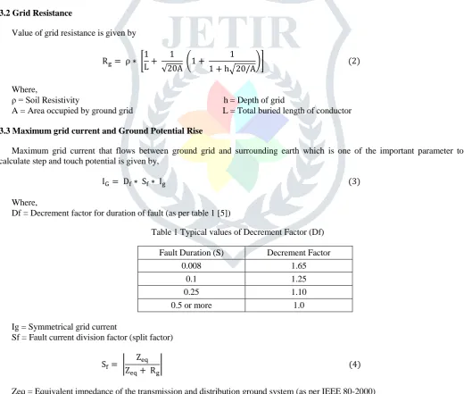
3.2 Grid Resistance
Value of grid resistance is given by
Rg= ρ ∗ [ 1 L+
1
√20A (1 +
1
1 + h√20/A)] (2)
Where,
ρ = Soil Resistivity h = Depth of grid
A = Area occupied by ground grid L = Total buried length of conductor
3.3 Maximum grid current and Ground Potential Rise
Maximum grid current that flows between ground grid and surrounding earth which is one of the important parameter to calculate step and touch potential is given by,
IG= Df∗ Sf∗ Ig (3)
Where,
Df = Decrement factor for duration of fault (as per table 1 [5])
Table 1 Typical values of Decrement Factor (Df) Fault Duration (S) Decrement Factor
0.008 1.65 0.1 1.25 0.25 1.10 0.5 or more 1.0 Ig = Symmetrical grid current
Sf = Fault current division factor (split factor)
Sf= | Zeq Zeq+ Rg
| (4)
Zeq = Equivalent impedance of the transmission and distribution ground system (as per IEEE 80-2000) Ground Potential Rise is given by
GPR = IG∗ Rg (5) 3.4 Step and Touch Voltages
JETIRCQ06034 Journal of Emerging Technologies and Innovative Research (JETIR) www.jetir.org 197
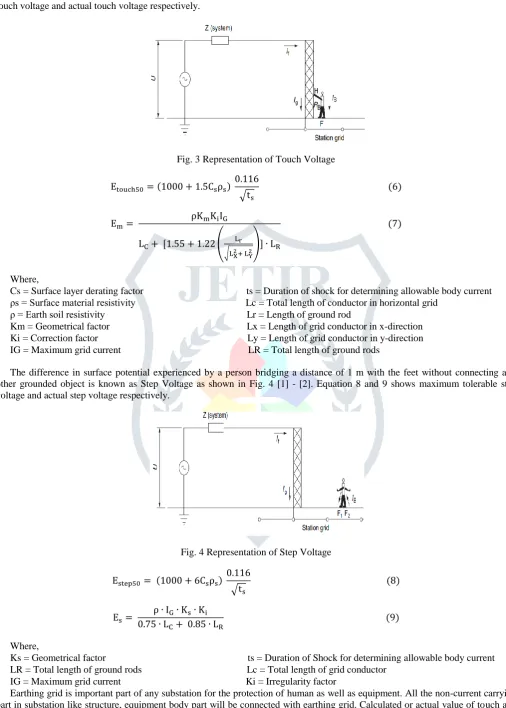
with a grounded structure is known as Touch Voltage as shown in Fig. 3 [1] - [2]. Equation 6 and 7 shows maximum tolerable touch voltage and actual touch voltage respectively.
Fig. 3 Representation of Touch Voltage
Etouch50= (1000 + 1.5Csρs) 0.116
√ts
(6)
Em=
ρKmKiIG
LC+ [1.55 + 1.22 (
Lr
√LX2+ LY2 )] ∙ LR
(7)
Where,
Cs = Surface layer derating factor ts = Duration of shock for determining allowable body current ρs = Surface material resistivity Lc = Total length of conductor in horizontal grid
ρ = Earth soil resistivity Lr = Length of ground rod
Km = Geometrical factor Lx = Length of grid conductor in x-direction Ki = Correction factor Ly = Length of grid conductor in y-direction IG = Maximum grid current LR = Total length of ground rods
The difference in surface potential experienced by a person bridging a distance of 1 m with the feet without connecting any other grounded object is known as Step Voltage as shown in Fig. 4 [1] - [2]. Equation 8 and 9 shows maximum tolerable step voltage and actual step voltage respectively.
Fig. 4 Representation of Step Voltage
Estep50= (1000 + 6Csρs) 0.116
√ts
(8)
Es=
ρ ∙ IG∙ Ks∙ Ki 0.75 ∙ LC+ 0.85 ∙ LR
(9)
Where,
Ks = Geometrical factor ts = Duration of Shock for determining allowable body current LR = Total length of ground rods Lc = Total length of grid conductor
IG = Maximum grid current Ki = Irregularity factor
Earthing grid is important part of any substation for the protection of human as well as equipment. All the non-current carrying part in substation like structure, equipment body part will be connected with earthing grid. Calculated or actual value of touch and step voltage has to be less than maximum tolerable value. Also, value of earth resistance should be less than below given values:
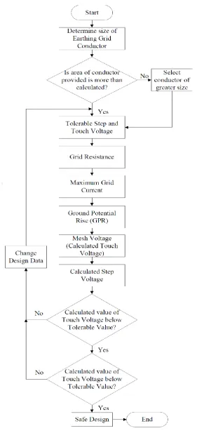
Care needs to be taken while designing earthing grid. All the design steps mentioned above for designing substation earthing grid as per IEEE 80-2000 are given in flow chart form in Fig. 5.
Fig. 5 Earthing Grid Design Steps
IV.DESIGNCALCULATIONANDANALYSIS
Considering substation switchyard of 132 kV having area of 165 X 96 meters whose earthing grid is to be designed with following data:
Symmetrical fault current in substation (Ig) = 32000 A
Duration of fault current for sizing ground conductor (tc) = 1 Sec Surface layer resistivity (ρs) = 3000 Ωm
JETIRCQ06034 Journal of Emerging Technologies and Innovative Research (JETIR) www.jetir.org 199
Length of Grid conductor in X direction (Lx) = 170 m Length of Grid conductor in Y direction (Ly) = 100 m Spacing between parallel conductors (D) = 10 m No. of Grid conductor in X direction (Nx) = 11 No. of Grid conductor in Y direction (Ny) = 18 Length of Ground rod at each location (Lr) = 3 m Number of rods placed in area (Nr) = 10
Decrement factor for determining IG (Df) = 1.0 Equivalent earthing mat area (A) = 17000 m2
Total length of Buried Conductor (L) = 3700 m Total length of ground rods (LR) = 30 m
For earthing conductor material, the following parameters have to be considered [1]: Maximum Allowable Temperature (or Fusing Temperature) (Tm) = 419 °C
Ambient Temperature (Ta) = 50 °C
Reference Temperature for material constants (Tr) = 20 °C Thermal coefficient of resistivity at 0°C (αo) = 0.00341
Thermal coefficient of resistivity at reference temperature (αr) = 0.0032 Resistivity of the ground conductor at reference temperature (ρr) = 20.1 Thermal capacity per unit volume (TCAP) = 3.93
Following above parameters, calculated value of touch voltage comes out to be 120.19 V which is less than allowable touch voltage of 732.48 V. Also, calculated value of step voltage comes out to be 93.74 V which is less than allowable step voltage of 2437.77 V. So, the design of earthing grid is safe. Soil resistivity is the parameter which affects step and touch potential in earthing grid design. Both step and touch voltage increases with increase in soil resistivity as shown in Fig. 6.
Fig. 6 Relation between Soil Resistivity and Step & Touch Voltage
V.CONCLUSION
Design of substation earthing grid can be done reliably and easily with design steps given as per flow chart of Fig. 5 according to IEEE 80-2000. Provided design steps can give safe design of electrical substation earthing grid with accuracy. From design steps, it can be observed that soil resistivity affects the step and touch voltage. Soil resistivity affects Grid Resistance as well. Also, parameters like spacing between parallel conductors, depth of ground grid conductors affects step and touch voltages which are the most important parameters in design of substation earthing grid.
VI.REFERENCES
[1] IEEE Guide for Safety in AC Substation Grounding, Institute of Electrical and Electronics Engineers, IEEE Std. 80-2000, IEEE, 2000.
[2] McDonald, J. D. 2006, Electrical Power Substation Engineering, CRC Press, pp. 184-207.
[3] Satnam, P. S. and Gupta, P. V. 2006, Substation Design and Equipment, Dhanpat Rai Publications, pp. 184-207.
[4] Code of Practice for Earthing, Indian Standard, IS: 3043, IS, 2001.