National Conference on Advances in Engineering and Applied Science (NCAEAS) 29th January 2018
Organized by : Anjuman College of Engineering and Technology (ACET) Nagpur, Maharashtra, India, In association with
International Journal of Scientific Research in Science and Technology
GPS Based Vehicle Tracking and Engine locking System
Mr. Anurag Rajendra Bharadkar, Mr. Mukesh Kumar Hansraj , Mr. Shubham Devidas Harshe, Ms. Pooja Keshav Walke , Ms. Sneha Gangadhar Ghule
Department of Electronics and Telecommunication Engineering , Guru Nanak Institute of Technology, Nagpur, Maharashtra, India
ABSTRACT
Security systems and navigators have always been a important part of human‟s life. The developments of advanced electronics have brought revolutionary changes in these fields. In this paper, we will present a vehicle tracking system that use a GPS module and a GSM modem to find the location of a vehicle and offers a range of control features. To complete the design successfully, a GPS unit , a relay, a GSM Modem and a MCU units are used. There are five features made known in the project. The purpose of this project is to remotely track a vehicle‟s location, remotely switch ON and OFF the vehicle‟s ignition system and remotely lock and unlock the doors of the vehicle. An SMS message is sent to the tracking system and the system acknowledges to the users request by performing convenient actions. Short text messages are authorized to each of these features. A webpage is specifically designed to view the vehicle‟s location on Google maps. By using relay based control concept introduced in this paper, number of control features such as turning heater on/off, radio on/off etc. can be execute in the same fashion.[1]
I.
INTRODUCTION
The vehicle tracking system is an electronic device that tracks the vehicle‟s location. Most of the tracking systems use GPS module to locate the vehicle‟s position .Many systems also interface communication components such as satellite transmitters to communicate the vehicle‟s location to a remote user. Google maps are used to view the vehicle‟s location. The design of the tracking system is divided into three parts; basic design, intermediate design and an advance Design. The basic design of the vehicle tracking system consists of a GSM module, a GPS module, a MCU (ATMEGA 32), a Relay circuit and a LCD. The user sends SMS and the
to the user with the location coordinates (i.e. Longitude and Latitude). These coordinates can be used to view the location of a vehicle on Google maps. The vehicle tracking system presented in this paper comprises of a cost effective and special tracking technology. The tracking systems are not only bounded to shipping industry and fleet tracking but also used in cars as a theft prevention tool.
This paper provides an overview of the background analysis related to vehicle tracking and control systems, component‟s choice and full development process of the tracking system. The paper is divided in five main sections: related research, choice of components, design of a system, simulation of designs and implementation process. In the related research section, we will outline the research carried out so far. Then, we will discuss the components used. The design section will focus the software and hardware design process. The assembly of components will be explained in the implementation section. Finally, the implementation process section will include the software simulations and images of the hardware in working condition.[2]
II.
RELATED RESEARCH
There are n number of papers has been published on the development of vehicle tracking system using GPS and GSM Modem differential GPS algorithm that is capable of providing real-time near PPP service is presented In error sources in GPS measurement are calculated ,vehicle navigation application is presented. A web application and a mobile application related to vehicle tracking are
system and GPS are discussed in great detail. A novel method of vehicle tracking is presented in using wireless sensor technology, passive sensors, android based tracking self-power tracking system and tracking system based on cloud computing infrastructure. A vehicle tracking system based on color histogram distance and binary information is implemented. In development of real-time visual tracking system for vehicle safety applications is discussed and the concept of focus of expansion (FOE) is introduced. A low cost real time tracking system that provides accurate localizations of the tracked vehicle is presented in .Vehicle tracking coupled with vehicle registration number recognition is introduced in Following huge demand of accurate vehicle tracking systems, researchers proposed number of novel methods to improve the accuracy of tracking systems.[3]
III.
CHOICE OF COMPONENTS
1. The Microcontroller unit (MCU)
Figure 1. Microprocessor
However, MCUs have a CPU in addition to the
fixed amount of RAM, ROM and I/O ports,
which are embedded on a chip with
support functions such as a crystal oscillator,
timers and serial or analog input output (I/O)
The MCUs are designed for embedded
applications and can be used in remote
controls, power tools, toys and other
appliances. Invention of MCUs has reduced
the size and cost of designs. MCUs are suitable
where cost and space are critical. There are
four types of MCUs (8 bit): 8051 family,
PIC, Zilog and Freescale. The MCU families
are not compatible with each other,
which means, if we write a code for 8051 MCU
it will not work on PIC MCU. This is
mainly due to different instructions and
registers set in each MCU.
Figure 2. AT MEGA 32 IC
To choose among these MCUs, there are specific criteria set for designers: MCU should meet the task at hand efficiently and cost effectively. Software development tools such as compilers, assemblers and debuggers should be available in the market Wide availability and reliable sources of the MCU used. Designer should also consider the speed, Packaging, power consumption, the amount of RAM, ROM on chip and cost per unit [6]
(a) (b)
Figure 3. (a) PIC Microcontroller (b) Zilog Microcontroller
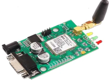
2.GSM Modem
Fig.4. A GSM Modem(Global System for Mobile Communications).
3. GPS Modules
The first GPS (navigation system) was designed by Honda in 1983 Pioneer claims to be the first with a GPS-based auto navigation system, in
1990 Magellan claims to have created the first GPS-based vehicle navigation system in the U.S in 1995.
Each GPS (satellite) transmits data that indicates the current time and its location. It transmits signals to a GPS receiver. This receiver requires an unobstructed view of the sky, so they can only be used effectively outdoors.[8]
Figure 5.
GPS Module
4 .Vibration Sensor
Vibration sensor is capable of measuring vibration of the engine when it starts. If the vehicle met
an accident, the sensor will send voltage equivalent to the intensity of hit, to the microcontroller at once. Then microcontroller sends a notification to the owner/contact list as SMS, if the sensed signal voltage is greater than or equal to some stored threshold value.
So this will be helpful to report any accidents occurring at night. Thus we use this sensor for security of rider. There are two threshold values one to detect intrusion and another to detect accidents. In the security system piezoelectric sensor is used. It is generated by pressure on certain crystals which will develop a potential difference or voltage on the crystal face. If the crystal oscillates, an AC voltage is formed. The sensor is modelled as a charge supply with a shunt capacitor and resistor, or as a voltage source with series capacitor and resistor.[9]
IV.
PROCESS OF THE SYSTEM
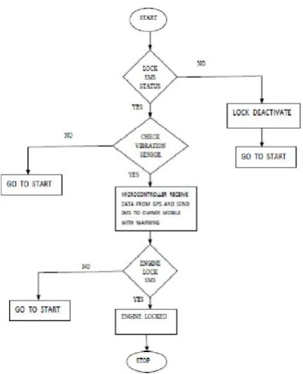
Figure 7. Flow chart of the system
The embedded system is installed in the engine of the vehicle along with GSM and GPS module. The instrument allows to active the 5V and then ignition of the engine will start, hence start the vehicle. The instrument has two modes of operation ,one is user mode and second one is theft mode .When engine will start ,then the instrument will check the lock status, if it is the owner engine will start as user mode and no SMS will be send to owner but if it is somebody else ,theft mode comes into practice and it gives as SMS notification to the concerned party as programmed that is the vibration sensor in the instrument will sense the value of the vibration of the engine.
V.
RESULTS AND DISCUSSION
In this paper, we proposed design of unique engine locking system to control seizing of vehicles using GSM and GPS technology based embedded system. The instrument has simple design, low cost, compact and reliable. This instrument can change by setting lock status field. If the vehicle accessed by unauthorized person, then owner get SMS and lock the system using the password. The delay incurred for engine locking is 2-5 minutes.[11]
If the engine will vibrate more than 10 sec ,then the sensing value is given to the microcontroller. If the value is greater than the threshold value then sending a message “Engine Started” through GSM mobile to owner‟s mobile for the further action for prevention of the vehicle theft.
After receiving this message the owner can send password „#‟ for getting the current location of the vehicle, then the longitude and latitude will be received by the owner. If the owner will send password „*‟
,then the owner can lock the engine of the vehicle through this password and receiving a message “Engine Locked” and “current location” is also include As part of the message.[10]
VI.
CONCLUSION
Day by day the vehicles increasing so as theft, on the basis of this we can be generate the proposed system that is helpful. When accidents occur during the night time, the incident can report immediately as SMS to the owner‟s contact list so that the injured persons can be hospitalized as soon as possible. As future improvement we can add extra features to the proposed system by using hidden cameras in the front and back side of the vehicle so that the details like number of
that we can take the details for further investigate, on procedure.[12]
VII.
ACKNOWLEDGMENT
We express our gratitude and thanks to the Head of our department Mrs.Sucheta Raut, who has helped us a lot in the successful completion of initial phase of our project. We remember the invaluable support offered by Dr. Sudhir Shelke , our project guide and for his good suggestions and constant encouragement.We extend our sincere thanks to our co-guide Mr. Amar Banmare and Mr.Deepak Deshpande who has given his valuable time for us and support.
VIII.
REFERENCES
[1]. A. EI-Rabbany, Introduction to GPS: The Global Positioning System, Norwood, MA: Artech House,2006.
[2]. M. Brain, "How Microcontroller Works," HowStuffWorks,a division of InfoSpace LLC, [3]. H D Pham, M Drieberg and C C.
Nguyen,"Development of vehicle tracking system using GPS andGSM modem," in IEEE Conference on Open Systems(ICOS), Kuching , 2013.
[4]. M Ahmad Fuad and M Drieberg, "Remote vehicletracking system using GSM Modem and Google map," inIEEE Conference on Sustainable Utilization andDevelopment in Engineering and Technology (CSUDET),Selangor , 2013.
"Vehicle Tracking and Locking System Based on GSM and GPS,"
[7]. P P Wankhade and P S Dahad, "Real Time VehicleLocking and Tracking System using GSM and GPSTechnology-An Anti-theft System," International Journalof Technology And Engineering System(IJTES),
[8]. P Verma and J Bhatia, "Design and Development of GPSGSMbased Tracking System with Googlemap basedMonitoring," International Journal of Computer Science,Engineering and Applications (IJCSEA),
[9]. T Le-Tien and V Phung-The, "Routing and TrackingSystem for Mobile Vehicles in Large Area," Fifth IEEEInternational Symposium on Electronic Design, Test and Application, [10]. P Fleischer, A Nelson, R Sowah and A.
Bremang,"Design and development of GPS/GSM based vehicletracking and alert system for commercial inter-city buses,"IEEE 4th International Conference on Adaptive Science &Technology (ICAST),