Article
Real-Time Performance of Mechatronic PZT Module
Using Active Vibration Feedback Control
Francesco Aggogeri1,*, Alberto Borboni 1, Angelo Merlo 2, Nicola Pellegrini 1 and Raffaele Ricatto3
1 Department of Mechanical and Industrial Engineering, University of Brescia, via Branze, 38, 25123 Brescia,
Italy; [email protected] (A.B.); [email protected] (N.P.)
2 CE.S.I Centro Studi Industriali, via Tintoretto, 10, 20093 Cologno Monzese, Italy; [email protected]
3 FIDIA Spa, c.so Lombardia, 11, 10099, Torino, Italy; [email protected]
* Correspondence: [email protected]; Tel.: +39- 030-3715579
Abstract: This paper proposes an innovative mechatronic piezo-actuated module to control vibrations in modern machine tools. Vibrations represent one of the main issues that compromise seriously the quality of the workpiece. The active vibration control (AVC) device is composed by a host part integrated with sensors and actuators synchronized by a regulator, able to make a self-assessment and adjust to the environmental alteration. This study presents the mechatronic model based on the kinematic and dynamic analysis of the AVC device. To ensure a real time performance, a H2-LQG controller has been developed and validated by simulations involving machine tool, PZT actuator and controller models. The hardware-in-the-loop (HIL) architecture is adopted to control and attenuate the vibrations. A set of experimental tests has been performed to validate the AVC module on a commercial machine tool. The feasibility of the real time vibration damping is demonstrated and the simulation accuracy is evaluated.
Keywords: real-time control; mechatronics; PZT actuators; vibration; hardware-in-the-loop
1. Introduction
In modern machine tools, mechatronics may play a key role in improving machining performances and guaranteeing high quality and efficiency. Over the past years, many researches have been developed to identify innovative solutions to minimize the undesirable effect of vibrations that compromise seriously the quality of the workpiece. This study aims at dealing with control and mitigation of vibrations in machining, proposing an innovative mechatronic device based on piezoelectric stack actuators. An active module is presented, composed by a host part integrated with sensors and actuators synchronized by a regulator able to make a self-assessment and adjust to the environmental alteration. In this way, mechanical dynamics and the control theories have been examined in designing smart piezoelectric structures.
The practice of piezoelectric materials as actuators of vibration control has been proved with success over the past twenty years [1,2], nevertheless this field is still growing in terms of exploration and progress [1]. Vibrations represent one of the main issues that affect the quality of a workpiece and they need to be considered from the design phase of a machine tool. They are usually classified in three main categories: free, self-induced and forced vibrations. The first type of vibrations is related to pulsating excitations and it has a broad range of origins, such as imperfection of materials, inertia forces from mobile parts or shocks transmitted by foundations. The second class of vibrations, known as chatter as well, is produced during the cutting process itself and they are induced by the unpredictability of the cutting phase. The last group of vibrations is generated by periodically varying forces due to bearing abnormalities, unstable effects, intermittent cutting, faulty gears, impact and motion of the foundations.
stable, stiff and able to damp vibrations. State of art shows a broad range of designs to reduce the weight of machine structures using innovative materials and achieving kinematic and dynamic performances [3-5].
Instead, the compensation-based methods include both traditional methods, called passive controls, and active control strategies. Passive controls aim at optimizing machine working parameters or using dampers and vibrations absorbers. They are not expensive, nevertheless they may negatively impact on machine efficiency and productivity. The alternative methods are the active controls, based on structural systems able to alter machine dynamics by installing smart actuators and vibrations sensors forming a closed-loop.
State of art proposes a number of mechatronic applications on active vibration control [6]. Usually, these systems focus on smart bearings solutions, single degree of freedom piezo actuators or voice coils applications [7]. Mechatronic products in the field of micro electro-mechanical systems (MEMS) are piezoelectric acceleration sensors, micro-actuators and micro-pumps [8-12]. In particular, Shan et al. [13] presented two control techniques based on axis frame mounted with a PZT transducer. Zhang et al. [14] conducted strain rate feedback control to suppress unwanted vibration of a manipulator with flexible parts. Flexible parallel manipulators are also used to achieve high structural vibration suppression using direct output feedback control [15].
To identify the most suitable strategy, a study of vibration sources and frequencies is required. In machine tool analysis, the frequency modes are associated to the structural parts [16, 17] (commonly at low frequency), tool, spindle system [18] (influenced by rpm / speed) and material workpiece [19, 20]. Figure 1 summarizes the exciting frequency ranges of a set of materials in milling and turning machining. In general, hard material workpieces may generate vibrations with frequencies in a range below 200Hz, while the frequency range defined from 160Hz to 350Hz is connected to machining of common steel materials. Light alloy materials have frequencies greater than 300Hz. The undesirable effect of vibrations appears on the displacement of tool tip point that generates irregularity, making the workpiece surface unacceptable for product quality.
This study presents an innovative active mechatronic module that aims at controlling and mitigating vibrations forced by a set of undesirable processes in the machine, such as unbalanced rotating masses, issues on gears, faulty bearing, etc. As shown above, the main sources of vibrations are connected to manufacturing operations and environment conditions, an active control of vibration provides a number of advantages in avoiding potential breakdowns of machine to reduce vibrations, gaining highly efficient machining and guaranteeing the required workpiece quality.
Figure 1. Summary of machine tool modal frequency ranges in turning and milling machining [21]
and validate the active vibration control (AVC) module. The experimental outcomes are congruent with the Finite Element analysis confirming the design assumptions.
2. Active Vibration Control (AVC) module: principles and technical features
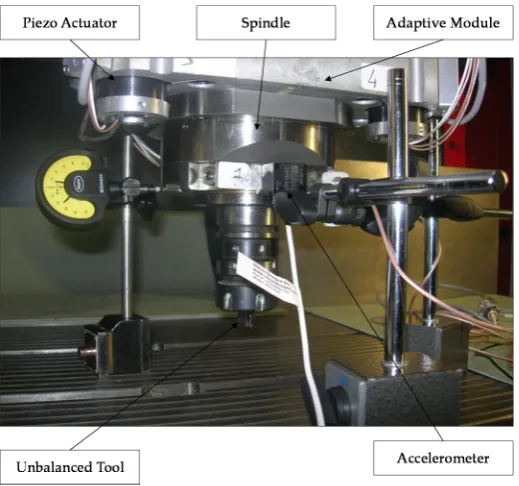
This novel module is a smart element that deals with the vibration mitigation in micro-cutting processes. The main principle is to screen the vibratory frequency, controlling the displacement at tool tip point of the machine. The proposed approach integrates mechatronic and control theories since the design phase. The device aims at increasing the quality of workpiece finishing through an AVC architecture based on high performance PZT-actuators. It is originated from the Stewart platform [22-26], but it has only 3 DOFs (2 rotation on X, Y axes and a displacement on the Z direction). Figure 2 shows an overview of the AVC system, that includes 2 platforms. The fixed platform is bounded to the machine tool vertical axis, instead the mobile is linked to the frame of the spindle. Three PZT multi-stack actuators permit the relative movement of these 2 platforms. The functional concept focuses on the recognition of undesirable displacements at tool tip point. When a deviation is measured, 3 actuators are switched on in order to smooth pulsations and their consequences on the surface quality. The piezo-electric element is able to manage compressive axial loads, but it needs a precaution with tensile and/or shear forces, for this reason special flexures have been designed and integrated to prevent any breakage or failure.
Figure 2. 3D CAD Module overview
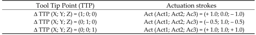
Considering the XYZ plane of Figure 2, Table 1 explains the motion strategy of the AVC device. An undesirable displacement on X axis of the tool tip point is compensated by a differential movement of the actuators. Supposing the mobile plate of platform as a rigid body, the kinematic correlation between displacement at tool tip point and actuation strokes is shown in Table 1.
Table 1. Kinematic correlation between displacement at tool tip point and actuation strokes
Tool Tip Point (TTP) Actuation strokes
Δ TTP (X; Y; Z) = (1; 0; 0) Act (Act1; Act2; Ac3) = (+ 1.0; 0.0; ‒ 1.0)
Δ TTP (X; Y; Z) = (0; 1; 0) Act (Act1; Act2; Ac3) = (‒ 0.5; 1.0; ‒ 0.5) Act (Act1; Act2; Ac3) = (+ 1.0; 1.0; + 1.0)
Δ TTP (X; Y; Z) = (0; 0; 1)
In this way, the AVC module may be pointed out as a black block between two interfacings of the machine tool. The movement of smart block is actuated by 3 piezo-electric stack actuators, which are located in a strategical position. The piezo electric actuation is regulated by the strains with sub-micron range sensitivity. A triaxial accelerometer converts the strokes at the tool tip point to be transformed in voltage of PZT-displacement. The AVC module is also equipped by a set of sensors (force, temperature and displacement) useful to permit and monitor the system functionalities.
2.1 The Mechatronic Model
electrical, control and energy engineering. The first step is to evaluate the machine tool behaviour using a set of simulations. In this way, a mechanical model may be represented by a Finite Element (FE) analysis. FE aims at describing the main characteristics of the machine tool, focusing on structural parts, links and piezoelectric actuators (Fig. 3). This study was developed on a commercial milling machine and the simulation results are presented in Table 2 and Figure 3. The FE model consists of approximately 150,000 elements.
Table 2. Comparison between experimental and numerical mode and frequencies.
Mode FE Model Freq [Hz]
Experimental Freq [Hz]
Damping
1 19 21.6 0.17
2 24 24.3 0.09
3 30 34.8 0.04
6 53 49.1 0.03
7 61 59.3 0.02
8 71 68.2 0.05
10 80 84.1 0.04
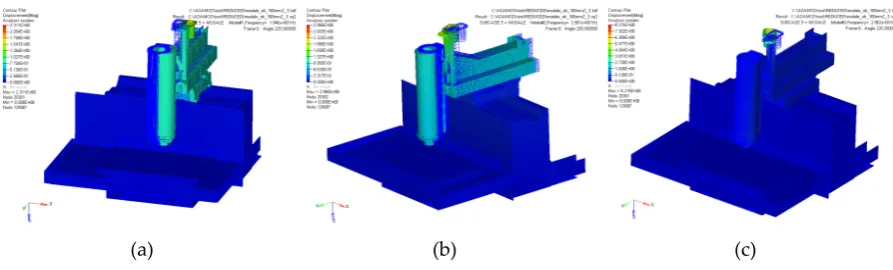
To validate the simulation results, an experimental modal analysis was performed using the “hummer test”. Table 2 shows a comparison between the FE model frequencies and experimental data at different modes. The FE frequency modes are congruent with the experimental data, confirming the robustness of the numerical model. Figure 3 highlights a set of FE analysis examples.
(a) (b) (c)
Figure 3. The FE Mode 1-3, respectively at 19 Hz (a), 24Hz (b) and 30Hz (c)
In particular, FE analysis was replicated to evaluate the impact of the AVC device. It was noted that the mechatronic module introduced a frequency mode at 280 Hz, close to the critical frequency range for a standard milling operation. The aim of the control strategies was to suppress this mode and all others improving the dynamic behavior of the machine tool.
The model was reduced in accordance to Craig and Bampton technique [27-29] in order to facilitate the dynamic simulations and testing. In this way, the degrees of freedom (DOFs) of any substructure were classified as boundary or internal. The basic assumption was that the sub-structure was characterized by defining the constrained modes and a few of normal modes. In fact, it was useless to consider a large number of modes, as only a few of them had a physical meaning. Starting from the “FE model”, a ”Reduced FE” with a few number of DOFs has been identified.
In addition, the energy dispersion quantification of structural objects through vibration depended by several damping criteria. Damping parameters could not be quantified from similar structures or predicted by the Finite Element analysis.
In this study, the damping is supposed viscous and influenced by frequency. The assumption is to consider the damping condition as a linear formulation of mass and stiffness properties:
]
[
]
[
M
K
where α and β are variables to be identified, while [M] and [K] are respectively the mass and stiffness matrices. The benefit of this construction is that the damping formulation is a diagonal matrix. The damping proportion ξ is associated to α and β through the following relation:
⋅
⋅
+
⋅
⋅
=
2
2
i i iω
β
ω
α
ξ
, (2)with ω is the Eigen-frequency of i-th mode number. The method applied to find damping characteristics is a part of the normalized ranges, known as half-power bandwidth technique. The results show that α varies from 0.05 to 0.10 while β is close to 9 x 10⁻⁶. In particular, it is noted that the mass is proportional to damping, when α is greater than β.
Another critical point in defining the mechatronic model is the representation of the state space. This procedure aims at illustratinga system of n-first order differential equations. Therefore, the use of matrices simplifies the mathematical structure of the system equations. The growth of state variables, inputs and outputs does not influence the complexity of these calculations. An AVC system and regulator need to work in real-time and for this reason the device behavior has to be explored in the time variable.
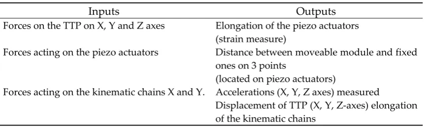
The state space (SS) model is derived from the corresponding FE model and it describes the dynamic behavior of the architecture using mathematical formulations. The dynamic scheme defines the coherence between the input and output parameters. Table 3 summarizes the SS model that has been created to control the device starting from the FE results.
Table 3. State Space Model variables.
Inputs Outputs
Forces on the TTP on X, Y and Z axes Elongation of the piezo actuators (strain measure)
Forces acting on the piezo actuators Distance between moveable module and fixed ones on 3 points
(located on piezo actuators)
Forces acting on the kinematic chains X and Y. Accelerations (X, Y, Z axes) measured
Displacement of TTP (X, Y, Z-axes) elongation of the kinematic chains
In order to perform the simulation, the reduced FE model has been analyzed using Matlab-Simulink software. The reduced form is:
{ }
M
⋅
z
+
{ }
V
⋅
z
+
{ }
K
⋅
z
=
F
, (3) where z represents the path of movements of real DOFs, F is the forces, {M} and {K} are the mass and stiffness matrices and {V} is the damping matrix. Defined vector x(t), the matrices of state A, input B, output C and D are deduced from the modal investigation. The dynamics of structure are defined by the SS form as follows:{ }
{ }
{ }
C
x
{ }
D
u
y
F
u
u
B
x
A
x
z
z
x
⋅
+
⋅
=
→
=
⋅
+
⋅
=
→
=
0
(4) with
−
−
=
− −]
0
[
]
[
]
[
]
[
]
[
]
[
1 1
−
=
−]
0
[
]
[
M
1B
,{C} and {D} depend on selected variables, x is the state vector and u represents the energy vector. The SS model of the AVC device may be created using FORTRAN code. This configuration is assimilated to SIMULINK to provide the dynamic reaction of the exhibited assembly (machine tool and AVC module) under defined perturbations.
2.2 Control modeling and strategies
The definition of the control strategy plays a key role in guaranteeing the AVC module functionality. State of art presents a broad range of techniques to control AVC systems, that may be classified in two main categories: active feedforward controllers and linear feedback regulators [30-36]. The first group of controllers has the advantages to provide the stability properties and the straightforward physical implementation. Nevertheless feedforward controllers may create a set of issues with a nonlinear feedback. The linear controllers are based on the regulator design, able to manage any potential differentiation between the plant and the model [37].
A number of researches prefer to use linear representations for control strategy and simulation when micro-movements are examined [31-34, 37]. The speed of the feedback architecture has a critical impact on the vibration dominance of smart assemblies.
In this study, a linear controller has been selected, in so far it is especially useful to control vibrations in flexible structures. As defined in SS model, linear control methods have been considered using simulations to optimize the controller implemented in the real-time hardware. In order to decrease the vibration effect, a supervisor has been analyzed to manage the required signals (e.g. voltage). In this configuration, the perturbation signal of the TTP is an input of the regulator to be sent to the PZT-actuator in recovering the displacement. Vibration suppression has been evaluated using the MIMO (Multiple Input - Multiple Output) layout and H2-LQG regulator that provide the chance to drive many actuators and manage huge sensor data [31, 32] in reducing the white noise troubles.
LQG (Linear Quadratic Gaussian) optimal control is briefly introduced. An adjusted regulator factor may be achieved by reducing the following function:
(
)
∞⋅
⋅
+
⋅
⋅
=
0
)
(
)
(
)
(
)
(
t
T T
LQG
y
t
Q
y
t
u
t
R
u
t
dt
J
, (7)where Q represents the power matrix of the device output and R is the device input matrix.
Linear Quadratic Gaussian (LQG) method may be useful and effective in real manufacturing environments. In addition, the H2 formulation replaces the stochastic reading of the LQG technique using the downsize of the 2-norm of the closed-loop structure. This choice avoids to read factors such as the strength of white noise practices that pass through LQG tricky as stochastic information [36-39]. A closed loop control system needs to guarantee stability, performance and robustness. These proprieties may be satisfied by evaluating the sensitivity function S and complementary sensitivity function T. In particular, the sensitivity S regulates the disturbance on the output of the control scheme while the complementary sensitivity T is significant for the closed-loop reaction and noise measurement. In particular, a robust control system design has to reduce S and T respectively at low and high frequencies and avoid vibration peaks.
{ } { }
{ }
{ } { }
{ } { }
C
x
D
w
y
u
D
x
C
z
u
B
w
B
x
A
x
⋅
+
⋅
=
⋅
+
⋅
=
⋅
+
⋅
+
⋅
=
21 2 12 1 2 1
(8)Equations (8) show the SS calculation, where x is the state vector, u is the control vector and w the is the input, z is the controlled variable (movement of TTP) while y is the recorded output. The H2 control requires to realize a regulator where:
)
(
)
(
)
(
s
G
s
w
s
z
=
wz , (9)such that Gwz 2is negligible.
In this way, the H2 dynamic regulator assumes that:
x
K
u
y
K
x
K
C
K
B
A
x
c e e c⋅
−
=
⋅
+
⋅
⋅
−
⋅
−
=
(
2 2)
(10)
where Ke and Kc are solutions of Filter Algebraic Riccati Equation - Control Algebraic Riccati Equation [39]. The proposed solution is simple to manage nevertheless the assumptions restrict H2 optimization to the LQG framework.
2.3 Hardware-in-the-loop (HIL) validation
In order to validate the mechatronic model a set of simulations has been performed using Simulink sw. The simulations involved the machine tool, PZT actuator and controller models. In particular, the PZT actuator linear model has been included into the reduced machine tool representation.
The main objective was to validate any integrated model testing different control schemes. A preliminary verification focused on a perturbation created by a digital input (sin-signal) to recreate the TTP displacement plotted in time-domain. The simulation wanted to represent the undesirable unbalanced tool rotation at 11500 rpm. The control model was tested in both conditions (off/on) highlighting the effectiveness of the control system by 30-50% in terms of displacement amplitude reduction, as shown in Figure 4.
Figure 4. Simulation of Activated / Deactivate states of control of a unbalanced rotation at 11500 rpm
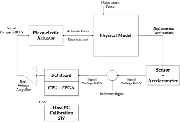
Figure 5. Hardware-in-the-loop validation architecture
3. Experimental tests and results
A set of experimental tests was performed to validate the AVC system. As shown above, the control schemes have been previously simulated by Simulink, then uploaded on the dSpace control pc. The main objective was to prove the feasibility of the control scheme using the acceleration as feedback. The choice to use the acceleration could complicate the evaluation of feedback signal but it was able to represent a broad range of applications. In this case the displacement feedback could not be taken into consideration as it was a relative measurement.
Figure 6. Experimental test overview
Figure 7 presents the obtained results. For each spindle frequency, the effect of the AVC module is clearly visible in reducing the vibration impact.
Figure 7. Experimental test of unbalanced spindle at different speed considering On - Off control
Figure 8. FRF of X axis with control (red line) and without control (blue line)
The FRF of Figure 9 underlines the comparison between the residual steady state of vibration amplitude and the uncontrolled states. The AVC module provides a suppression performance by 30-35% at 380Hz. Tables 4 summarizes the main obtained results from experimental tests.
Figure 9. Residual Vibration Peak reduction percentage on X axis
Table 4. Experimental real time effectiveness.
Frequency Range [Hz]
Control OFF [Peak Magnitude]
Control ON [Peak Magnitude]
Peak Reduction [%]
230 – 240 8.92 7.01 21.4%
370 – 380 19.36 12.98 32.9%
4. Discussion and conclusion
by Craig-Bampton technique. The mechatronic model focused on the definition of SS equations and the identification of the most suitable regulator. It was designed and optimized by using a linearized model. To ensure a real time performance a H2-LQG controller was developed. In order to validate the mechatronic model a set of simulations were performed using Simulink sw. The simulations involved the machine tool, PZT actuator and controller models. An algorithm was implemented on an integrated circuit board which receives data from accelerometer and provides the required voltage to actuate PZTs in TTP displacement recovery. A set of experimental tests was executed to validate the AVC system using a commercial machine tool and a FPGA based controller. The experimental results show the AVC performance in reducing the displacement of the spindle TTP of in 250-400 Hz frequency range.
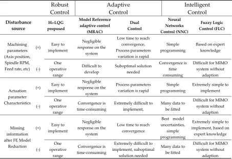
In this study, the selection of control scheme has played a key role in result achievement. State of art presents a significant number of control schemes and algorithms. Authors have identified the main advantages (+) and disadvantages (-) for each approach, as shown in Table 5. This classification is developed considering a set of disturbance sources (e.g. manufacturing parameters, actuation model and model reduction) and the type of control method.
Table 5. Trade-off comparison of different control approaches
Robust Control Adaptive Control Intelligent Control Disturbance source
H2-LQG
proposed Model Reference adaptive control (MRAC) Dual Control Neural Networks Control (NNC) Fuzzy Logic Control (FLC) Machining parameters (Axis position, Spindle RPM, Feed rate, etc)
(+) Easy to implement
Negligible response on the
system
Low time to reach convergence, Process parameters
variation is rapid
Simple programming
Based on expert knowledge (-) One operative range Difficult to develop Suboptimal solution needed Convergence is time consuming
Difficult for MIMO system without
adaption
Actuation parameter Characteristics
(+) Easy to implement
Negligible response on the
system
Process parameters variation is rapid
Simple programming
Extremely simple to implement (-) One operative range Convergence is time-consuming
Extremely difficult to implement,
Many data to be fitted
Difficult for MIMO system without
adaption
Missing information after FE Model
Reduction
(+) Easy to implement
Negligible response on the
system
Low time to reach convergence
Best model uncertainties,
simple programming
Extremely simple to implement, based on expert knowledge (-) One operative range Convergence is time-consuming
Extremely difficult to implement, suboptimal
solution needed
Many data to be fitted
Difficult for MIMO system without
adaption
1 State of art of control techniques [41-49].
References
1. Vepa, R. Dynamics of Smart Structures. John Wiley & Sons Ltd,2010.
2. Piefort, V. Finite Element Modelling of Piezoelectric Active Structures. Université Libre de Bruxelles,2001. 3. Ashby, M.F.; Evans, A.G.; Fleck, N.A.; Gibson, L.J.; Hutchinson, J.W.; Wadley, H.N.G. A Metal Foams,
Design Guide. Butterworth-Heinemann, Oxford, 2000.
4. Archenti, A.; Nicolescu, C. M. Model-based Identification of Dynamic Stability of Machining System. 1st International Conference on Process Machine Interaction - Proceedings, Hannover, Germany, 2008.
5. Schmitz, T.L.; Ziegert, J.C.; Canning, J.S.; Zapata, R. Case study: a comparison of error sources in high-speed milling. Precision Engineering, 32, 2008, 126–133.
6. Denkena, B.; Möhring, H.-C.; Will, J. C.; Sellmeier, V. Stability considerations of an piezo-electric adaptronic spindle. wt-online 9, 2006, 669-675.
7. Kern, S.; Roth, M.; Abele, E.; Nordmann, R. Active Damping of Chatter Vibrations in High Speed Milling Using an Integrated Active Magnetic Bearing. Adaptronic Congress, Göttingen, 2006.
8. Gad-el-Hak, M. MEMS Handbook. Boca Raton: CRC Press, 2000.
9. Madon, M. Fundamentals of microfabrication. Boca Raton, FL: CRC Press, 2001.
10. Lyshevski, S. E. Nano- and micro-electro-mechanical systems. Boca Raton, FL: CRC Press, 2001. 11. Janocha, H. Actuators, basics and principles. Berlin: Springer,2004.
12. Slatter, R., & Degen, R. Micro actuators for precise positioning applications in vacuum. Proceedings of the 9th international conference on new actuators Actuator 2004, Bremen, Germany, 2004.
13. Shan, J.; Liu, H. T.; Sun, D. Slewing and vibration control of a single-link flexible manipulator by positive position feedback (PPF). Mechatronics, vol. 15, no. 4, 487–503, 2005.
14. Zhang, X.; Mills, J. K.; Cleghorn, W. L. Flexible linkage structural vibration control on a 3-PRR planar parallel manipulator: experimental results. Proceedings of the Institution of Mechanical Engineers I: Journal of Systems and Control Engineering, vol. 223, no. 1, 71–84, 2009.
15. Zhang, Q.; Mills, K.J.; Cleghorn L.W. Trajectory tracking and vibration suppression of a 3-PRR parallel manipulator with flexible links. Multibody System Dynamics, 1–34, 2013.
16. Altintas, Y.; Brecher C.; Weck M.; Witt S. Virtual machine tools. Annals of the CIRP 54, 2005, 651–674. 17. Catania, G.; Mancinelli, N. Theoretical–experimental modeling of milling machines for the prediction of
chatter vibration. International Journal of Machine Tools and Manufacture 51, 2011, 339–348.
18. Cao, Y.; Altintas, Y. Modelling of spindle-bearing and machine tool systems for virtual simulation of milling operations. International Journal of Machine Tools and Manufacture 47, 2007, 1342–1350.
19. Bravo, U.; Altuzarra, O.; Lopez de Lacalle, L.N. Stability limits of milling considering the flexibility of the workpiece and the machine. International Journal of Machine Tools and Manufacture 45, 2005, 1669–1680. 20. Campa, F.J.; Lopez de Lacalle, L.N.; Celaya, A. Chatter avoidance in the milling of thin floors with
bull-nose end mills: model and stability diagrams. Journal of Machine Tools and Manufacture 51, 2010, 43–53. 21. Dequidt, A.; Castelain, J.M.; Valdes, E. Mechanical pre-design of high performance motion
servomechanisms. Mechanism and Machine Theory 35, 2000, 1047–1063.
22. Dietmair, A.; Zulaika, J.J.; Sulitka, M.; Bustillo, A.; Verl, A. Lifecycle impact reduction and energy savings through lightweight eco-design of machine tools. 17th CIRP International Conference on LCE, China, 2010. 23. Zulaika, J.J.; Campa, F.J.; Lopez de Lacalle, L.N. An integrated process–machine approach for designing
productive and lightweight milling machines. International Journal of Machine Tools and Manufacture, Volume 51, Issues 7–8, 2011, Pages 569-660.
24. Altintas, Y.; Woronko, A. A Piezo Tool Actuator for precision turning of hardened shafts. CIRP Annals—Manufacturing Technology 51,2002, 303–306.
25. Denkena, B.; Gummer, O.; Will, C.; Hackel F. Compensation of static and dynamic tool deflections during milling processes by an adaptronic spindle system. Proceedings of the 2nd International Conference on Innovative Cutting Processes & Smart Machining, Cluny, France, 2008.
26. Drossel, W.G.; Wittstock, V. Active spindle support for improving machining operations. CIRP Annals—Manufacturing Technology 57,2008, 395–398.
27. Radecki, P.; Kruse, W.; Welsh, A.; Moro, E.; Park, G.; Bement, M. Improving a turning process using piezoelectric actuators. Proceedings of the IMAC-XXVII, Orlando, FL, 2009.
29. Craig, R.R.; Bampton, M.C.C. The coupling of substructures for dynamic. AAIA6, 1968, 1313–1319.
30. Ghareeb, N.; Weichert, D. Combined multi-body-system and finite element analysis of a complex mechanism. Proceedings of the 11th SAMCEF User Conference, Paris, 2009.
31. Fan, J. P.; Tang, C. Y.; Chow, C. L. A multilevel superelement technique for damage analysis. International Journal of Damage Mechanics, vol. 13, 2004, 187–199.
32. Hughes, P. C. Space structures vibration modes: How many exist which ones are important. IEEE Control Systems Magazine, 1987, 22–28.
33. Raja, S.; Sinha, P. K.; Prathap, G.; Bhattacharya, P. Influence of one and two dimensional piezoelectric actuation on active vibration control of smart panels. Aerospace Science and Technology 20 9-216, 2002, 6. 34. Gawronski, W.K. Advanced Structural Dynamics and Active Control of Structures. Springer, NY, 2004. 35. Li, F. M.; Song, Z. G.; Chen, Z . B. Active vibration control of conical shells using piezo-electric materials.
Journal of Vibration and Control 18, 2012, 2, 234–2256.
36. Zhou, K.; Doyle, J.C. Essentials of Robust Control. Prentice-Hall, 1998.
37. Robl, C.; Englberger, G.; Farber, G. H2-Control with acceleration feedback for a micro positioning system. Proceedings of the 1999 IEEE International Conference on Control Applications, 1999, 187–192.
38. Lin, J. C.; Nien, M. H. Active control of a composite cantilever beam with piezo electric damping-modal actuators/sensors. Composite Structures 70, 2005, 170–176.
39. Zapateiro, M.; Karimi, H.R.; Luo, N.; Phillips, B.M.; Spencer Jr. B.F.A mixed H2/HN-based semiactive control for vibration mitigation in flexible structures. Joint 48th IEEE Conference on Decision and Control and 28th Chinese Control Conference, 2009, 2186–2191.
40. Hu, Y. R.; Vukovich, G. Active r obust shape control of flexible structures. Mechatronics 15, 2005, 807–820. 41. Aggogeri, F.; Al-Bender, F.; Brunner, B.; Elsaid, M.; Mazzola, M.; Merlo, A.; Ricciardi, D.; de la O
Rodriguez, M.; Salvi, E. Design of piezo-based AVC system for machine tool applications. Mechanical Systems and Signal Processing, 36, 1, 2013, 53-65.
42. Foutsitzi, G.; Marinova, D.G.; Hadjigeorgiou, E.; Stavroulakis, G.E. Robust H2 vibration control of beams with piezoelectric sensors and actuators. 2003 International Conference on Physics and Control,2003, 157–162. 43. Aguirre, G., Al-Bender, F., Van Brussel, H. A multiphysics model for optimizing the design of active
aerostatic thrust bearings. Precision Engineering, 34 (3), 2010, 507-515.
44. Bevly, D., Dubowsky, S. and Mavroidis, C. A Simplified Cartesian-Computed Torque Controller for Highly Geared Systems and its Application to an Experimental Climbing Robot. MIT. Journal of Dynamic Systems, Measurement, and Control, March 2000, Vol.122, Issue 1, 2000, 27.
45. Holterman, J. and de Vries, T. Active Damping Based on Decoupled Collocated Control. IEEE/ASME Transactions on Mechatronics, Vol. 10(2), 2005, 135-145.
46. Kandhil T.H. Adaptive feedforward cancellation of sinusoidal disturbances in superconducting RF cavities. Nuclear Instruments & Method in Physics Research, 2005, 514-520.
47. Nguyen-Tuong, D.; Peters, J. Learning Robot Dynamics for Computed Torque Control Using Local Gaussian Processes Regression. ECSIS Symposium on learning and adaptive behaviors for robotic system, Max Planck Inst. for Biol. Cybern., Tubingen., LAB-RS’08. Edinburg. 15 August. ISBN: 978-0-7695-3272-,2008. 48. Preumont, A.; Dufour, J.P.; and Malékian, C. Active Damping by a Local Force Feedback with
Piezoelectric Actuators. AIAA Journal of Guidance, Control and Dynamics, 15 (2), 1992, 390-395.
49. Symens, W.; Van Brussel, H.; Swevers, J. Gain-scheduling Control of Machine Tools with Varying Structural Flexibility. Annals of the CIRP, 53/1, 2004, 321-324.
50. Tjahjowidodo, T.; Al-Bender, F.; Van Brussel, H.; Symens, W. (). Friction characterization and compensation in electro-mechanical systems. Journal of Sound and Vibration, 308, 2007, 632-646
51. Van Brussel, H. M. J. Mechatronics – A Powerful Concurrent Engineering Framework. IEEE/ASME Transactions on Mechatronics, 1/2, 1996, 127-136.
52. Mazzola, M.; Aggogeri, F.; Merlo, A.; Brunner, B.; Rodriguez, M. De la O. Reliability characterization of a piezoelectric actuator based AVC system. Proceedings of the 10th ASME Biennial Conference on Engineering Systems Design and Analysis, Istanbul, Turkey, 2010.
![Figure 1. Summary of machine tool modal frequency ranges in turning and milling machining [21]](https://thumb-us.123doks.com/thumbv2/123dok_us/997204.1599457/2.595.148.434.523.675/figure-summary-machine-frequency-ranges-turning-milling-machining.webp)