R E S E A R C H
Open Access
The research about high-dynamic and
low-gray target image differential capture
technology based on laser active detection
Zhaobing Chen
*, Ning Chen, Kui Shi, Guannan Li and Xingyang Liu
Abstract
The extraction and capture of the target by the medium-long wave infrared optical system is mainly achieved based on the gray difference between the target image and the background image. Under complex background conditions, such as air-to-ground alarms or target detection and capture will be strongly disturbed by the background environment. Especially under dynamic conditions, the background and the target are in a rapid change, how to detect real-time ground-to-air missile seeker and other weak targets is very difficult. It is one of the technical difficulties in the current image processing field to quickly locate and extract from high-dynamic low-contrast grayscale images. In this paper, a fast differential capture method for cat eye echo images using a highly active and low-gray optical target such as a seeker using laser active illumination detection is proposed to achieve efficient capture and extraction of the target. Using a 3.5-um band, 1 W average power laser to illuminate medium-wave infrared-waveband seeker with a 100 mm aperture, to achieve echo imaging of 2–4 orders of magnitude higher than traditional diffuse reflection, using 500 Hz large frame rate medium-wave imaging to achieve quick alignment and fast differential imaging of the target background. From the simulation and experimental results, this image processing method can effectively improve the optical system’s detection capabilities and capture speed and effectively solve the problems of low-gray level dynamic target detection and high-precision positioning in complex background.
Keywords:Image processing, Differential capture, Target detection, Image grayscale, Cat eye echo, Active detection
1 Introduction
The traditional “image-based” photoelectric imaging de-tection systems for dede-tection, surveillance, search, rescue, and measurement are all passive imaging systems. This kind of imaging system relies on the target to reflect the natural light or its own radiation, and the weak signal is collected by the imaging device and finally imaged, with-out the system itself applying the illumination light to illu-minate the target, which has excellent concealment [1]. At the same time, passive imaging is based on the difference between target gray and background gray. When the dif-ference is not large enough, the optical system cannot ef-fectively capture and track the target. The grayscale of the image will be very weak when imaged in a strong scatter-ing medium due to the influence of strong scatterscatter-ing media such as smog, moist atmosphere, and water. Due to
the influence of strong scattering media, it is difficult for a passive imaging system to detect distant and weak targets, remote weak target and deep space small target detection imaging [2–8]. The remote surface of the weak target has low reflectivity. It is difficult to detect with a passive im-aging system. The detection of deep dark targets is a task that is impossible for a passive imaging system. In addition, if the target is in a fast motion process, the target background is a real-time change state. In this case, it is very difficult to capture the target by means of a passive image processing algorithm.
The main reason that the passive imaging system cannot work effectively in the above environments and fields is that the energy radiated by the target is too weak or the grayscale contrast to the background radiation is insuffi-cient, and it cannot be recognized by the imaging detector. This paper proposes that in the field of optoelectronic countermeasures, the target laser is used to illuminate the target with the same wavelength of illumination laser as the incoming target optical seeker to achieve the echo
* Correspondence:[email protected]
Changchun Institute of Optics, Fine Mechanics and Physics, Chinese Academy of Science, Changchun 130033, Jilin, China
complex background radiation, rapid dynamic motion of targets, scattering of atmospheric aerosols, atmos-pheric turbulence, the diameter of the seeker’s target optical system, focal length, defocus amount, laser wavelength, laser energy, and optical system transpar-ency, over-rate, and atmospheric aerosol scattering. This paper discusses the current mechanism of laser active detection through theoretical analysis and establishes a fast image difference algorithm. Through the analysis of the detection distance and the clear edge of the lighting image tracking accuracy, simulation calculations have obtained specific indicators. The results of calculation and simulation were verified by equal proportion exter-nal field experiments. It was proved that this kind of high-dynamic and low-gray target image differential capture technology based on laser active detection has very good effectiveness [13–17].
2 The principle of laser active detection image differential technology
Reflective or semi-reflective elements (detector or ret-icle) are installed at the focal plane of the lens used in various types of optical seekers. When exposed to a laser beam, the collimated reflected light returned from the original path can be generated. The reflected light energy is usually higher. The echo of the diffuse target is 102to 104times stronger. This characteristic is commonly re-ferred to as the“cat’s eye” effect. The echo image effect of “cat eye effect” is very beneficial to photoelectric de-tection and tracking. The active laser dede-tection technol-ogy utilizes the principle of “cat’s eye” effect to realize scanning reconnaissance and recognition tracking of these optical targets by emitting laser beams. Traditional infrared passive detection methods, due to the temperature characteristics of the target skin, change in the angle of the reflected light of the target, and the in-coming missile tail flame interferes with the image pro-cessing system, making it impossible to effectively extract the target of the optical window. There is no guarantee of tracking, and the laser irradiation spot al-ways acts on the optical window of the target
Laser active detection technology is based on the effect of cat’s eye image. This technology has a series of advan-tages such as clear image detection, high contrast, and prominent feature points. The following specific analyses of the two major advantages of this technology are in this program.
1) Laser active detection technology improves target image extraction and tracking accuracy in complex backgrounds
When the incoming target and the ground structure appear in the field of view at the same time, even with the active laser detection technology, the image process-ing system has a certain difficulty in accurately identify-ing the target. Because there are a lot of naturally bright high-luminance objects in the image, such as street lights, traffic lights, buildings under the sunlight, and the shape is similar to the target’s optical window, this is not easily distinguishable in image discrimination. In this case, the high-gray level difference between the target and the background is utilized to achieve accurate ex-traction of the target in a complex background.
Optoelectronic imaging equipment must have high bandwidth, high mobility, strong anti-interference ability, and low power consumption, small size, light weight, etc., can become a key part of the protection system. Tracking accuracy is a major technical indica-tor to ensure the effectiveness of system countermea-sures. When the target enters the FOV of the tracking optical system, the system corrects the tracking deviation in real time according to the miss distance in-formation output from the image processing section, ensuring that the laser beam is accurately irradiated to the target optical system, and high-precision tracking of the target is achieved.
2) Laser active detection technology improves system miniaturization
The active laser detection technology based on the
tracking accuracy from the classification to the second level. Corresponding to achieve the same optoelectronic countermeasure effect, the required laser divergence angle can also be reduced by an order of magnitude. Under the same power density conditions, the required laser energy is greatly reduced, ultimately achieving the purpose of reducing the weight and volume of the laser. The reduction of laser energy can dispose of the inciden-tal heat generation and distortion problems. This is very advantageous for the light guiding, beam combining, and beam expanding of the pointing system, which can effectively reduce the volume and weight of the system and improve miniaturization level.
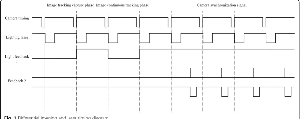
Figure1shows a schematic diagram of image differen-tial timing based on active laser detection. The timing sequence is distributed and controlled by the unified timing control hardware, so it can synchronize the time of each part. The timing scheme uses precise synchron-ous control to perform timing control on the lighting laser output/off time, camera integration time, and light output feedback. In order to ensure that the integral im-aging of the infrared camera will not be affected by the incidental effects such as laser scattering and thermal ef-fects, at the same time, strict timing control of the cam-era’s coarse tracking/fine tracking and illumination light can be achieved. Under the strict timing control con-ditions, the light irradiation of the dynamic target is performed in a staggered light-emitting manner, the image before and after the irradiation is subjected to background rejection, the target position can be rela-tively smoothly extracted. The medium-wave infrared camera has a frame frequency of 500 Hz. Therefore, even a fast-moving missile will not have much move-ment distance within 2 ms. In this case, it is effective to use differential method for image recognition and capture.
3 Method: design of image differential processing technology based on laser echo
3.1 Based on laser active detection cat eye image processing system function distance calculation
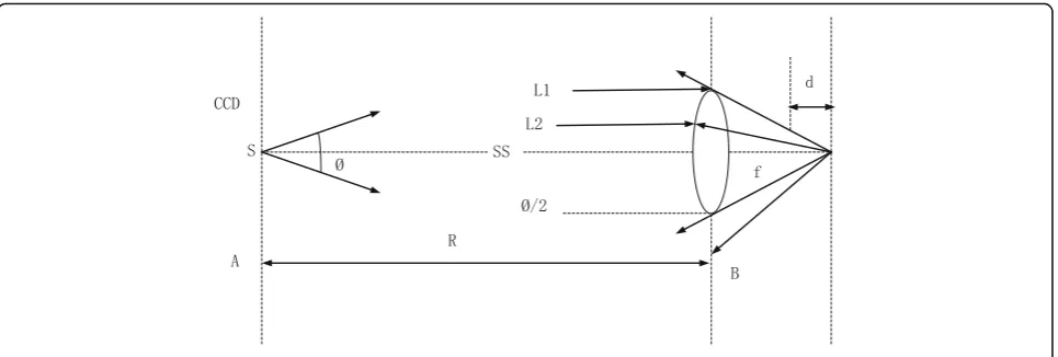
The image differential processing method based on active laser detection of cat eye image effect has a farther detec-tion distance than passive image processing. With the same target radiation, the image processing can achieve the capture of the target at a further distance. Based on the laser active detection image processing system, action distance diagram is shown in Fig.2.
Setting the cat’s eye target’s aperture to beDs, the focal
distance isfs, and the defocus amount is, use thed
geo-metric optics to derive the cat’s eye target effective aper-ture that contributes to the reflection section:
D0 ¼ fsDs=ðfsþ2dÞ ð1Þ
The effective area of the cat’s eye target:
As¼πD0=22¼πfs2Ds2= 4ðfsþ2dÞ
2
ð2Þ
In the case of normal incidence, the back beam spread angle (full angle) caused by the defocus amount calcu-lated by geometrical optics is
θs¼2tg−1 dDs=ðfsþdÞ
2
≈2dDs=fs
2 ð3Þ
In Fig.2, A is the medium-wave infrared detector and B is the cat eye target optical lens. The laser is emitted from S. The distance between the medium-wave infrared detector and the cat’s eye target is the R. The angleθtof
the emitted laser beam θsis the back beam angle of the
cat’s eye. According to the principle of geometric optics, the area of the laser light emitted from A to B is
Ss¼π½Rtgðθt=2Þ2≈πR2θ2t=4 ð4Þ
The area of the laser spot at the A reflected by the cat eye target lens at B is
Sr¼π Rþ
Ds=2
tgðθs=2Þ
tgθs 2
2
≈π RþDs θs
θs
2
2
¼π RdDs fs2 þ
Ds
2
( )
" #2 ð5Þ
The laser power Ptemitted by the launching system is
transmitted through the atmosphere and reflected by the cat’s eye and then transmitted through the atmosphere and received by the medium-wave infrared detector. The optical power analysis at each point is as follows:
The optical power received on the cat eye target lens at B is
PS1¼PtτtτAs=Ss ð6Þ
The optical power output on the cat eye target lens at B is
PS2¼PS1τ2SρS¼Ptτtττ2SρSAs=Ss ð7Þ
The echo optical power detected by the cat eye target detected by the medium-wave infrared detector at A is
PrS¼PS2ττrAr=Sr¼Ptτtτrτ2τ2SρSAsAr=ðSsSrÞ ð8Þ
PrSN ¼PrS=Nt; ð9Þ
where τt is the laser emissivity, τ is the laser single-pass
horizontal atmospheric transmissivity, τ2is the laser double-pass horizontal atmospheric transmissivity,τSis the
transmittance of the cat’s eye target optics lens, ρS is the
cat’s eye target target’s surface reflectivity, the transmittance
τr is the area of the optical system, Ar is the laser echo
power received by a single pixel,PrSNis the number of
im-aging pixels for the cat’s eye, andNtis generally taken as 9.
NEPis the noise equivalent power of the infrared cam-era, which can be calculated byD*.
NEP¼ðAΔfÞ1=2=D ð10Þ
SNR¼PrSN=NEP ð11Þ
Among them,Δf= 1/2 tint, tint is the integration time of the detector, tint is second;Ais the area of the single pixel.
SNR≥2.5(8dB) is normal circumstances, and stable tracking of goals can be achieved.
This paper takes the image capture capability of a 100-mm medium-wave infrared system as an example for simulation calculation. When the distance of the cat’s eye system is 6 km, the effect distance of the image de-tection system meets the requirement of the index is an-alyzed (Table1).
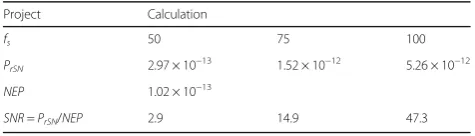
By simulating the conditions and substituting them into the above calculation formula, the working distance of the medium-wave infrared imaging system under this condition can be obtained. This calculation uses a back-calculation method, and the simulation results are shown in Table2.
Through calculation and simulation, it can be seen that when the cat’s eye imaging system focal length is 50~100 mm, the illumination laser power is 0.5 W, and the laser beam angle is 1 mrad, meeting the SNR 2.5 require-ments, the 6km laser echo image can be extracted and de-tected under this parameter condition. If the traditional detection method is used, the 6km target detection under this condition can not be realized.
3.2 Image differential capture processing system software and hardware design
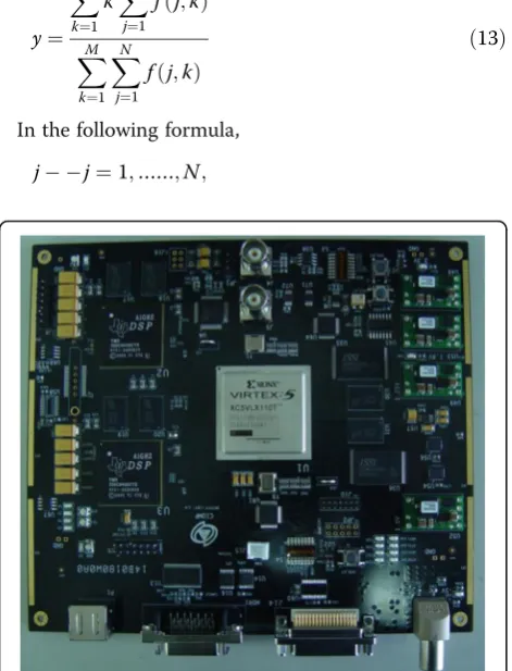
shape, image gray, and other related information are calculated to ensure the accuracy of the extracted target. Figure 3 is a block diagram of the image processing plat-form. The processing platform takes DSP as the core pro-cessing element. Figure 4 shows the hardware processing appearance of the system. The hardware adopts embedded design to ensure the independent operation of the system.
Interface designs:
□Two RS422 interfaces
□Two PAL standard analog video interfaces
□One CameraLink digital video input interface
□+ 5 V power connector
The image filtering process employs an adaptive me-dian filter approach.
The adaptive median filtering algorithm consists of two parts, called level A and level B. The algorithm is as follows:
Level A: A1 =Zmed−Zmin.
A2 =Zmed−Zmax.
If A1 > 0 and A2 < 0, go to level B. Otherwise, increase the size of filterSxy.
Repeat step A if the size of filterSxy<Smax.
Otherwise, use zxy as the output value.
Level B: B1 =Zxy−Zmin.
B2 =Zxy−Zmax.
If B1 > 0, and B2 < 0, useZxyas the output value.
Otherwise, useZmedas the output value.
This filtering method has the following three characteristics:
Removed salt and pepper (pulse) noise Smoothed other non-pulse noises
Reduces image distortion caused by ordinary median filtering, such as thin or thick edges on objects.
Image binarization uses an adaptive threshold method. For weak targets or images with strong noise interfer-ence, the target is almost submerged in the background noise. In this paper, two-dimensional maximum entropy adaptive threshold selection method is used to solve this problem. The two-dimensional maximum entropy threshold method uses a membership function param-eter to correlate with a threshold value. Through the optimization search, the maximum value of the fuzzy partition entropy is found to be the segmentation threshold. The one-dimensional maximum entropy method is based on the original histogram of the image. It uses only the pixel’s own gray information and does not consider the spatial distribution of the pixels. It is very sensitive to noise. The two-dimensional maximum entropy makes full use of the spatial relationship be-tween the image pixels themselves and the pixels, estab-lishes a two-dimensional histogram, calculates the maximum entropy defined therein, and selects the opti-mal threshold based on this. The introduction of spatial relationships improves the noise immunity of the algo-rithm. In this paper, morphological filtering is used to remove the noise contained in the binarized image, and morphological filtering includes erosion and swelling. Corrosion is the process of eliminating boundary points and shrinking the boundaries to the interior. Swelling is the process of merging all the background points in con-tact with an object into the object and expanding the boundary to the outside.
3.3 Target capture tracking algorithm
The centroid tracking method is based on image feature self-adaptive selection of image thresholds, image binariza-tion processing according to image thresholds, and calcula-tion of target centroids on binarized images, using the gray distribution centroid of the target image as a tracking point. According to the definition, in anN×Nwindow, the gray centroid location is obtained from the following formula:
x¼
XM
j¼1
jX
N
k¼1
f jð;kÞ
XM
k¼1 XN
j¼1
f jð;kÞ
ð12Þ
Table 2Detection results of medium-wave image processing system
Project Calculation
fs 50 75 100
PrSN 2.97 × 10−
13 1.52 × 10⁻¹² 5.26 × 10⁻¹²
NEP 1.02 × 10⁻¹³
SNR=PrSN/NEP 2.9 14.9 47.3
Table 1Image capture capability parameter table
Project Parameter Unit Value
Laser parameters θt Launch mrad 1
Pt Laser W 0.5
τt Laser 0.57
Cat eye target parameters Ds Cat mm 50
fs Cat mm 50~100
d Cat mm 0.25
τS Cat 0.7
ρS Cat 0.15
Infrared detection image system parameters
D Optical mm 100
f focal mm 300
τr Optical 0.55
Tint Integration ms 3
D∗ Infrared cm.w−1
.Hz1/2
1.9 × 10¹¹
S Pixel μm 15
Nt Point 9
y¼
XN
k¼1
kX
M
j¼1
f jð;kÞ
XM
k¼1 XN
j¼1
f jð;kÞ
ð13Þ
In the following formula,
j j¼1;……;N;
k k¼1;……;N;and
N NNwindow;
f(j,k)——pixel gray value of image at (j,k) point. Since the process of calculating the centroid is a statis-tical average process, the tracking point calculated by it is not the individual brightest point position, but the gray-weighted average position of each pixel in the image. Therefore, taking the centroid as the tracking point, the tracking random error is small.
The target enters the field of view. Within a short period of time (such as three frames of images), various static characteristics (such as gray scale, and shape) should not undergo large abrupt changes. Motion char-acteristics (such as motion trajectory) should follow certain rules. We use this premise to capture the target. Due to the characteristics of the image sensor itself and the influence of ambient noise, the candidate regions in the image obtained from the previous preprocessing may be targets, and some may only be some noise interference. The moving target has obvious static and motion characteristics. Noise interference is generally random, and its static characteristics and motion char-acteristics are generally not regular. In this paper, based on the grayscale features of the image, the target is cap-tured frame by frame. If the target is capcap-tured, the miss distance of three consecutive image objects is linearly judged. According to the field experience, the motion Fig. 3Image processing platform block diagram
trajectory within three frames of the moving object should be approximately linear. Change, such as a lin-ear change, determines that it is the true goal and moves into the tracking process. There are many iso-lated regions in the binarized image. In order to extract the target features, it is necessary to mark the region. In this paper, an eight-neighborhood labeling algorithm is used. In this paper, the area and circle shape parame-ters are selected as the true target discrimination condi-tions to remove the influence of false targets. The area parameters can remove much smaller and smaller false targets; the circular shape parameters can distinguish whether the target is a round target.
Area (S): For the binary image of the regionR(N×M), the area of the region R is represented by scanning the image and calculating the total number of pixels that meet the conditions.
Circular shape parameters: Circularity and eccentricity are used as discriminating conditions for circular targets.
Circularity:C=L2/SL––perimeter;S-area
Eccentricity: E= |a-b|a-X-direction length of region;
b-Y-direction length of region
3.4 Capture targeting accuracy design based on cat eye image effect
Using the passive detection method in the past, be-cause the target temperature characteristics of the tail flame are very strong, it will interfere with the image processing system, making it unable to effectively cap-ture the optical window of the target photoelectric device, and it cannot guarantee that the laser irradi-ation point always acts on the optical window of the target photoelectric device. In this paper, the wave in-frared laser is used as the illumination laser. Through the “cat eye” effect of the seeker, the “cat eye” effect is used to achieve the high-precision tracking and tar-geting of incoming missile seekers using the original return characteristics and collimation characteristics. At the same time, the optical design of laser emission and infrared tracking common aperture is used to
achieve no-angle difference and no-difference point tracking emission.
Based on the above discussion, according to the tual work of the photoelectric detection system, the ac-curacy of the main and passive detection tracking and sighting is shown in Fig.5.
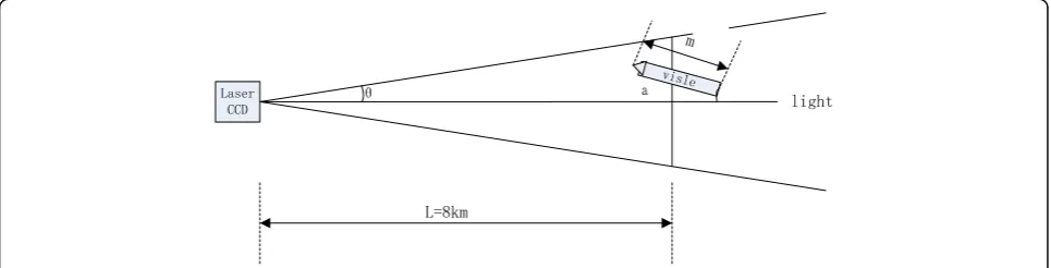
Because the missile’s flight direction and its use of in-frared guidance mainly track the strong parts of the en-gine’s tail flame and other heat radiation, the missile’s flight direction will have a certain angle with the optical axis of the onboard optoelectronic countermeasure equipment’s optical system (α). Using the traditional in-frared passive tracking method, the image processing system will automatically capture the incoming missile tail flame. According to the angle of the optical axis of the optical system of the missile and airborne optoelec-tronic countermeasure equipment, the angle of the laser beam θ, the tracking accuracy βof the servo sys-tem, the distance L between the missile and the coun-termeasure equipment and the lengthmof the missile, the interference probability of the system can be calcu-lated as:
Fðα;β;θ;L;mÞ ¼ 1 βpffiffiffiffiffiffi2π
Z Ltanθ−msinα
−Ltanθ−msinα
exp − x
2
2β2
ð14Þ
According to the formula, when the laser beam diver-gence is 200 urad, the tracking accuracy is 50 urad, the missile is 4 km from the airborne optoelectronic coun-termeasure equipment, and the angle between the mis-sile body and the optical axis is 8.04°, the probability of the laser irradiating the warhead optical window is ap-proximately 50%. Due to the rapidity and strong maneu-verability of missiles, and the flipping action of aircraft when evading missiles, the angle between the missile and the optical axis of the laser is greater, and the prob-ability of success of interference is also lower.
When the laser active detection technology is used to track the incoming missile optical equipment
under the same conditions, due to the cat eye image effect, the image processing system can effectively capture the missile optical window, and the probabil-ity of the laser striking the warhead optical window is about 95.44%.
When using passive detection methods, to increase the probability of the laser irradiating the optical window of the warhead, it is necessary to increase the beam spread angle and the light output power of the interfering laser.
At the same time, the volume and weight of the laser will increase exponentially, which is not conducive to system integration. With the active laser detection method, using the cat eye image effect, a reasonable optical path design, and targeted image processing and servo control algo-rithms, can achieve high-precision, high-efficiency inter-ference, and damage to incoming targets.
The echo image of the cat’s eye is approximate Gaussian and has the following properties:
Rþ∞ −∞
Rþ∞
−∞ j f2ðj;KÞ Rþ∞
−∞ Rþ∞
−∞ f2ðj;KÞ
¼x0 Rþ∞
−∞ Rþ∞
−∞ k f2ðj;KÞ Rþ∞
−∞ Rþ∞
−∞ f2ðj;KÞ
¼y0
ð15Þ
When the above formula is applied to a digitized image, the grayscale center position of the target image point can also be calculated. This is the weighted gravity method. The formula is as follows:
x¼α
XM
j¼1
jX
N
k¼1
f2ðj;kÞ
XM
k¼1 XN
j¼1
f2ðj;kÞ
;y¼α
XM
j¼1
kX
N
k¼1
f2ðj;kÞ
XM
k¼1 XN
j¼1
f2ðj;kÞ
ð16Þ
In the following formula,
j j¼1;……;Mand
k k¼1;……;N;
f(j,k)——pixel gray value of image at (j,k) point
α——subdivision multiples.
The absolute value of the weighted barycentric method weight is increased ∣f(j,k)∣ compared to the classical barycentric algorithm. This makes the weighted barycen-tric method utilize the high-SNR target image center
Fig. 11Main system tracking error simulation curve
information more than the classical barycentric method and enhances the anti-noise interference ability and sub-division of the algorithm.
According to the actual effect test, by properly selecting the calculation window, the 3 × 3 target centroid accuracy is better than 0.25 pixels. Compared with the classical gravity center algorithm, the weighted centroid method is simple, practical, and has strong anti-interference ability.
3.5 Analysis of tracking accuracy under cat eye image effect The cat eye echo image based on laser active detection has the features of sharp edges and obvious targets. Compared with the traditional passive image processing, this method can effectively improve the tracking accuracy of the system and maximize the use of active imaging data mining. The analysis target is the horizontal flight of the rattlesnakes AMI-9X head-on, assuming that the target motion is converted to a turntable speed of 5°/s and an ac-celeration of 1°/s2. Equivalent sineθ= 25 sin(0.2t) is used as a simulation input to evaluate the tracking accuracy of the system. The optical image sensor has time lag and the system bandwidth is limited. It will have a certain impact on the tracking accuracy and the transition process and must be fully considered in the system tracking accuracy and stability. In the main system speed loop design, speed loop correction function is
GV ¼
1570 0ð :4Sþ1Þð0:0061Sþ1Þ 7:5Sþ1
ð Þð0:0039Sþ1Þ ð17Þ
Speed loop open-loop Bode diagram as shown in Fig.6. Open-loop shear frequencyωcv= 86.2 rad/s.
Main system position loop design.
Gp ¼
112 0ð :45Sþ1Þð0:83Sþ1Þ 2:5Sþ1
ð Þð2:1Sþ1Þ ð18Þ
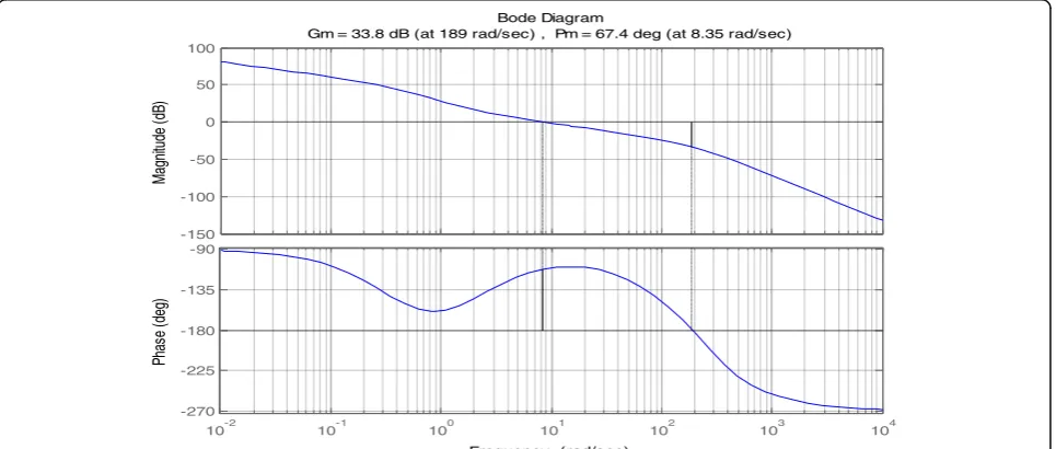
The position loop open-loop Bode diagram is shown as in Fig.7. Open-loop shear frequencyωcv= 8.35rad/s.
Subsystem speed loop design.
GV ¼
1000 0ð :09Sþ1Þð0:000151Sþ1Þ 10:5Sþ1
ð Þð0:00039Sþ1Þ ð19Þ
The subsystem speed loop open-loop Bode diagram is shown in Fig.8.
Subsystem location loop design
Gp ¼
300 0ð :85Sþ1Þð1:8Sþ1Þ 2:5Sþ1
ð Þð2:1Sþ1Þ ð20Þ
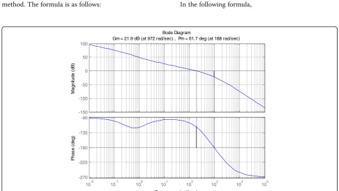
The open-loop Bode diagram of the subsystem pos-ition loop is shown in Fig.9.
The open-loop shear frequency is 188 rad/s. Control system simulation structure shown in Fig.10.
The system stability tracking main system tracking error simulation curve is shown in Fig.11.
curve is shown in Fig.12.
In summary, the tracking accuracy of the main system of the image processing system can reach 0.2 mrad, the divergence angle of the illumination laser is equal to or greater than 1 mrad, and the 1/3 spot diameter require-ment can be satisfied and the active illumination laser can cover the target. Subsystem tracking accuracy can reach 47 urad, fully utilizing the advantages of laser ac-tive illumination image differential system and greatly improving the system’s tracking accuracy.
4 Differential image processing results and discussions
4.1 Complex background image differential processing algorithm
After the high-repetition laser emission, the infrared image of the effect of the cat’s eye image is accurately
master and passive image difference strategies to obtain images under complex background conditions can greatly increase the target’s capture probability. Figure 13shows the timing of image acquisition and illumination lasers under the combination of main and passive detection. Figure14is an example of image difference processing.
4.2 Image single-frame weak target processing algorithm After observing and analyzing the image, we found that the target in the image is not the highest in the entire image, but there is still a certain difference from the local back-ground in the small area where it is located. The pixels in the higher gray background, although the gray value is rela-tively large, have a slow transition with the surrounding background in its local area. Based on this gray feature of the target and the background, the system uses local back-ground prediction. The method is to use a 7 × 7 filter tem-plate to convolve the source image, perform the difference calculation between the source image and the convolution image, and perform image target processing on the differ-ence image. The specific form of the template is as follows:
Y m;ð nÞ ¼ 1 64
2 2 2 2 2 2 2 2 1 1 1 1 1 2 2 1 0 0 0 1 2 2 1 0 0 0 1 2 2 1 0 0 0 1 2 2 1 1 1 1 1 2 2 2 2 2 2 2 2
2 6 6 6 6 6 6 6 6 4
3 7 7 7 7 7 7 7 7 5
ð21Þ
In the image target tracking process, the wave gate tracking method is adopted, that is, the target wave gate image is extracted at the corresponding position of the image, and only the target in the wave gate is calculated and processed to extract the miss distance. This method can effectively remove the impact of the wave outside the interference target. Improve the stability and rapidity of target tracking. When the target gray level changes greatly, the target will lose instantan-eously. Therefore, trajectory prediction on the target is an indispensable part of the tracking process. Trajectory prediction means that when a target in a wave gate is lost, the position of the next target should be predicted based on the information on the positions, speeds, and directions of the previous frames, so as to drive the servo system to follow the target according to the predicted value. A stable tracking of the target occurs.
In this paper, the least squares method is used to fit the real space of the target, so as to calculate the pre-dicted position of the next frame.
The following formula synthesizes the miss distance and the encoder value into the true spatial position of the target:
ΔA¼ arctan xf cos E
0
ð Þ−ysinð ÞE0
A¼A0þΔA
E¼ arctan ðf sinð Þ þEo ycosð ÞE0Þcosð ÞΔA.
f cosð ÞE0−ysinð ÞE0
ð22Þ
f——focal length, mm
A0——encoder bearing value, vad E0——encoder pitch value, vad
x——image sensor target pixel size, mm
Taking into account the actual target in the short-time flight process, the target flight path will not have large sudden changes. This article uses the parabolic least square method formula to predict the target spatial pos-ition, which can effectively improve the robustness of the system and make the target lost. For a certain period of time, the device can still follow the correct trajectory to ensure that the system can still track the target cor-rectly when the target reappears.
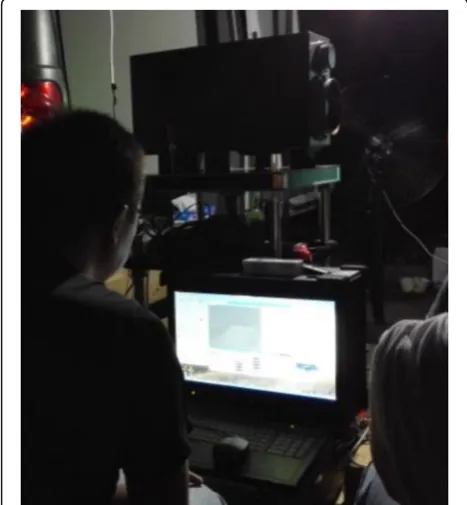
4.3 Image differential capture test
In order to verify the effectiveness of the high-dynamic and low-gray target image differential capture technology Fig. 17Effect of a long-range weak target imaging experiment with laser active illumination.a1 km no cat’s eye echo background image and (b) 1 km cat’s eye echo image
system. At the same time, if the target cannot be effect-ively identified under the condition of traditional passive imaging, this technology can achieve rapid capture of the target and achieve the purpose of rapid alarm tracking of the optical imaging system. According to the test analysis, when the cat’s eye echo is strongest, the defocusing amount of the seeker is 0. When the defocusing amount of the seeker is greater than 1 mm, the echo intensity de-creases about 30%. Figure 15 shows the cat eye effect image recognition field test site. Functional tests of cat's eye echo detection were carried out at different distances, laser power and laser divergence angles. Figure16shows the seeker simulator used in the test. The simulator uses a medium wave infrared detector. The main indicators of the simulator are basically consistent with the actual mis-sile seeker. Figure17shows the laser echo image of the 1 km experiment. The purpose of the experiment is to verify the effect of cat eye effect produced by laser echo at a dis-tance. From the experimental results, the cat eye effect under laser and no laser conditions is very obvious. Differ-ential illumination can be implemented in this way to achieve fast acquisition of image targets in complex back-ground. Figure 18 shows the intensity of the cat's echo image using different laser divergence angles in the 1km test. Figure 18a is a laser echo image with divergence angle 5mrad, and 18b is the laser echo image at diver-gence angle 1mrad. From the comparison of the two im-ages, it can be found that the higher the laser divergence angle is, the greater the echo intensity is. We can see that the relationship between the laser echo intensity and the divergence angle is approximately squared.
5 Conclusions
This paper proposes a high-dynamic low-gray target image differential capture technology based on active laser detection, which achieves the function of the traditional passive optical imaging system unable to capture the tar-get by the tartar-get gray difference value under complex background conditions. This method based on cat eye echo image processing can achieve accurate positioning of the target seeker. The image has many advantages such as clear edges, high-contrast, long-range, and strong
1. Author 1: Zhaobing Chen received the BS degree in Qingdao University, Qingdao, China, in 2005, the Ph. D degree in Mechanics from Changchun Institute of Optics, Fine Mechanics and Physics, Chinese Academy of Science, Changchun, China, in 2011. In 2008, he joined Changchun Institute of Optics, Fine Mechanics and Physics, Changchun, China. Before 2013, he was an assistant professor in Changchun Institute of Optics, Fine Mechanics and Physics. From 2013 to now, he is an associate professor of Changchun Institute of Optics, Fine Mechanics and Physics. His research interests include research on optical mechatronics, image processing, and laser echo technology research. 2. Author 2: Kui Shi from 2014 to now, he is an associate professor of
Changchun Institute of Optics, Fine Mechanics and Physics. His research interests include research on optical mechatronics, image processing, and laser echo technology research.
3. Author 3: Ning Chen from 2012 to now, he is an associate professor of Changchun Institute of Optics, Fine Mechanics and Physics. His research interests include research on optical mechatronics, image processing, and laser echo technology research.
4. Author 4: Guannan Li from 2014 to now, he is an assistant professor of Changchun Institute of Optics, Fine Mechanics and Physics. His research interests include research on optical mechatronics, image processing, laser echo technology research, and laser vision measurement. 5. Author 5: Xingyang Liu from 2016 to now, he is an assistant professor of
Changchun Institute of Optics, Fine Mechanics and Physics. His research interests include research on optical mechatronics, image processing, laser echo technology research, structure design of precision machinery, and optical system.
Ethics approval and consent to participate
Approved.
Consent for publication
Approved.
Competing interests
The authors declare that they have no competing interests. And all authors have seen the manuscript and approved for submission. We confirm that the content of the manuscript has not been published or submitted for publication elsewhere.
Publisher’s Note
Springer Nature remains neutral with regard to jurisdictional claims in published maps and institutional affiliations.
Received: 10 June 2018 Accepted: 10 August 2018
References
1. Zhaobing C, Kui S, Ning C,et al, The mechanical biosensor design and simulation based on micro mechanical cabity array structure [J]. Basic & Clinical Pharmacology & Toxicology. Vol.117, Suppl(4), 27, (2015) 2. Zhaobing C, Jin G, Bing W, et al, The structure design of complex nesting
3. Zhaobing C, The transmession scheme design about a medical laser optical fiber [J]. Basic & Clinical Pharmacology & Toxicology. Vol.118, Suppl(1),27, (2016)
4. Zhaobing C, Guannan L, Xingyang L, et al, The structure form layout and installation design about carbased photonics mast [J]. Journal of Discrete Mathematical Sciences & Cryptography.201, 231-238 (2017)
5. C. POLLAK, T. STUBINGS, H. HUTTER, Differential image distortion correction. [J]. Microsc. Microanal.7(4), 335–340 (2002)
6. X. Song, J. Chen, C. He, et al., A robust moving objects detection based on improved Gaussian mixture model. [J]. Int Conf Artif Intell Comput Intell
2(6), 54–58 (2010)
7. Gorur P, Amrutur B. Speed up Gaussian mixture model algorithm for background subtraction [C]. IEEE International Conference on Advanced Video and Signal-based Surveillance. 2011:386–391
8. V.T. Wang, P.M. Hayes, Synthetic aperture sonar track registration using SIFT image correspondences [C]. IEEE J. Ocean. Eng.42(4), 901–913 (2017) 9. S. Harput, J. Mc Laughlan, M. J. David Cowell, et al. New performance
metrics for ultrasound pulse compression systems. 2014 IEEE International Ultrasonics Symposium [C]. IEEE Conference Publications, 2014: 440–443 10. E.P. Haris, Consensus in networks of agents with unknown high-frequency
gain signs and switching topology [C]. IEEE Trans. Autom. Control62(8), 3993–3998 (2017)
11. G.L. Chen, S.H. Tsai, K.J. Yang, On performance of sparse fast Fourier transform and enhancement algorithm [C]. IEEE Trans. Signal Process.
65(21), 5716–5729 (2017)
12. R. M. Abidur, Rafat-Al-Islam. Fast normalized cross-correlation based retinal recognition. IEEE. 2014 17th International Conference on Computer and Information Technology (ICCIT) [C]. IEEE Conference Publications, 2014: 358–361 13. W. Sun, W.J. Niessen, S. Klein, Randomly perturbed B-splines for nonrigid image
registration [C]. IEEE Trans. Pattern Anal. Mach. Intell.39(7), 1401–1413 (2017) 14. E. Maguid, I. Yulevich, Multifunctional interleaved geometric-phase dielectric
metasurfaces. Sci Applvolume6, 17027 (2017)
15. S. Psilodimitrakopoulos, L. Mouchliadis, I. Paradisanos, Ultrahigh-resolution nonlinear optical imaging of the armchair orientation in 2D transition metal dichalcogenides. [J]. Sci. Appl.volume2, 16207 (2018)
16. Z. Zhang, H.J. Wang, Red light at intensities above 10 lx alters sleep––wake behavior in mice. [J]. Sci. Appl.volume5, 19025 (2017)